1 Nuevo proyecto
Abra IDEA StatiCa y seleccione la aplicación Member .
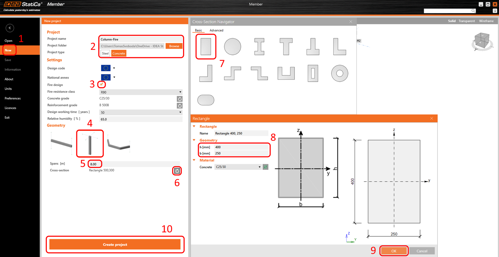
Cree un nuevo proyecto (1), escriba su nombre y seleccione la carpeta donde se guardará. A continuación, elija el tipo de proyecto Hormigón (2), active el Diseño contra incendio (3) y el tipo de Topología (4). Defina la altura de la columna como 8 m (5). Haga clic en Flecha (6) para definir la sección transversal. Seleccione la sección transversal rectangular (7). Modifique las dimensiones (8) y haga clic en el botón Aceptar (9). Por último, haga clic en Crear proyecto (10).
2 Diseño
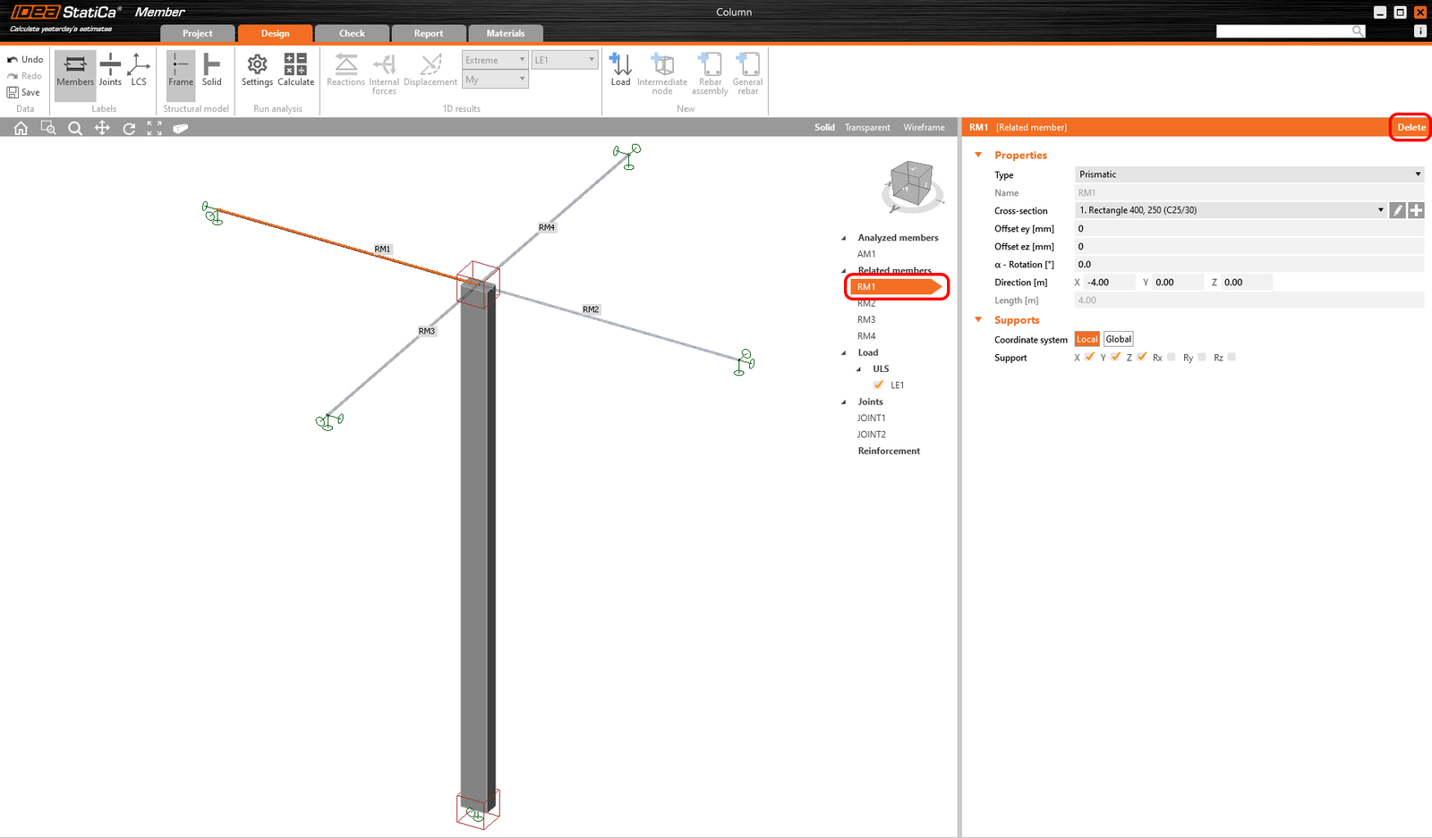
La columna se ha creado con los elementos relacionados. Elimine todos los Elementos relacionados.
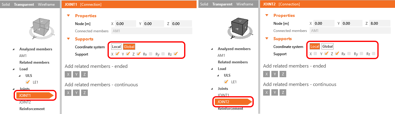
Establezca las condiciones de contorno según la figura adjunta. Ha creado las condiciones de contorno que representan la columna simplemente apoyada.
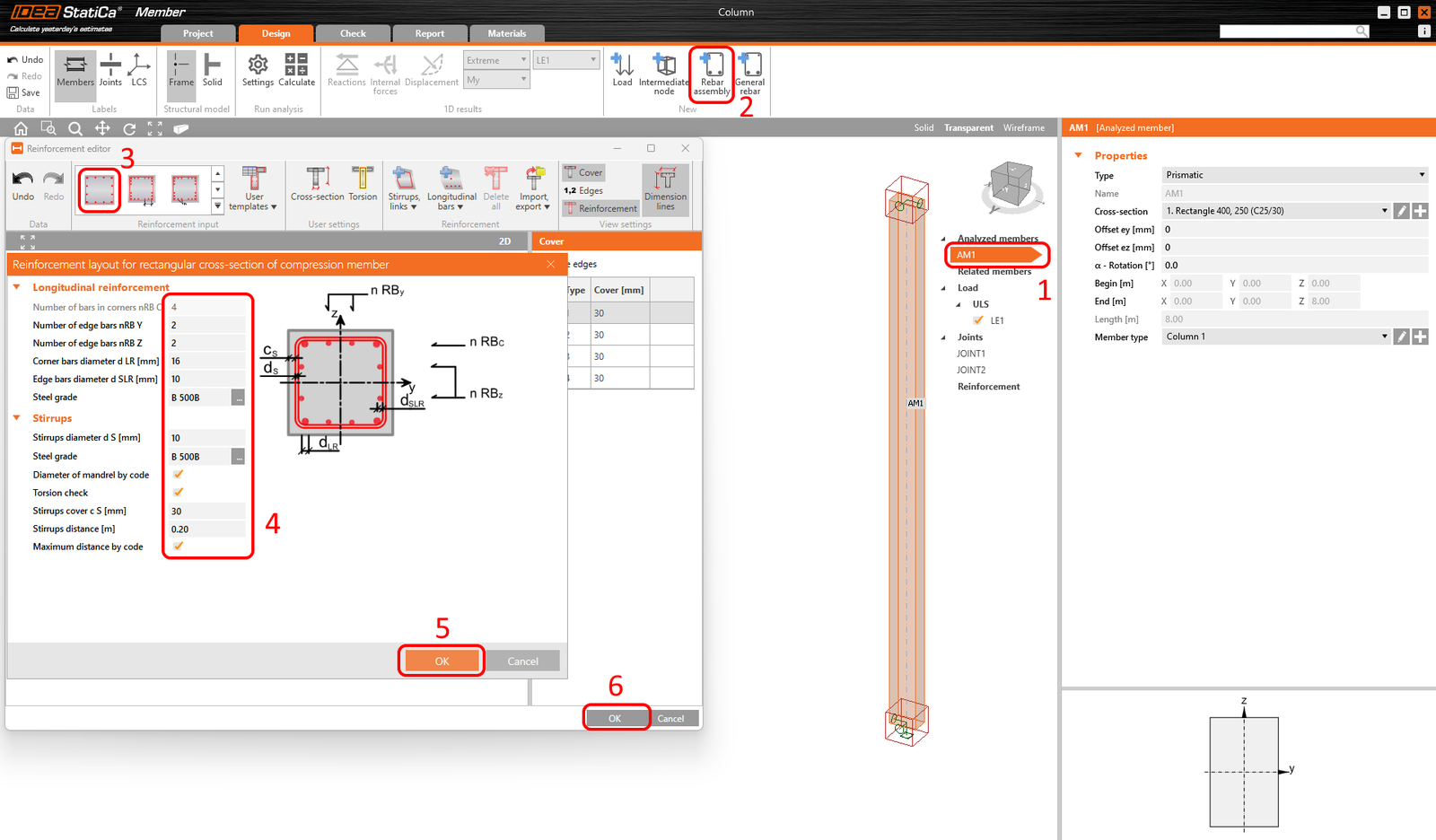
El siguiente paso es definir la disposición de la armadura. Seleccione el elemento analizado AM1 (1) y haga clic en el botón Conjunto de barras (2). A continuación, introduzca la armadura (3) utilizando la plantilla. Los valores están definidos, compruébelos (4) y confirme con Aceptar (5,6).
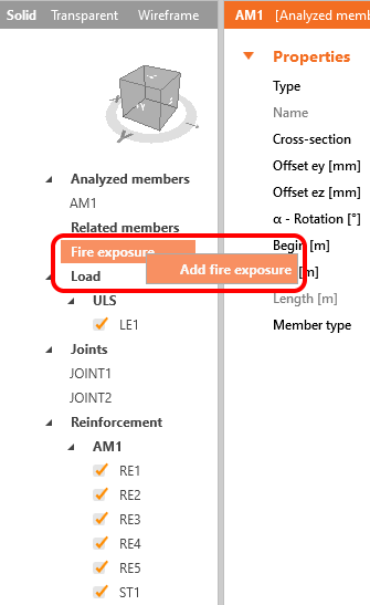
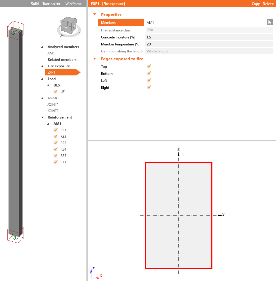
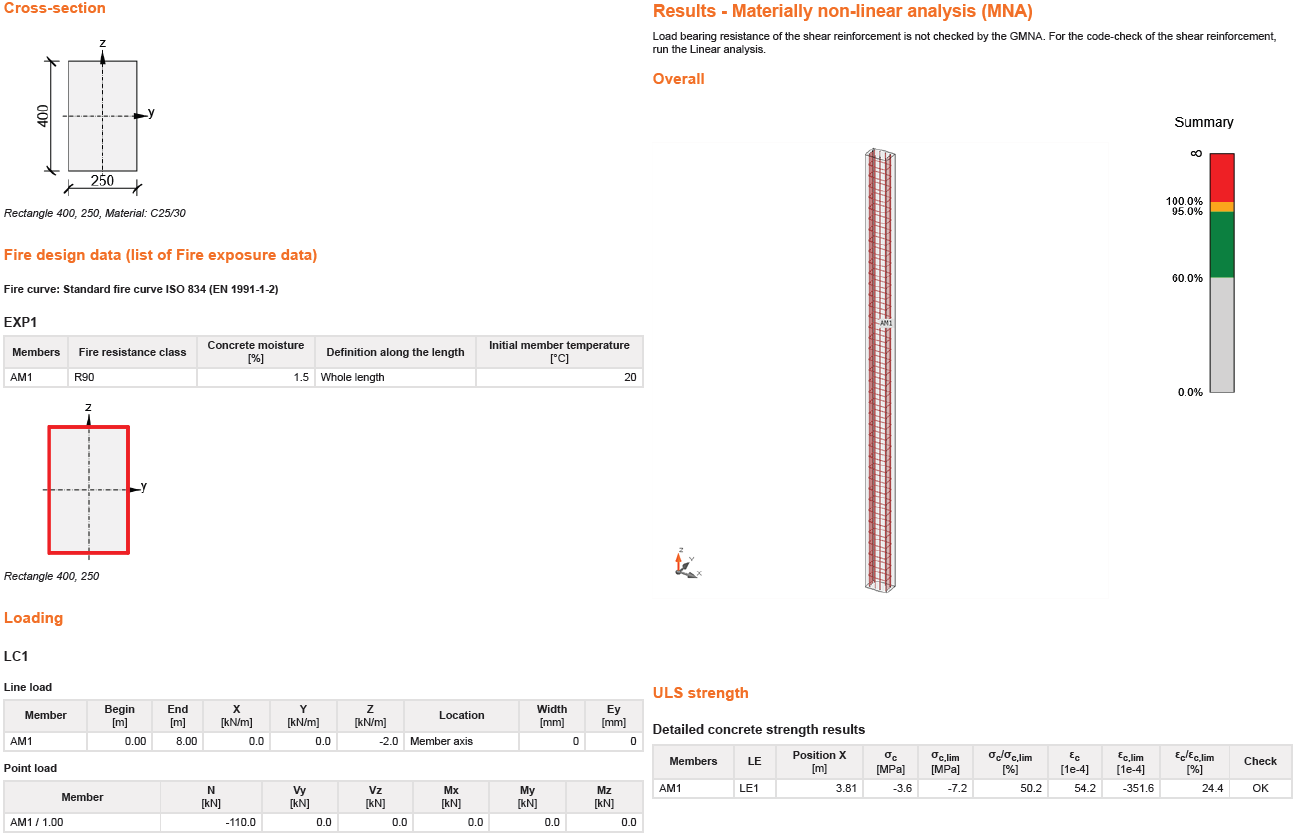
Los datos de exposición al fuego sirven para añadir las condiciones iniciales del análisis térmico. Comience haciendo clic con el botón derecho del ratón sobre Exposición al fuego-->Añadir exposición al fuego.
Haga clic en el botón Cursor en las Propiedades de exposición al fuego. Esto le permitirá iniciar la selección. Seleccione toda la columna y no olvide confirmar la selección.
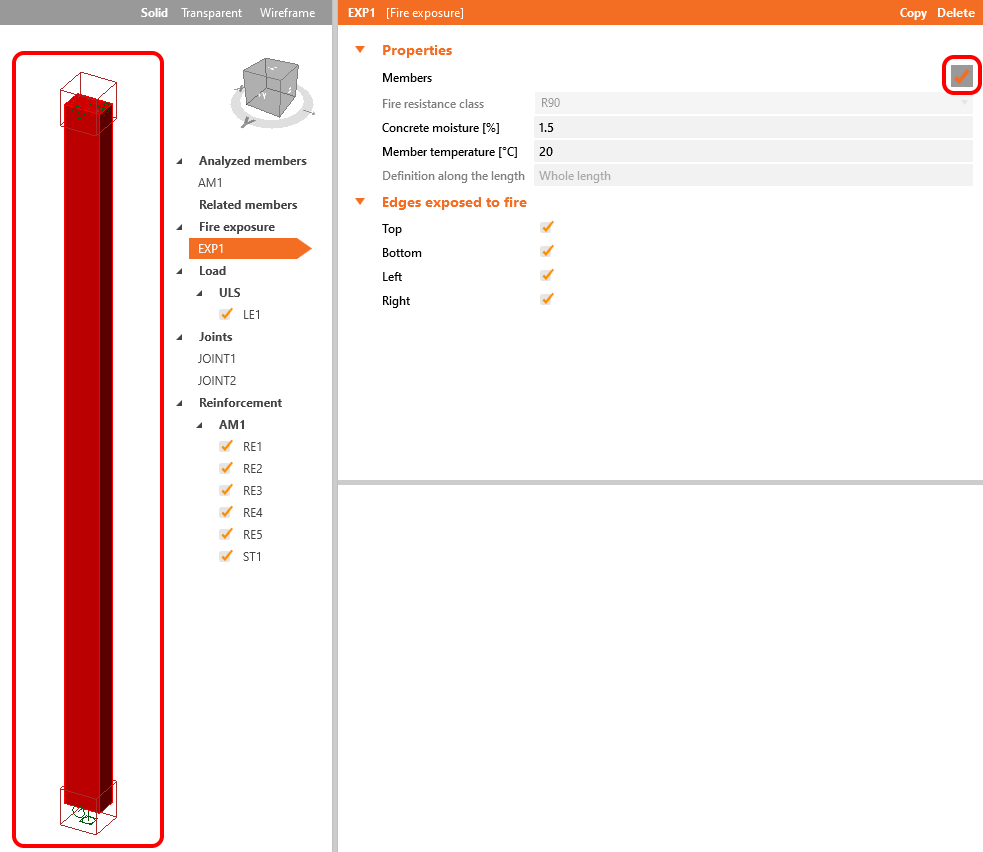
Las líneas rojas alrededor del rectángulo indican los bordes expuestos al fuego. Considere que todos los bordes estarán sometidos a la carga de fuego. Deje todas las casillas activadas.
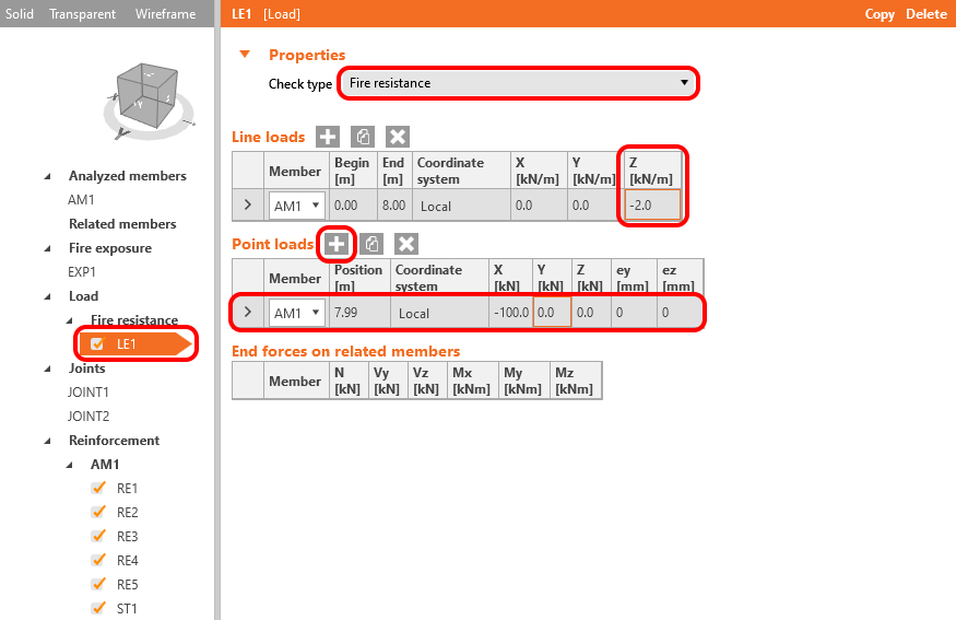
La carga utilizada para el diseño contra incendio, según EN 1992-1, puede considerarse como el 70% del ELU. La carga puntual y lineal representan la carga de diseño contra incendio.
3 Verificación
El modelo está listo. Puede comprobar las tablas de Degradación de materiales seleccionando Diseño contra incendio--> Degradación de materiales-->Hormigón o Armadura.
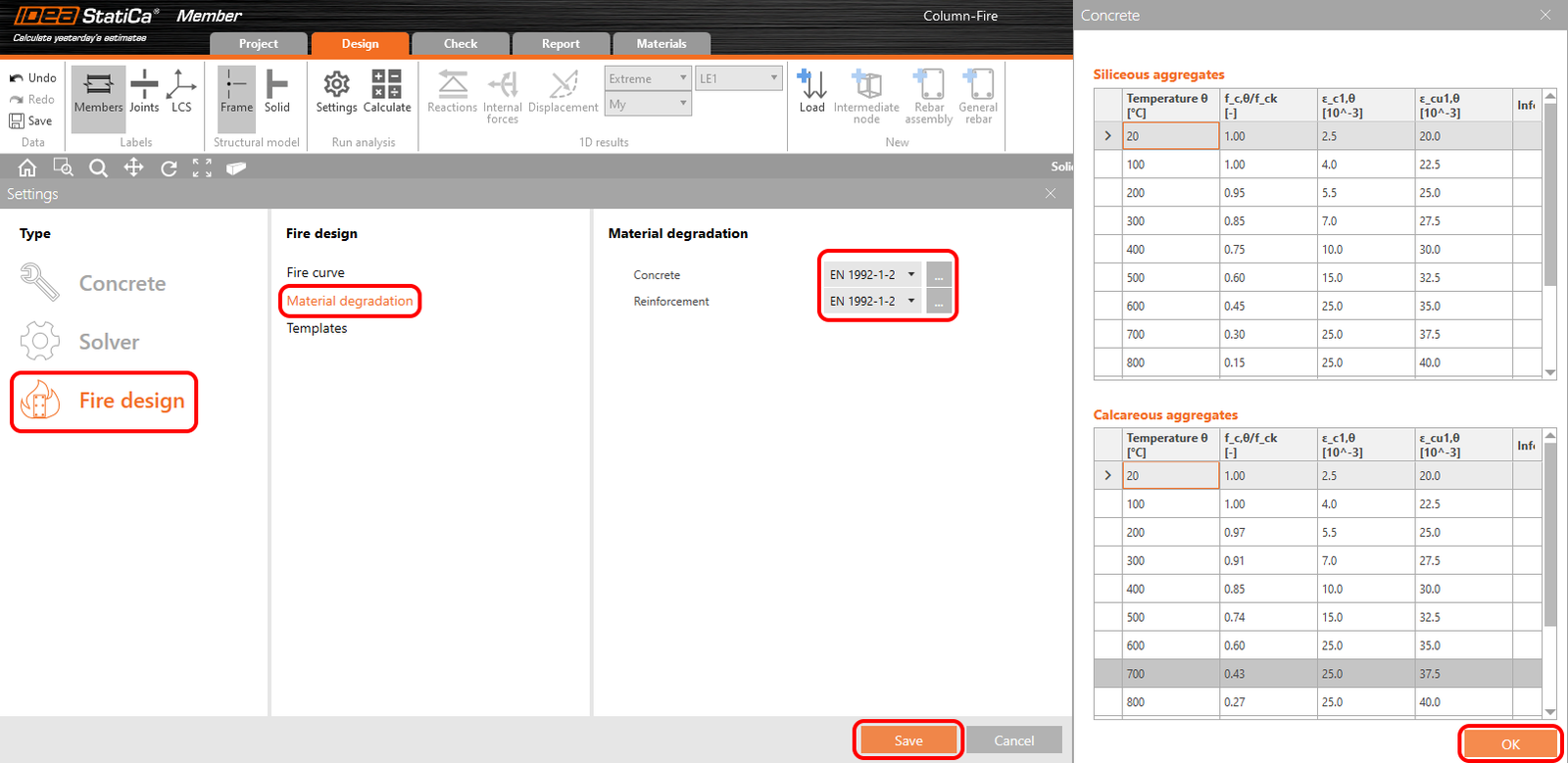
Deje las tablas tal como están, haga clic en Aceptar y Guarde la configuración.
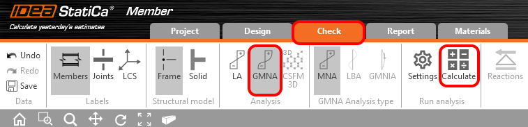
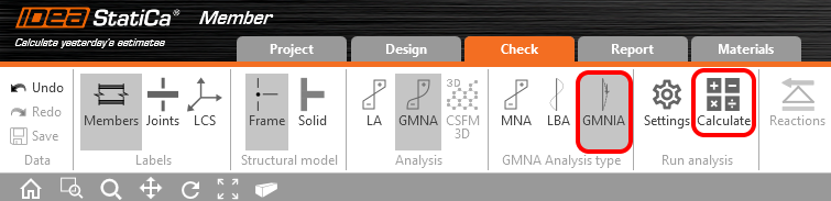
Vaya a la pestaña Verificación-->GMNA-->Calcular. Este procedimiento inicia el MNA - Análisis no lineal material.
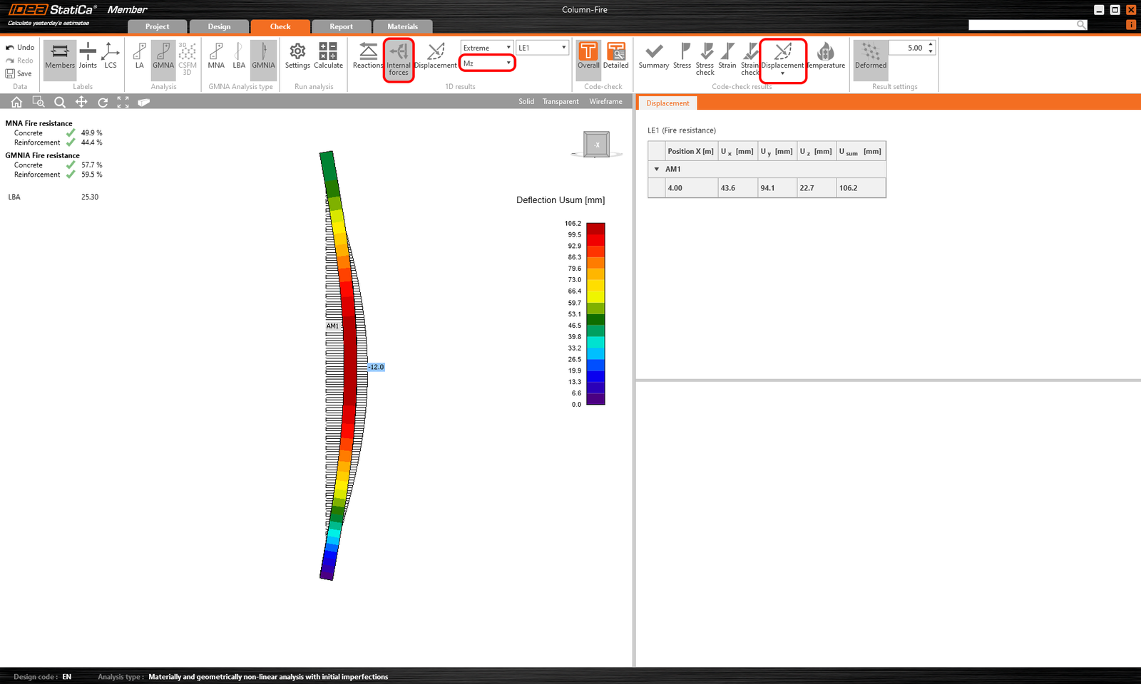
Una vez completado el cálculo, puede comprobar los resultados. Para ello, haga clic en Detallado y Temperatura. A continuación, debe elegir la sección crítica. También puede comprobar los esfuerzos internos. Haga clic en el botón Esfuerzos internos.
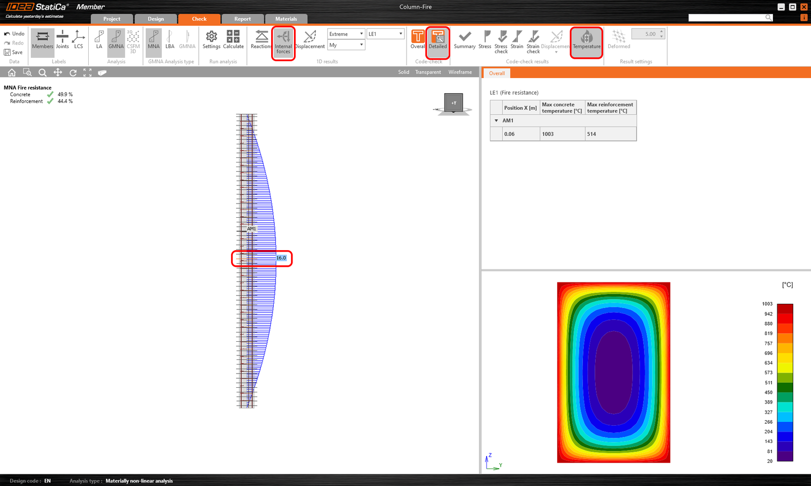
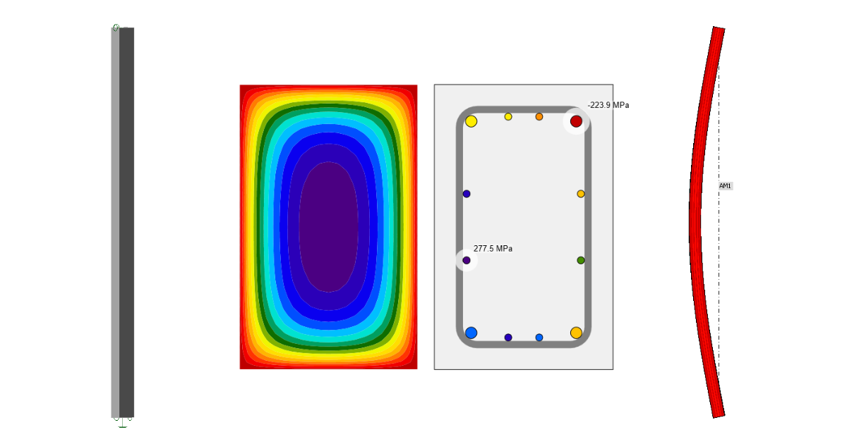
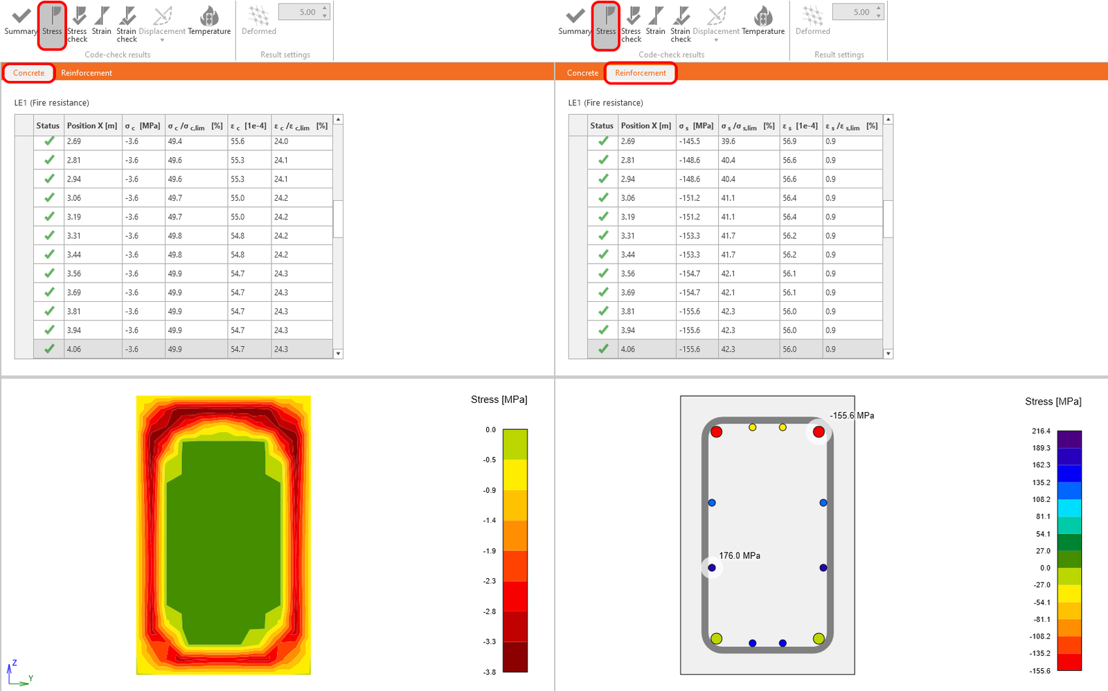
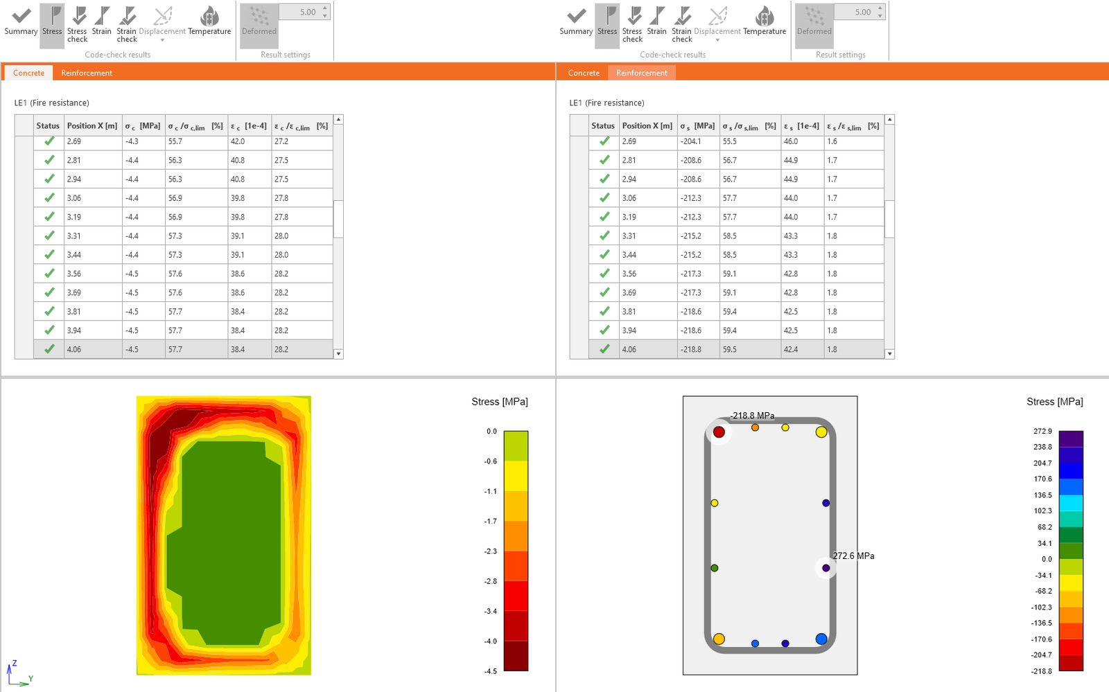
También puede comprobar la Tensión en el Hormigón o la Armadura.
Ejecute el LBA - Análisis lineal de pandeo.
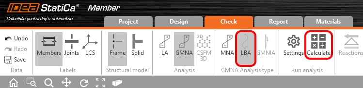
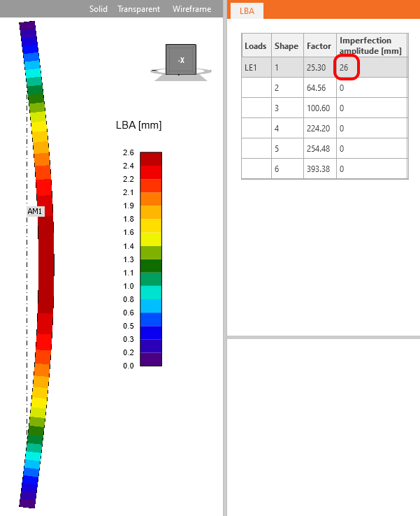
Cuando el cálculo esté completado, establezca la Amplitud de imperfección. El valor de la amplitud se calcula según EN 1992-1-1 artículo 5.2 (9).
Lea el siguiente artículo para aprender cómo definirla, incluyendo la amplitud adicional debida a la fluencia.
La amplitud incluyendo el efecto de la fluencia es 26 mm.
Inicie el GMNIA - Análisis no lineal geométrico y material con imperfecciones.
Este fue el último tipo de análisis. Puede comprobar los resultados de la misma forma que en el MNA. Debido al efecto de segundo orden, se pueden observar momentos flectores y deformaciones incrementados.
Puede comprobar y comparar las tensiones en el hormigón y en la armadura. No olvide hacer clic en Detallado y seleccionar la sección transversal crítica.
3 Informe
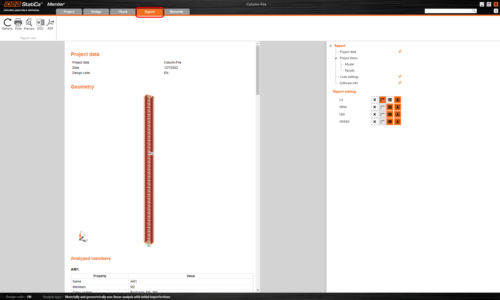
Vaya a la pestaña de informe. Aquí se puede imprimir el informe.
- Concrete
- Reinforced concrete
- Prestressed concrete
- Tutorials
Viga pretensada con aberturas (EN)
Leer más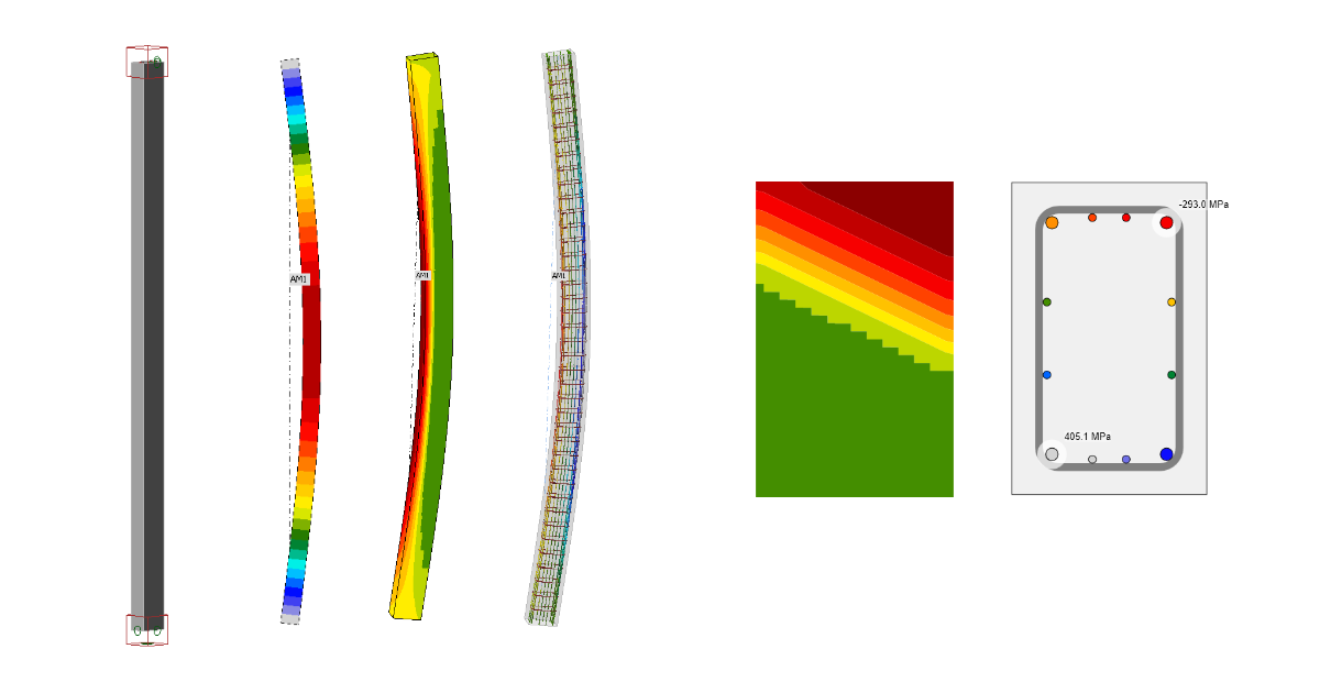
- Concrete
- Reinforced concrete
- Tutorials
Columna esbelta de hormigón (EN)
Leer más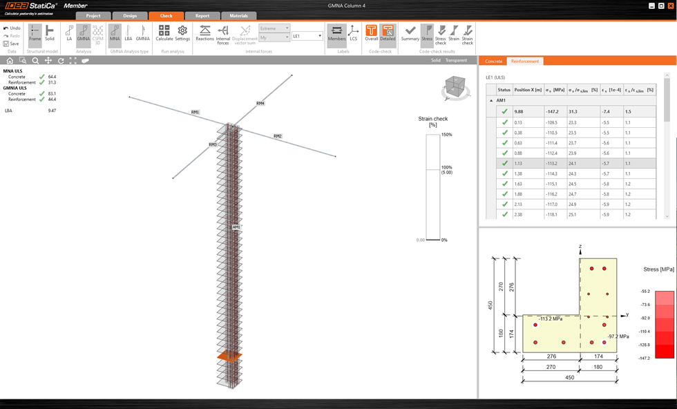
- Concrete
- Reinforced concrete
- Prestressed concrete
- Knowledge base
Diseño y verificación de columnas esbeltas
Leer más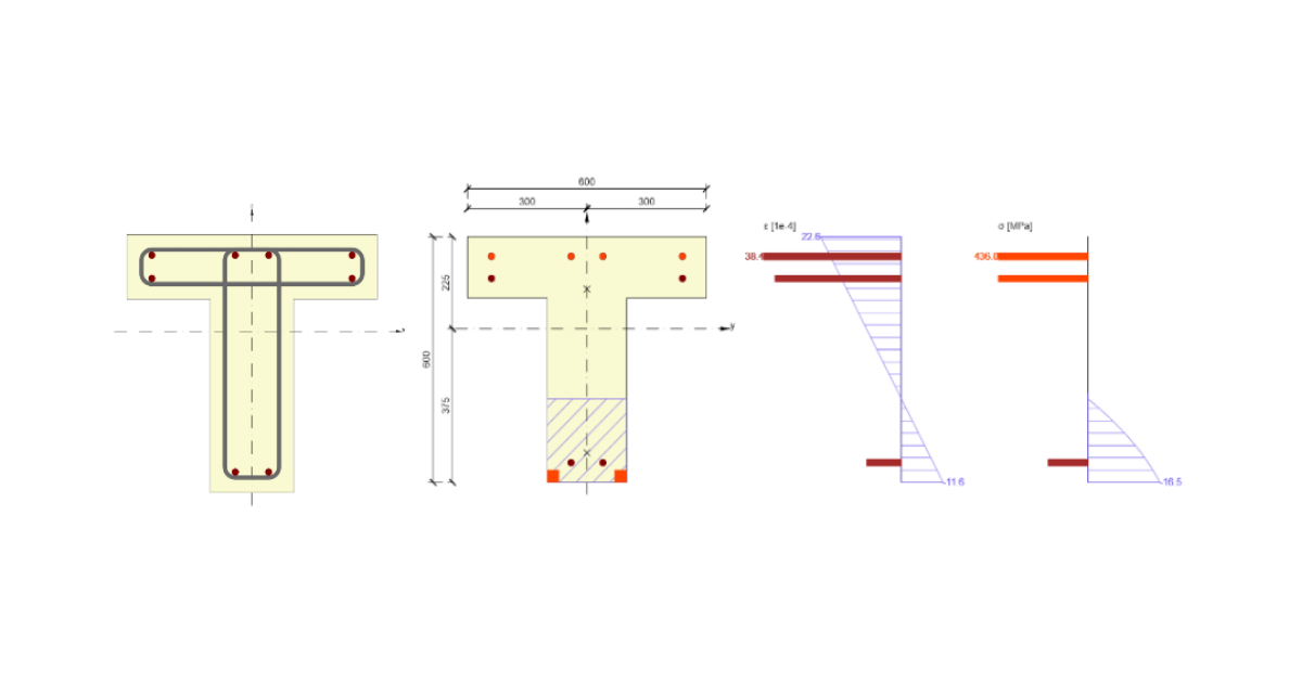
- Concrete
- Tutorials