Reinforced concrete walls – linear or nonlinear design?
As a former structural engineer, I asked myself a question: "Is it really possible to solve any reinforced concrete wall construction in FEA software efficiently, economically, and safely?" After some thought, I decided the best thing to do would be to base my opinion on hard data. So I performed a short experiment.
In the article, I'll show you that using a conservative and noneconomical linear analysis can cause unpleasant troubles with cracks and underestimating concrete in pressure. We will also take a look at optimization and where you can save some material while designing reinforced concrete walls.
In brief, I will compare two approaches to wall design.
- The 2D linear analysis – Materials are defined linearly, you can expect the same behaviour in compression and in tension (That simplification does not correspond to reality, especially for concrete).
- CSFM (Compatible stress field method) – Implemented in IDEA StatiCa Detail. In this type of analysis, you can expect that concrete will be excluded in tension, and the real stiffness of the reinforcement in tension will be used, including crack width calculation.
The case
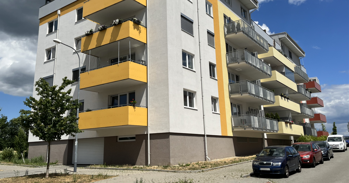
I tried to choose a real case scenario encountered by a larger number of engineers. I focused on a typical multistory building. The first two floors are designed from reinforced concrete walls with openings.
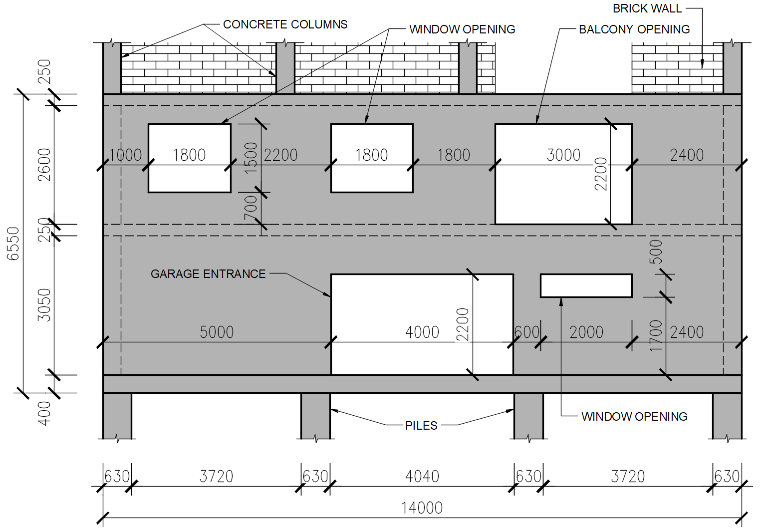
The rest of the structure is a concrete cage (reinforced concrete column + reinforced concrete beam) with masonry walls. For further examination, we will focus on a front wall with a garage entrance. To get a better idea, see the drawing below.
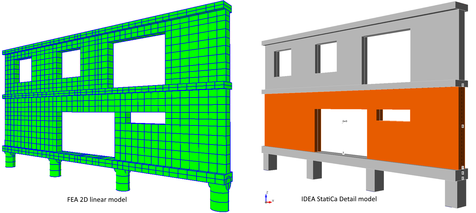
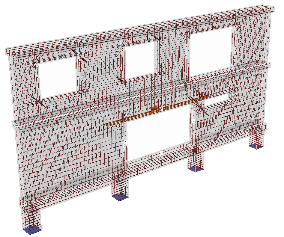
For the comparison, I have created two 2D models. The first one was modelled in FEA software, and the second one in IDEA StatiCa Detail. The model on the left is from FAE software and the model on the right is from Detail.
The models are absolutely identical, and by that, I mean the geometry, boundary conditions, and loads. I am not going to dive into a detailed description of load cases and combinations determination. But to keep you in the loop, you can take a look at the following picture. There, a ULS combination is shown (the values are in kN and kN/m).
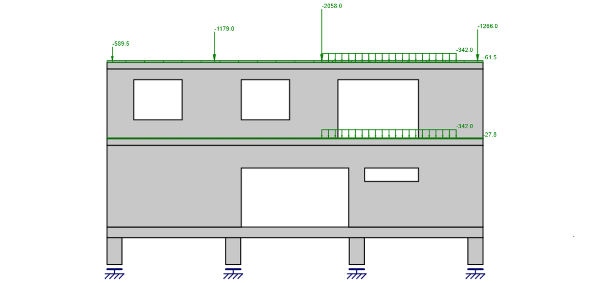
It is worth mentioning the critical force from the middle reinforced concrete and also the loads from balconies. These will have the most significant influence on our design.
Linear 2D analysis design
In this part, I will design the reinforcement and check the concrete based on the results from the linear analysis. I am going to integrate principal tension stress to determine the force that the reinforcement must resist. I will use this approach for the ULS combination, and I will do a crack width check by limiting stress in the reinforcement.
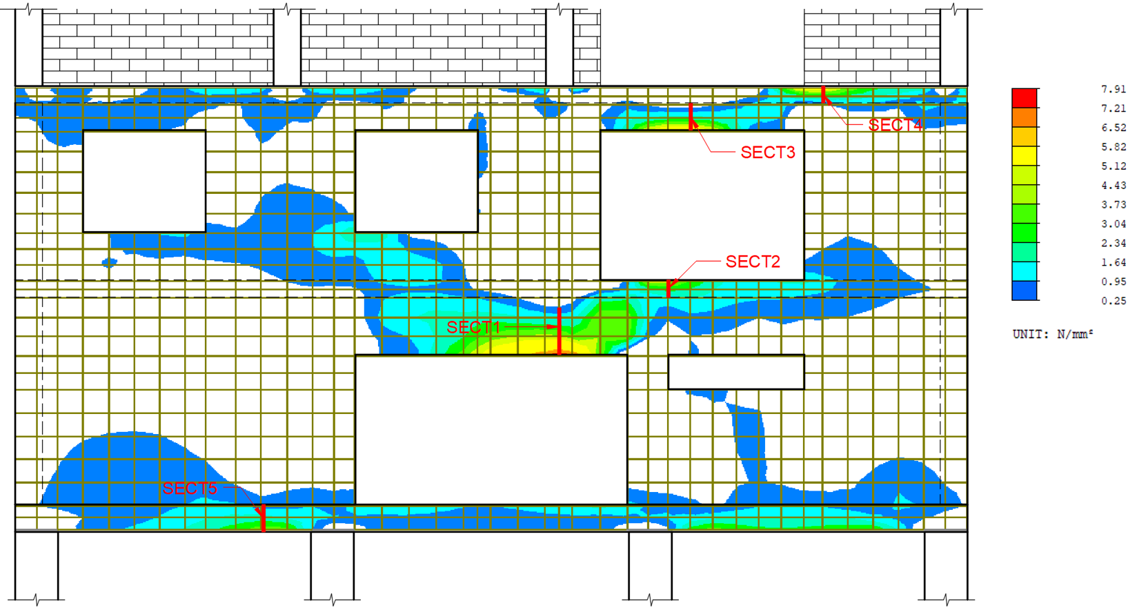
In the following figure, we can see the principal tension stress for the ULS combination and five concrete wall sections, which I will use for reinforcement design.
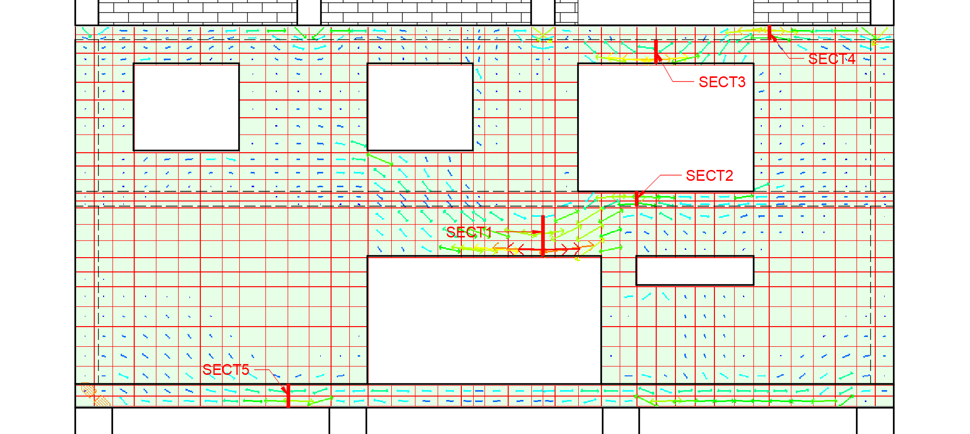
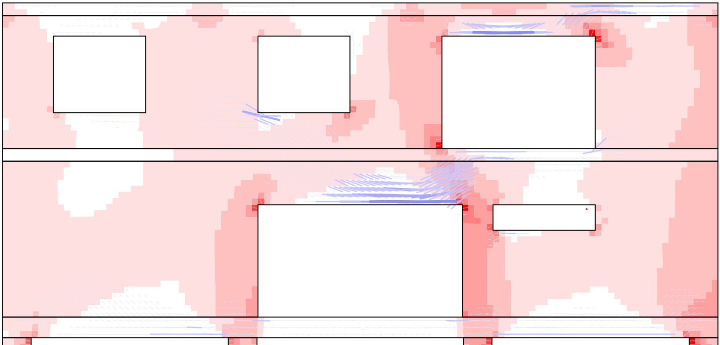
It is also helpful to check the directions (vectors) of the principal stresses to understand the stress flow better. See the figure below to observe the directions of tension.
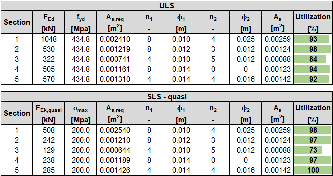
In the following tables, you can see the reinforcement design according to Eurocode. For quasi-permanent combination, the stress in rebars is limited to 200 MPa. It is an analogical approach to EN 1992-2 article 8.10.3 (104).
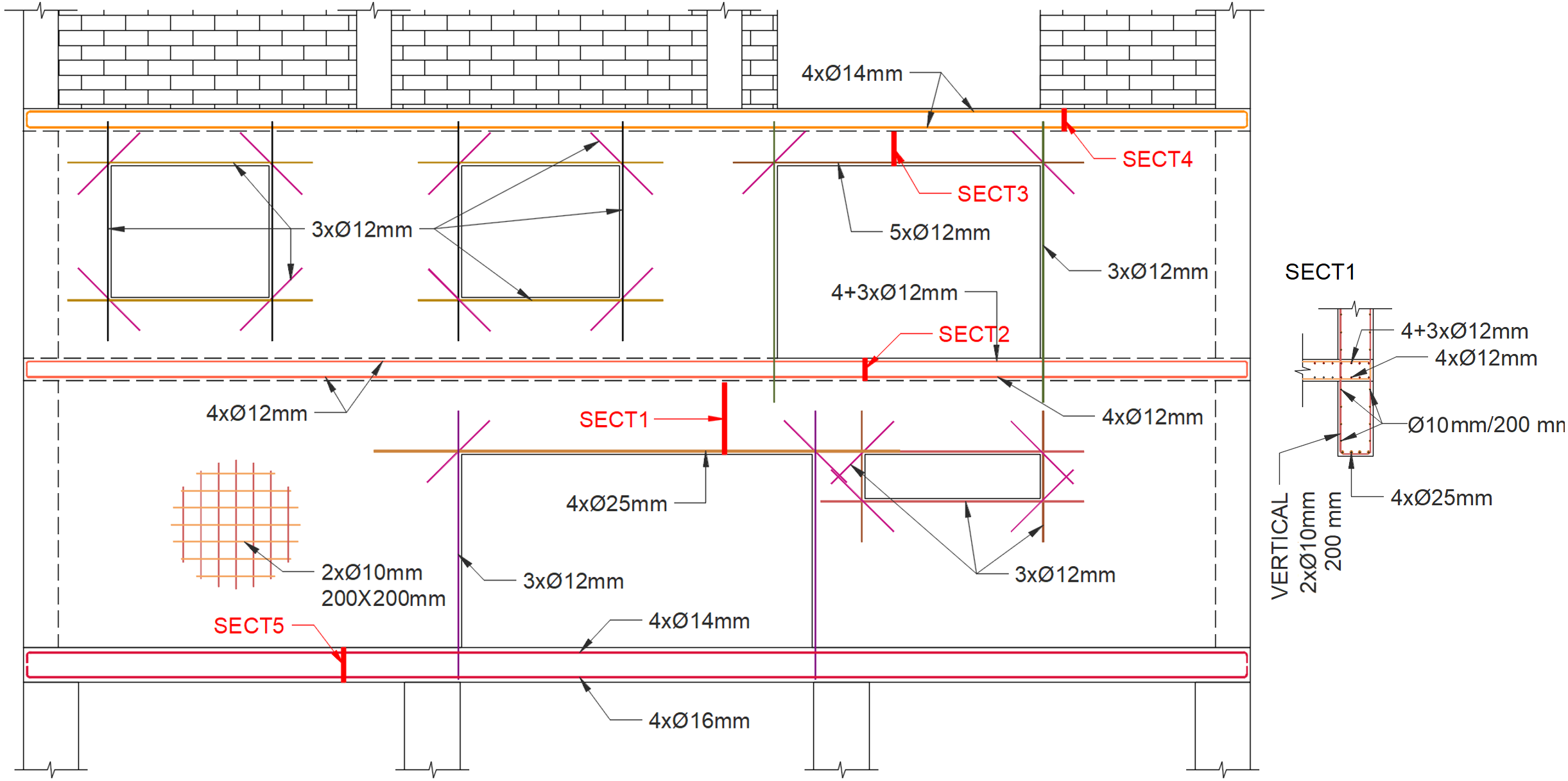
Based on that, I have created a reinforcement scheme that can be sent to the draftsman. I designed the minimum reinforcement of ∅10 mm; 200x200 mm on both surfaces and some additional reinforcement as determined above. The reinforcement above the garage entrance, 4 x ∅25 mm, is especially worth mentioning.
And that's it. The reinforcement design is finished. Now I will just formally check the compression stress in the concrete. I want to design the wall from C25/30, so for ULS, the maximum stress will be fcd = 1.0*25/1.5 = 16.67 MPa (according to EN 1992-1-1, 3.1.6 (1)).
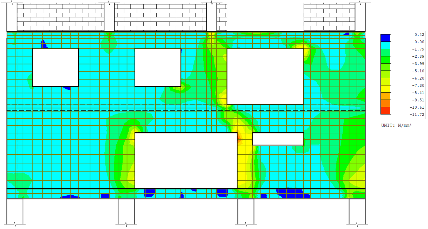
As you can see, there is no problem due to the stress in the concrete. There is only a stress peak in the sharp corner, and even that's lower than the limitation.
At this point, the work for a structural engineer using this method is over. She or he can go home and rest (or start designing other reinforced concrete walls), but we will compare these results with CSFM in IDEA StatiCa Detail (the software that was not only designed as a concrete wall calculator).
IDEA StatiCa Detail design
In IDEA StatiCa Detail, I created the same model of reinforced concrete wall construction (including the designed reinforcement) as you could see in the previous paragraph.
Before running the calculation itself and comparing the results in each concrete wall section, let's use another design tool – linear analysis, which is a predesign tool. The results show us the conformity of models. You can see that the directions (vectors) of the principal tensional stresses are the same as well as the concrete in compression.
Ok, one could say the job is done...
But wait a minute! I run the analysis and the program shows me that the whole portion of the load for the ULS combination cannot be applied! And it seems that it failed because of the strength of the concrete! But it was ok with my conservative linear approach. What's going on here?
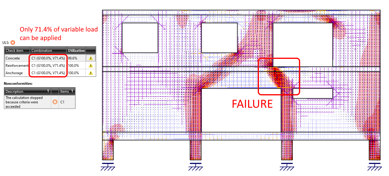
Actually, the reason why it failed is the compression softening effect. Basically, it means that the strength of concrete affected by transverse cracks is lowered.
Try to recall the directions (vectors) of the principal tensional stresses. In the critical area, the crack causing tension is perpendicular to the compression strut. This effect is, for example, introduced for the strut and tie method for nodes in EN 1992-1-1, 6.5.4 as k1, k2, and k3 factors, or in ACI 318-19, 23.9.2 as βn factor.
In IDEA StatiCa Detail, we introduce this effect as the kc2 factor for each finite element. So, for our example, the map of the compression softening effect looks like this:
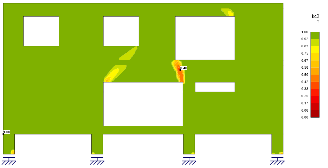
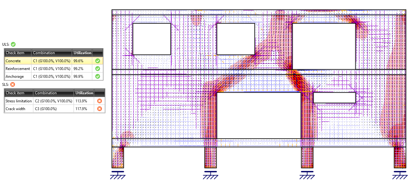
Ok, what does it mean for us? We need to increase the concrete grade from C25/30 to C30/37 and recalculate the model. With this modification, the results for ULS look ok. The whole portion of the load can be applied, and the ULS checks are a pass.
- More information about ULS checks in General description of ULS results in Detail application
But, there is another problem, this time with SLS checks. Cracks and stress limitation is not sufficient. Again, how can there be a problem with cracks?! We used a conservative method to design the reinforcement.
- More information about SLS checks in General description of SLS results in Detail application
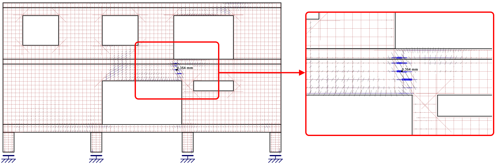
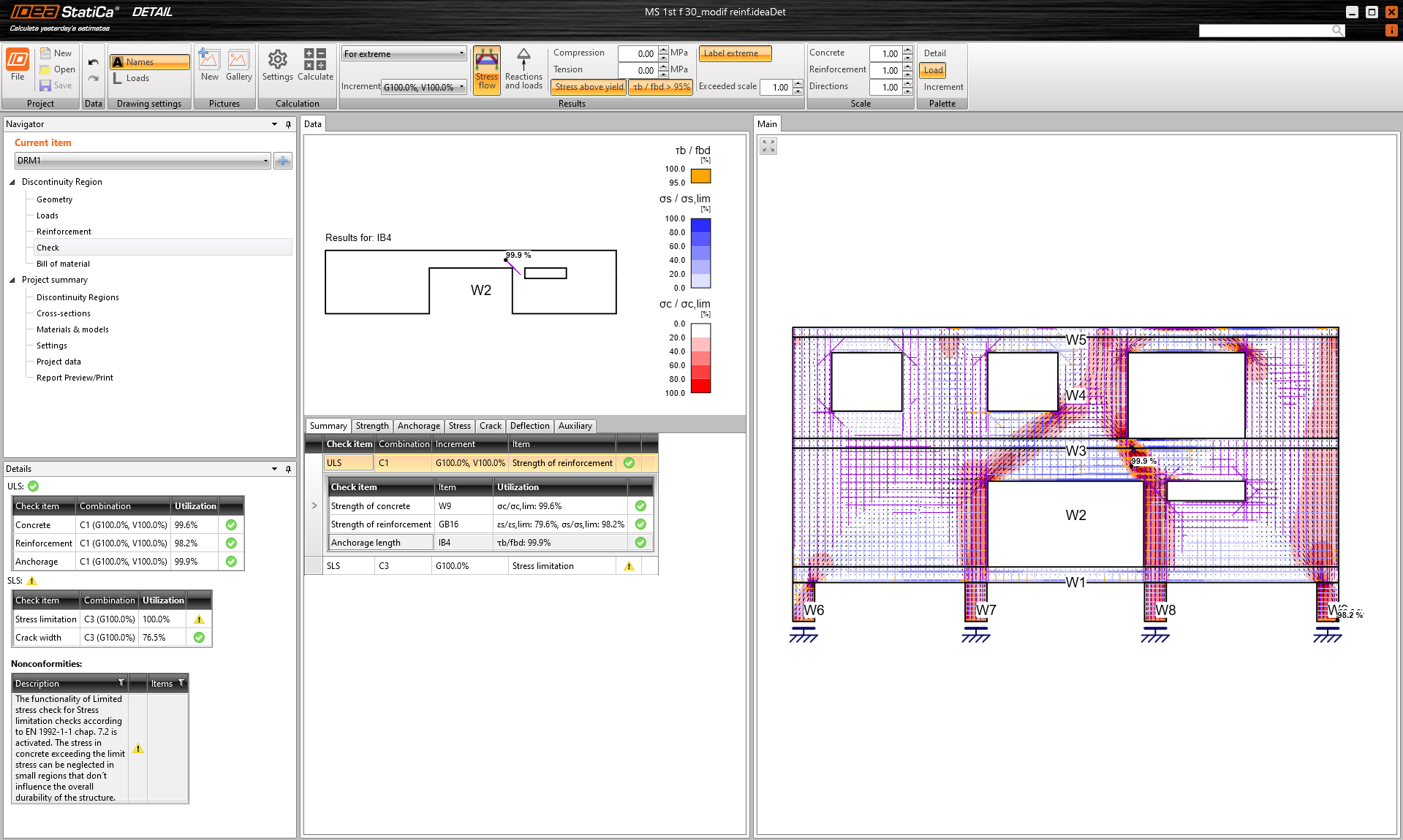
It seems that despite the fact that we designed a relatively strong reinforcement above the garage opening, cracks have formed in the space between the ceiling and the opening, where only a reinforcement made of a 10 mm profile is designed. The picture also shows that the strong reinforcement above the opening is not particularly used.
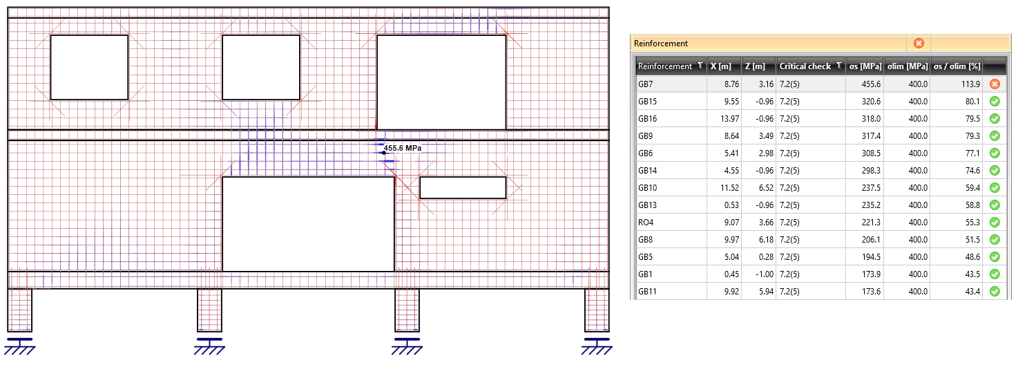
If we look at the stress in reinforcement for SLS – a characteristic combination, we will see that the same situation with low utilization is, for example, above the balcony opening (section 3). And we can also see the reason why the stress limitation check is insufficient. It is because the σlim = 400 MPa.
Now what are the options? We can decrease reinforcement in sections 1, 3, and 5. But, on the other hand, we need to add something to the critical area.
There are the changes:
- Section 1 - 4x∅25 => 4x∅16
- Section 3 - 5x∅12 => 3x∅12
- Section 5 - 4x∅16 => 4x∅14
- Section 1 - +2x4x∅14
After adding 2x4 rebars 3.0 m long between the ceiling and the garage opening, and reducing the mentioned above, all checks are OK. We can go home and rest, as well as the structural engineer that used the linear method. But, we will likely rest for a longer time because we probably will not have trouble explaining why cracks above the garage opening appear.
Conclusion
There were significant differences between these two approaches. In the linear 2D method, we underestimated the concrete, overestimated some reinforcement, and didn't detect a potential crack location. The culprit is the incorrect redistribution between tension (reinforcement) and compression (concrete) in the linear model.
So, to answer the first question of this article. No, it is not possible to solve any reinforced concrete wall construction in your FEA software efficiently, economically, and safely. It is much better to use a more sophisticated concrete wall calculator such as the IDEA StatiCa Detail with CSFM implemented in it.
- Watch the webinar Code-check of walls and deep beams
One final note I want to share with you. I must admit that originally, I wanted to offer you a comparison between the three methods. Linear 2D, CSFM, and strut and tie. But the lastly named method is so time-consuming that I was not able to create a sufficiently working model before I wanted to publish this blog post.
Download the new version of IDEA StatiCa and try all the features