Managing change when using IDEA StatiCa Connection
Introduction
A very big issue that has faced the whole construction industry is how change is managed or communicated. Here at IDEA StatiCa, we are working on several methods to help facilitate this. Historically, we have had DXF output for plates and DWG from our Viewer application, but getting information back into a BIM solution has been somewhat lacking – until now!
From this current release (23.1), we have been able to create a compliant IFC file and import this into Revit, Tekla Structures, SDS2 and any viewer that has an IFC import option. However, there are differences between all of these receiving solutions that I will also highlight in this article. Not only in the workflow, but also in the end result.
Historically
Many engineers have been educated to use analog methods: 2D drawings and sketches that were created either by hand (often considered works of art now) or by CAD solutions (such as AutoCAD). Many a time, these were initially created by the person who wanted the information, so they were realistically created from a modeling solution (such as Tekla Structures) but the information received back was in the form of their drawing/sketch, but heavily red-lined annotated! Then to ensure that the changes were incorporated correctly, these were marked off in blue with green being the final check – other colours are available! These sketches and markups would also form part of the quality-checking process, especially true when conforming to ISO 9001.
As time progressed, these analog methods were digitalized into the magic of a marked-up PDF document. Still red though!
With the advent of BIM and other ISO 19650 workflows, there was a greater need for greater cooperation that could be audited if required. Many governments are now mandating these workflows, which makes them even more important.
Another consideration is repeatability. Given the rate of change of software and their versions, it is very apparent that today's native files will be out of date unless there is a common format they can all use that will remain fairly static – this is where IFC (Industry Foundation Class) comes into the fray.
In conjunction with IFC, there is another open format called BCF which allows comments and changes to be associated with the object that needs amending. In addition, views can also be saved of this object within the file. This relies on an IFC viewer (at least) that allows markup and BCF export to enable the original application to read these to give the end user a smooth and managed workflow to make the change.
Customers have even taken screenshots of proposed connections and incorporated these into their drawings - Curragh Racecourse, Newbridge, Ireland – is a case study in point.
Our approach
Here at IDEA StatiCa, we have always placed great importance on being able to document the design. We have had 2D DXF output for plates for several years now.
Our Viewer technology is able to produce 3D DWG files. Both can be consumed by any solution that can read DXF/DWG and, hence, documented.
Most recently for our 23.1 release, we included IFC export. IFC is a format that the construction industry uses to exchange information – not just small nuggets of information but more often than not, whole models. Their size varies (obviously) from a few KB to several hundred MB. Luckily for the users of IDEA StatiCa Connection, ours fall into the former bracket!
Using our 3D print example 3D Connection Model | IDEA StatiCa, we can compare various outputs.
Opening this in our Viewer, you can see that we have access to both 3D DWG and IFC.
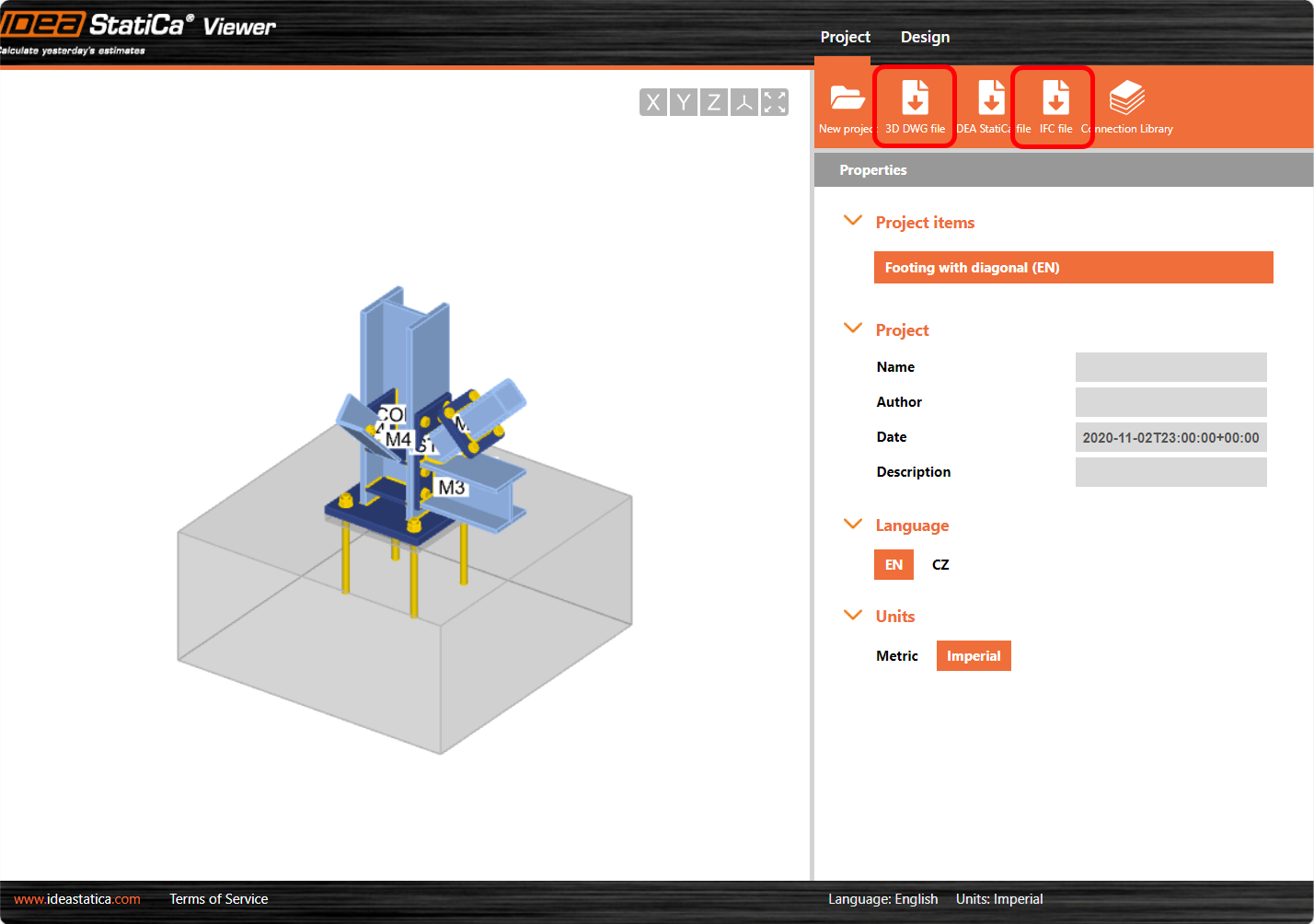
What do these resultant files look like and, more importantly, what can you do with them?
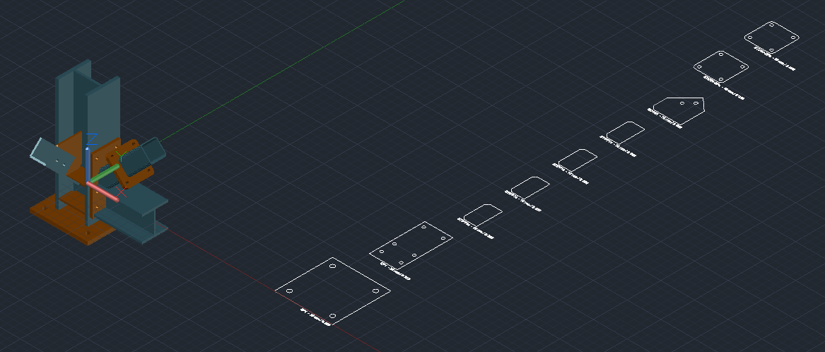
DWG/DXF
Opening the DWG file in AutoCAD, we see a series of 2D plate outlines and 3D solids representing the actual members and plates (there are no fasteners though) arranged as they would be in the connection project. Using this information, it is very easy to create documentation to convey the design intent of the project.
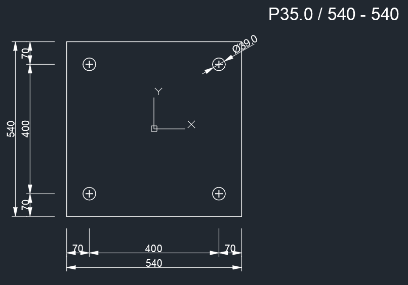
When opting for DXF output, you can create individual files for each plate in the project, which you access via the Plate Editor function.
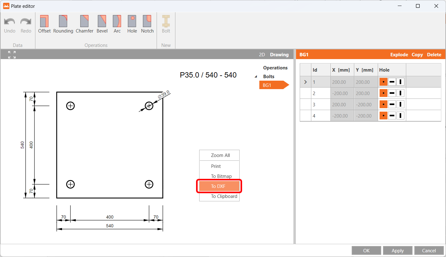
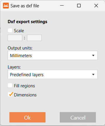
Creating a DXF file is easy and there are several options to fine-tune the output. There still might be additional work required in the receiving solution (generally AutoCAD), but nonetheless, it is a good way to get individual plates into a drawing for documentation and even, possibly, ready for fabrication.
IFC
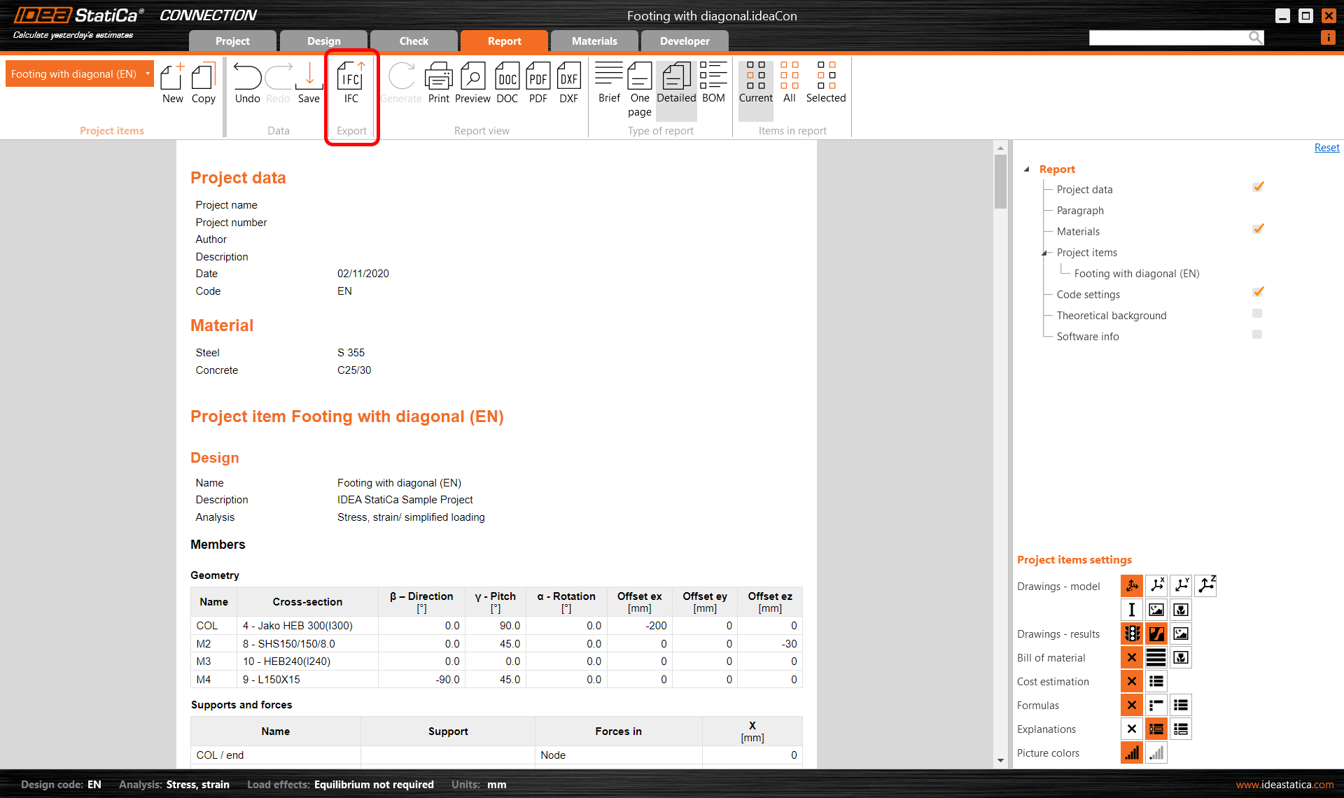
Opening the native file in IDEA StatiCa Connection and navigating to the Report tab, we are again given the option to export to IFC.
There are several solutions that can read the IFC file – these usually fall into the BIM arena: Revit, Tekla Structures, SDS2 and many other ‘readers’ such as BIMvision, Solibri, Navisworks, plus several cloud-based platforms such as Bimplus and Trimble Connect. They all work differently and have varying degrees of success, depending on how accomplished they are at reading ‘compliant’ IFC files!
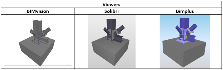
This is an example of how using this format will inform others as to the overall appearance and makeup of a particular project. Not only is there a graphical representation of the object but there is also lots of information attached to these objects as well, such as thickness, diameter, material grade, etc. Depending on the level of service the end user opts for, there may or may not be the facility to annotate these IFC files with comments. This is particularly helpful when someone is interested in feedback before developing a connection – say requesting additional engineering (or heaven forbid – architectural) input 😊.
However, these are ‘viewers’ and are not that constructive when you want to convey changes where using a modeling approach would work better. This is where it gets really interesting!
The BIM solutions that we support via our BIM links also support the IFC workflow.
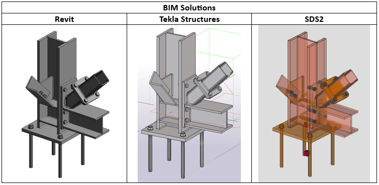
Some solutions are able to ‘map’ the generic solids to be a particular class, others do that automatically. This means that intelligence can be added to the dumb solids, making them really useful! Not only can views be created but the objects can be dynamically annotated and dimensioned (obviously).
Wrapping up
Is there one solution that we would recommend? Definitely not. They all have their quirks and it would be wrong of us to make such a recommendation. We have only just started on this IFC journey and I feel there is more to come. Why not join us?
Try IDEA StatiCa for free