Release notes IDEA StatiCa Steel 20.1
Introducere
Noua versiune IDEA StatiCa este disponibilă!
Indiferent dacă utilizați IDEA StatiCa ca aplicație independentă sau prin legături BIM cu aplicații FEA/CAD, versiunea 20.1 va accelera dramatic proiectarea îmbinărilor dumneavoastră. Toate acestea cu accent pe posibilitatea inginerilor de a evalua temeinic cerințele codului național și de a utiliza cantitatea optimă de material.
Principalele noutăți ale acestei versiuni sunt:
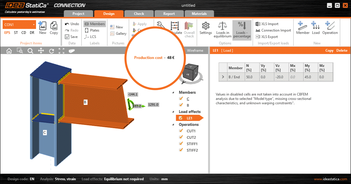
- Estimarea costurilor - aflați cât va costa îmbinarea, în timp real în scena 3D, pe baza datelor de fabricație.
- Pre-proiectare - motorul IDEA StatiCa modelează proactiv părți ale îmbinărilor pentru dumneavoastră, accelerând procesul de optimizare a proiectelor pentru a obține cele mai bune rezultate.
- Selecție în masă a îmbinărilor din Tekla, Advance Steel, Revit - nu mai este nevoie să selectați îmbinările una câte una în 3 pași. Trageți pur și simplu peste 10 îmbinări în Tekla și IDEA StatiCa le exportă automat. Modificări în Tekla? Faceți clic pe „Sincronizare totală".
Pe lângă acestea, am pregătit câteva îmbunătățiri la licențierea IDEA StatiCa pentru a vă permite o gestionare flexibilă și confortabilă a licențelor.
Sperăm că vă vor plăcea toate noile funcționalități și îmbunătățiri și așteptăm cu drag feedback-ul dumneavoastră oricând.
Calculați estimările de ieri!
IDEA StatiCa Connection improvements
Estimarea costurilor
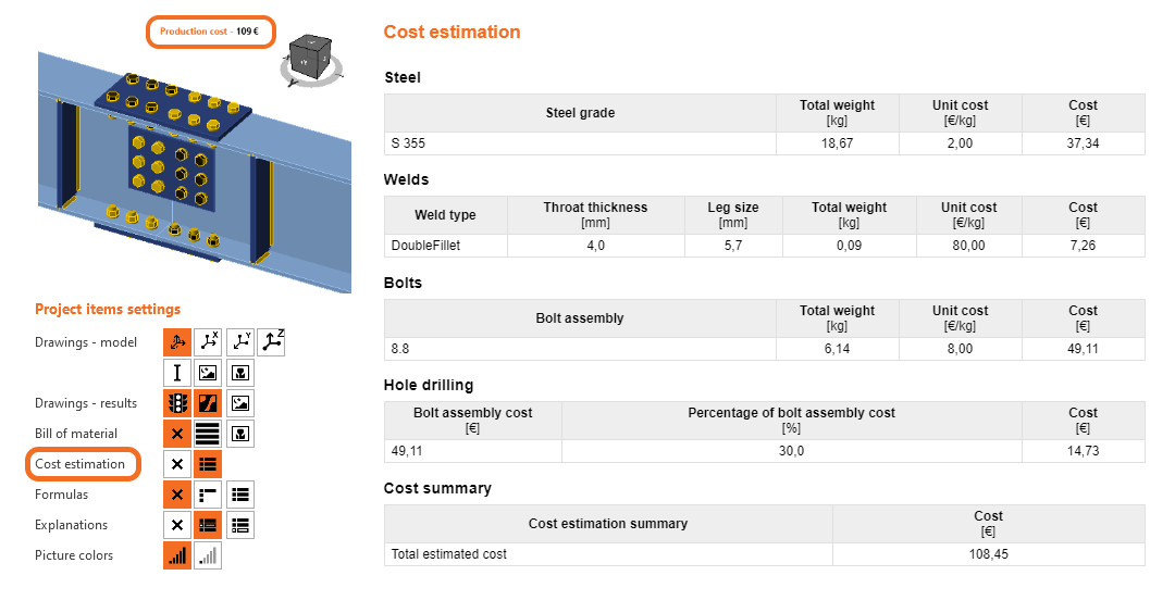
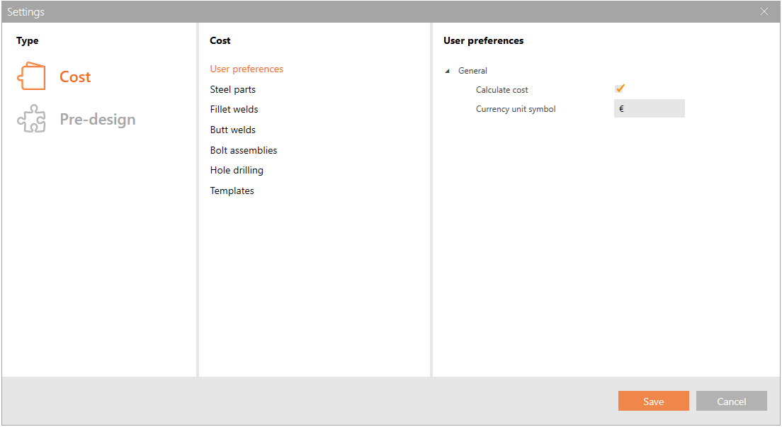
Prețurile componentelor individuale ale îmbinării pot fi specificate pe baza costului per unitate de greutate în Setări. Costurile pot fi definite în prezent pentru patru entități de bază:
- Piese din oțel (plăci și elemente din oțel adăugate, în funcție de marcă)
- Suduri (suduri de colț simple și duble, suduri cap la cap ½ V și K, în funcție de dimensiunea sudurii)
- Ansambluri de șuruburi (în funcție de marcă și diametru)
- Găurire (ca procent din costul ansamblului de șuruburi)
Valoarea rezultată este prezentată în scena 3D și este actualizată în funcție de operațiile de fabricație utilizate în proiect. Calculul detaliat al costurilor este o parte opțională a raportului de calcul.
Vedeți cum funcționează
Urmăriți partea din înregistrarea webinarului în care colegul nostru Ryan prezintă funcția de estimare a costurilor.
Disponibil în ediția Expert și Enhanced .
ARTICOLE CONEXE
Proiectare preliminară a îmbinării
Acest articol conține informații depășite. Vă rugăm să consultați versiunea actualizată.
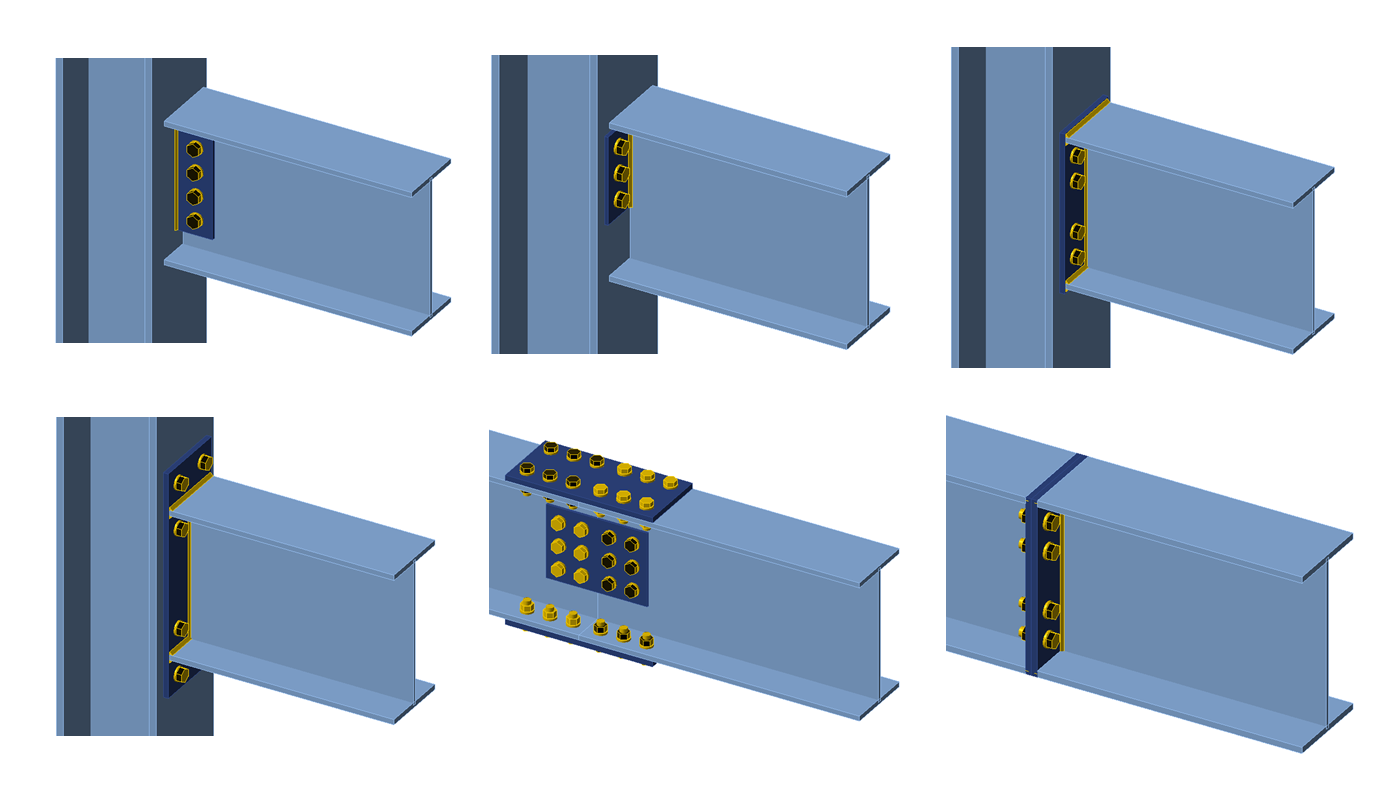
Funcția se află într-un stadiu incipient și a fost implementată în principal pentru secțiuni transversale în formă de I, acestea fiind cele mai frecvente operații de fabricație:
- Placă de inimă
- Înnădire
- Placă de capăt la forfecare
- Placă de capăt îngropată și extinsă
- Suduri
Cum funcționează?
Proiectarea preliminară citește datele de intrare din tabelul de proprietăți al operației de fabricație date și creează apoi un proiect inițial sugerat. În general, datele materiale și geometrice ale elementelor conectate, ansamblul de șuruburi și datele de sudură sunt citite ca date de intrare pentru procesul de proiectare preliminară. Ca rezultat (ieșire), sunt generate grosimea plăcii, dimensiunile sudurilor, numărul și dispunerea șuruburilor.
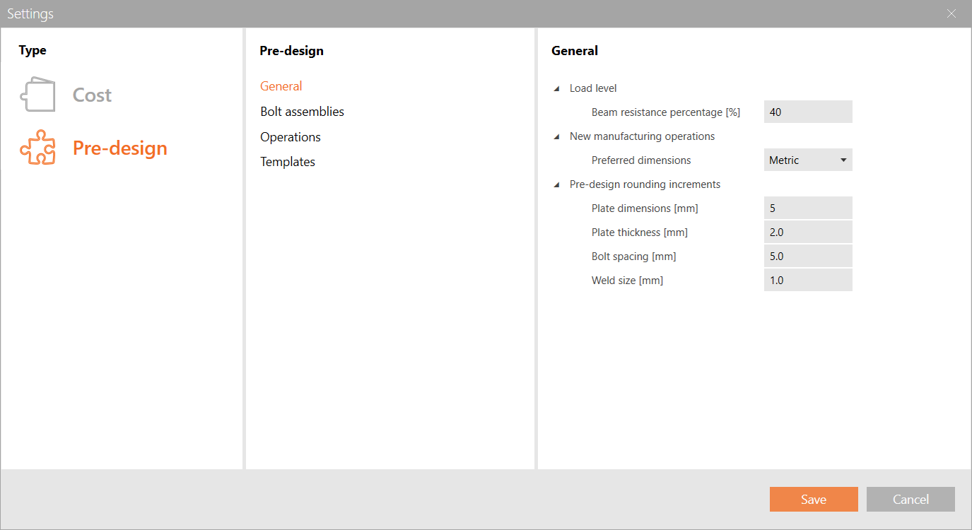
Proiectul rezultat se bazează aproximativ pe rezistența secțiunilor transversale sau a plăcilor conectate. Procentul din această rezistență poate fi modificat în setările de proiectare preliminară (bara de instrumente superioară). Un procent mai mare va genera proiecte mai robuste.
Există și alte preferințe pe care le puteți modifica în Setări, inclusiv incrementele de dimensiune preferate pentru grosimile plăcilor, dimensiunea sudurii și distanța dintre șuruburi.
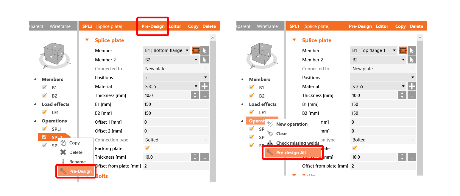
În cazul în care o operație dată este acceptată, puteți apela proiectarea preliminară făcând clic dreapta pe numele operației în arborele de operații sau făcând clic pe butonul din fila portocalie din partea superioară a grilei de proprietăți a operației. Proiectarea preliminară este apelată și automat la crearea unei noi operații. De asemenea, este posibil să obțineți proiectarea preliminară în lot pentru toate operațiile acceptate, făcând clic dreapta pe Operații în arbore.
Disponibil în ediția Expert și Enhanced .
Dialogul de setări
Noua versiune a fost îmbogățită cu un nou buton în bara de instrumente superioară care deschide dialogul de Setări. În acest dialog, două noi funcționalități principale ale versiunii 20.1 pot fi ajustate: Calculul estimării costurilor și Pre-dimensionarea îmbinării.
Dialogul de Setări vine cu o funcționalitate de șablon care permite salvarea valorilor introduse într-un șablon, încărcarea valorilor din diferite șabloane și selectarea unui șablon implicit pentru proiecte noi. Șabloanele sunt specifice diferitelor funcționalități și sunt, de asemenea, specifice codului de proiectare.
Expertul pentru Îmbinări Noi
În secțiunea Design a expertului, variantele propuse sunt grupate în funcție de comportamentul așteptat al îmbinării: îmbinări la moment, îmbinări la forfecare și îmbinări pentru structuri cu zăbrele. Desigur, opțiunea de a începe cu un proiect gol este păstrată de asemenea.
Toate acestea vă vor ajuta să accelerați procesul de selectare a șablonului și să îmbunătățiți cunoașterea proprietăților îmbinării.
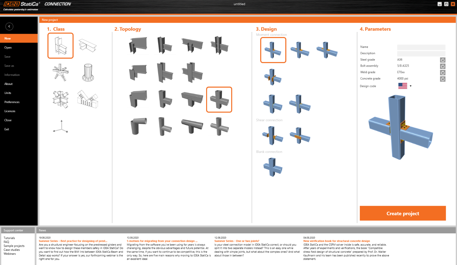
Ordinea șabloanelor în secțiunea Design depinde de selecția codului, de exemplu, ordinea șabloanelor Design pentru codul AISC este diferită față de codul EN și altele.
Disponibil în ediția Expert și Enhanced .
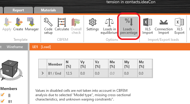
Încărcare procentuală
O nouă opțiune simplă pentru setarea efectelor de încărcare a fost adăugată în IDEA StatiCa Connection 20.1. Elementele pot fi încărcate cu un procent definit din capacitatea secțiunii transversale. Setarea încărcărilor ca procent din capacitatea secțiunii transversale este destinată în principal ca un instrument simplu. Setarea încărcărilor în echilibru este preferată.
Proprietățile secțiunii transversale pot fi vizualizate în fila Materiale. Torsiunea este dezactivată deoarece rezistența elementului la torsiune nu poate fi determinată clar din cauza constrângerilor de încovoiere neuniformă necunoscute.
Forțele interioare pentru efectele de încărcare se calculează după cum urmează:
- Încărcare axială:
- \(N=A \cdot f_y / \gamma_{M0}\)
- Încărcare de forfecare:
- \(V_z =\frac{A_z \cdot f_y}{\sqrt{3} \cdot \gamma_{M0}}\)
- \(V_y =\frac{A_y \cdot f_y}{\sqrt{3} \cdot \gamma_{M0}}\)
- Moment încovoietor:
- \(M_y = W_{el,y} \cdot f_y / \gamma_{M0}\)
- \(M_z = W_{el,z} \cdot f_y / \gamma_{M0}\)
Rețineți că \(\gamma_{M0}\) este un factor parțial de siguranță al materialului și denumirea sa poate diferi între coduri. De asemenea, rețineți că unele coduri, cum ar fi AISC, utilizează valori ușor diferite pentru încărcarea de forfecare, de ex. 0,6. Cu toate acestea, în IDEA StatiCa Connection, formulele urmează criteriul de curgere von Mises și sunt aceleași pentru toate codurile.
Disponibil în ediția Expert și Enhanced .
Distanțe de rezemare pentru buloane conform Eurocode
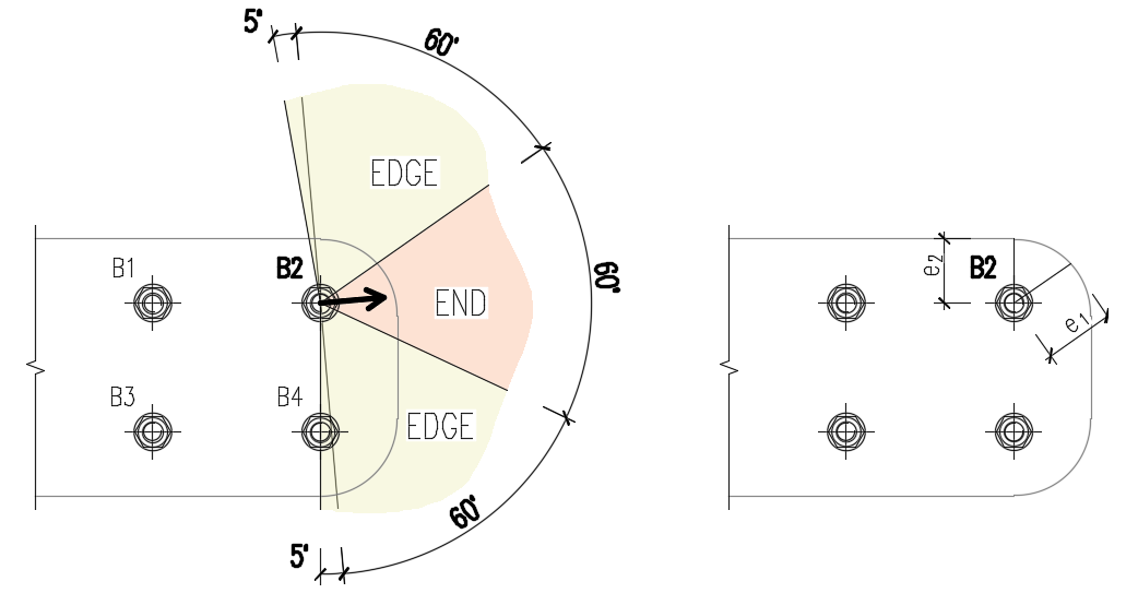
Noua versiune aduce un algoritm îmbunătățit pentru calculul distanțelor dintre buloane (p1; p2), de capăt (e1) și de margine (e2) pentru verificarea la rezemare conform Eurocode. Această îmbunătățire este relevantă în special pentru geometrii generale ale plăcilor, plăci cu goluri, decupaje etc.
Algoritmul citește direcția reală a vectorului forței tăietoare rezultante într-un buloan dat și calculează apoi distanțele necesare pentru verificarea la rezemare.
Distanțele de capăt (e1) și de margine (e2) sunt determinate prin împărțirea conturului plăcii în trei segmente. „Segmentul de capăt" este indicat de un interval de 60° în direcția vectorului forței. „Segmentele de margine" sunt definite de două intervale de 65° perpendiculare pe vectorul forței. Cea mai scurtă distanță dintre un buloan și o margine în segmentul relevant este apoi considerată ca distanță de capăt sau de margine.
Algoritmul evaluează toate plăcile conectate de buloan — plăcile de îmbinare (de ex., o placă de eclisă), plăcile elementului (de ex., o talpă superioară) — și se utilizează cea mai scurtă distanță.
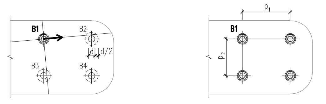
Distanțele dintre găurile buloanelor (p1; p2) sunt determinate prin mărirea virtuală a găurilor buloanelor din jur cu jumătate din diametrul lor, apoi trasând două linii în direcția vectorului forței tăietoare și perpendicular pe acesta. Când aceste linii intersectează găurile buloanelor mărite virtual, distanțele față de aceste buloane sunt considerate ca p1 și p2 în calcul.
Dacă liniile nu intersectează bulanul cel mai apropiat vizual (chiar dacă linia trece aproape de buloan), acest buloan este neglijat. Dacă liniile nu intersectează niciun buloan, se utilizează o valoare infinită.
Disponibil în edițiile Expert și Enhanced .
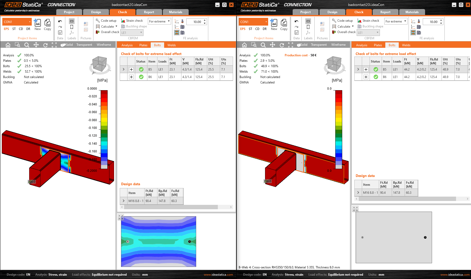
Un model îmbunătățit al contactelor
Modelul de analiză conține mai multe neliniarități, printre care și contactele dintre plăci. Contactele sunt foarte rigide la compresiune și extrem de slabe la întindere.
Cu toate acestea, o anumită rigiditate este necesară chiar și la întindere pentru a asigura stabilitatea numerică a modelului. Au existat câteva cazuri foarte rare cu o zonă de contact mare și o deformație mare la întindere, în care forța de întindere din contacte consuma o parte semnificativă din încărcarea aplicată.

Modelul de contact a fost îmbunătățit pentru a menține stabilitatea analizei numerice și pentru a limita forța de întindere din contact la un nivel neglijabil.
Disponibil în edițiile Expert și Enhanced .
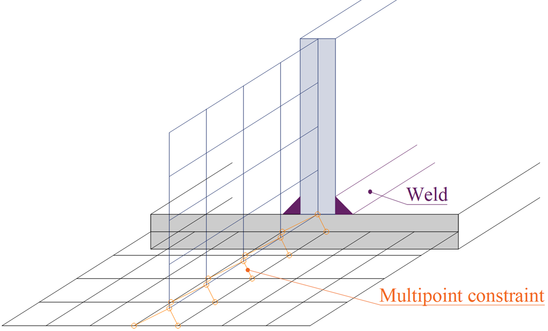
Sudură cap la cap - model îmbunătățit
Anterior, era selectată grosimea celei mai subțiri dintre plăci. Acum, este selectată grosimea plăcii a cărei margine este utilizată. Acest lucru poate avea un impact foarte mic asupra rezultatelor într-un număr neglijabil de modele mai vechi, datorită modificării constrângerilor multipunct în modelul de analiză. Când se utilizează sudura cap la cap mai mare, constrângerea multipunct transferă forța într-o zonă mai mare pe suprafața plăcii conectate.
Disponibil în ediția Expert și Enhanced .
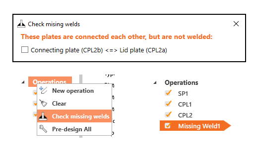
Verificarea sudurilor lipsă
Instrumentul identifică și listează plăcile și marginile de placă relevante și permite adăugarea sudurilor lipsă.
Puteți accesa această funcționalitate prin clic dreapta pe Operații în arborele de entități din partea dreaptă a scenei.
Disponibil în ediția Expert și Enhanced .
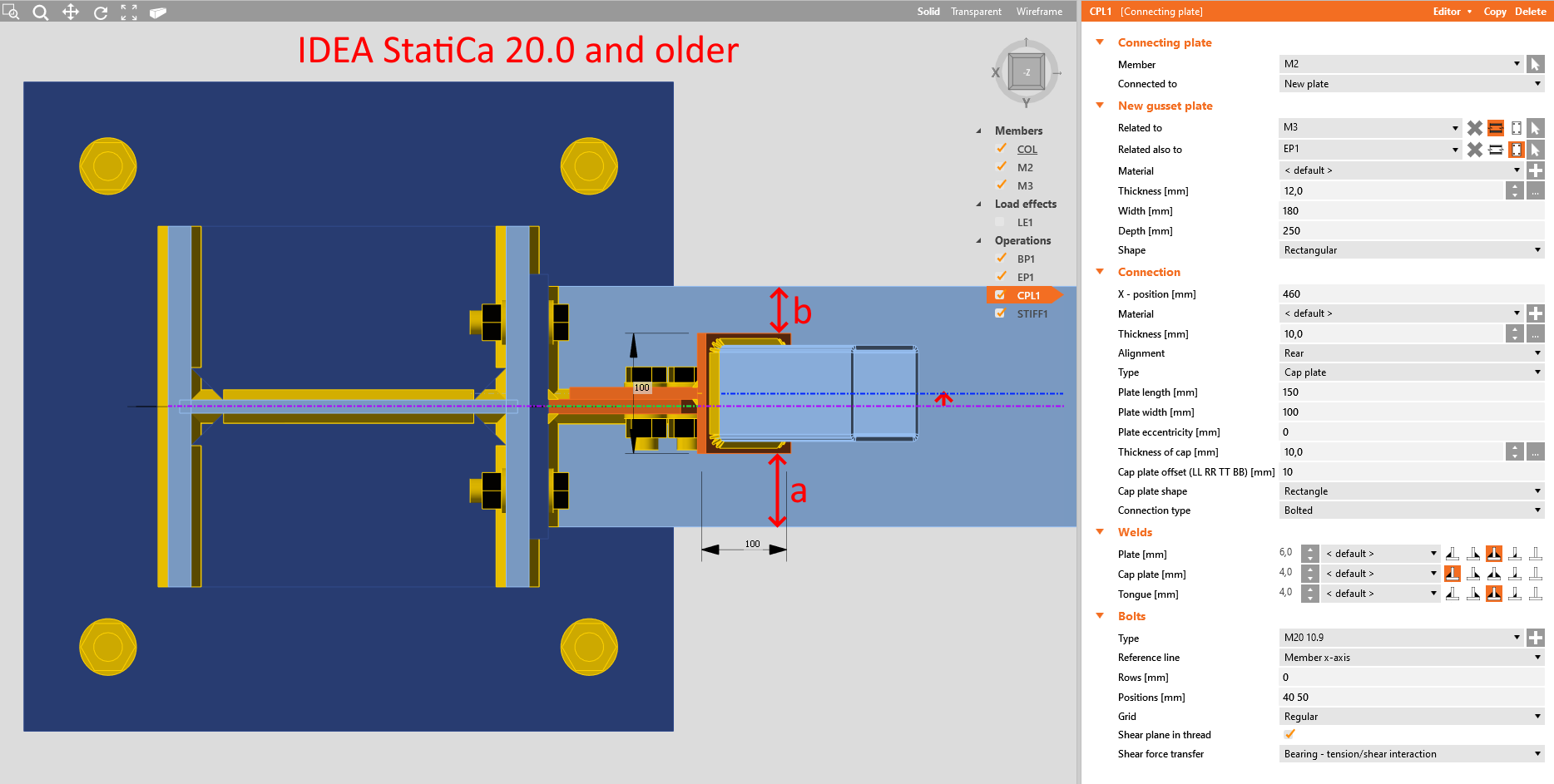
Excentricitatea plăcii de îmbinare
Poziția elementului conectat în cadrul operației Plăci de îmbinare a fost modificată în versiunea 20.1. Această modificare a fost efectuată datorită asamblării întregului model în aplicația Connection și a dezvoltării ulterioare a interoperabilității cu aplicația Member.
În versiunea 20.0 și versiunile anterioare, elementul conectat era deplasat atunci când se aplica operația Placă de îmbinare, astfel încât axa elementului era centrată cu placa de legătură, în timp ce placa de îmbinare era centrată cu axa elementului de reazem.
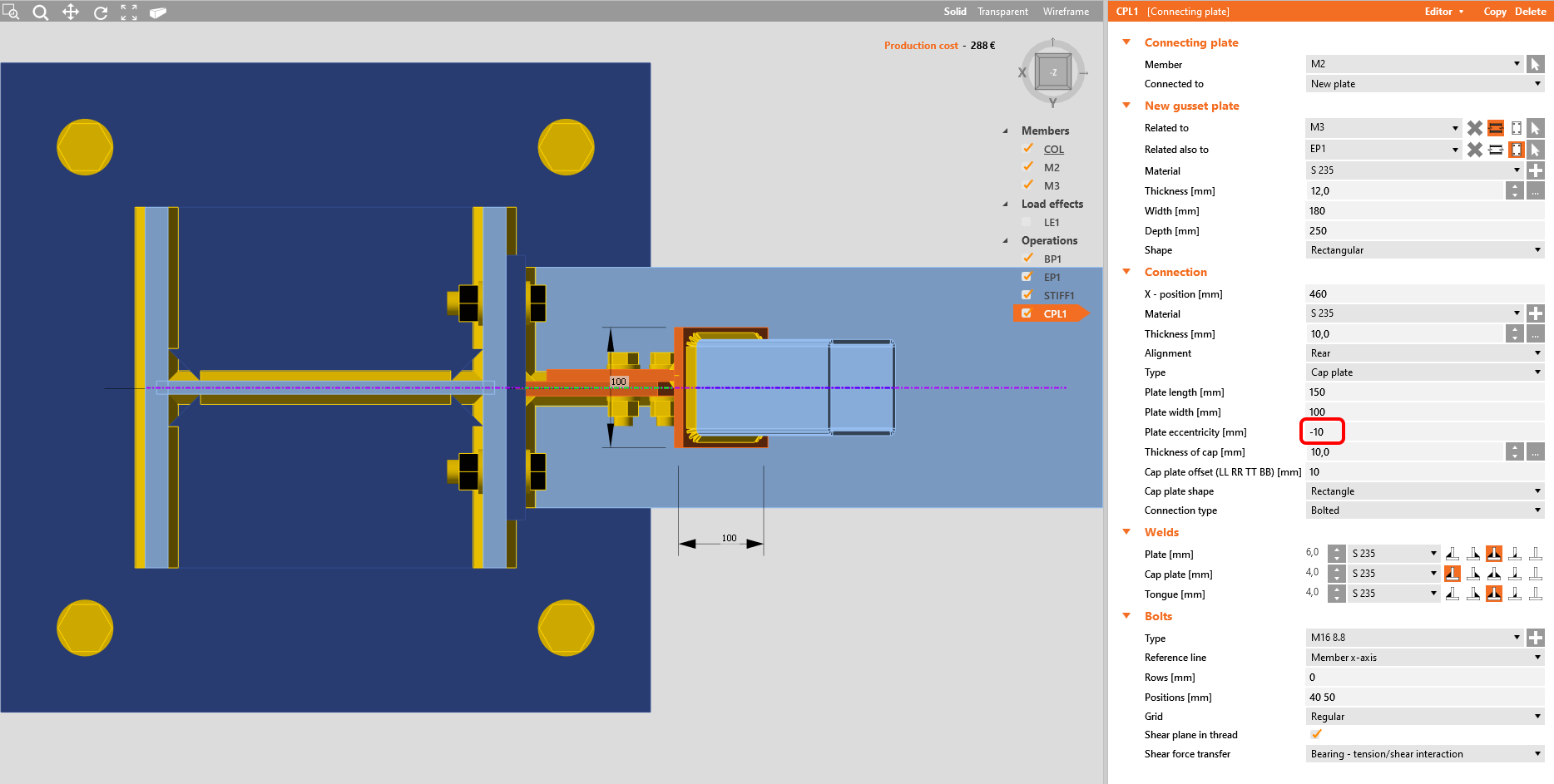
În versiunea 20.1 și versiunile mai noi, elementul conectat nu mai este deplasat pentru a-și păstra poziția, ceea ce înseamnă că placa de îmbinare este acum deplasată și nu mai este centrată cu axa elementului de reazem.
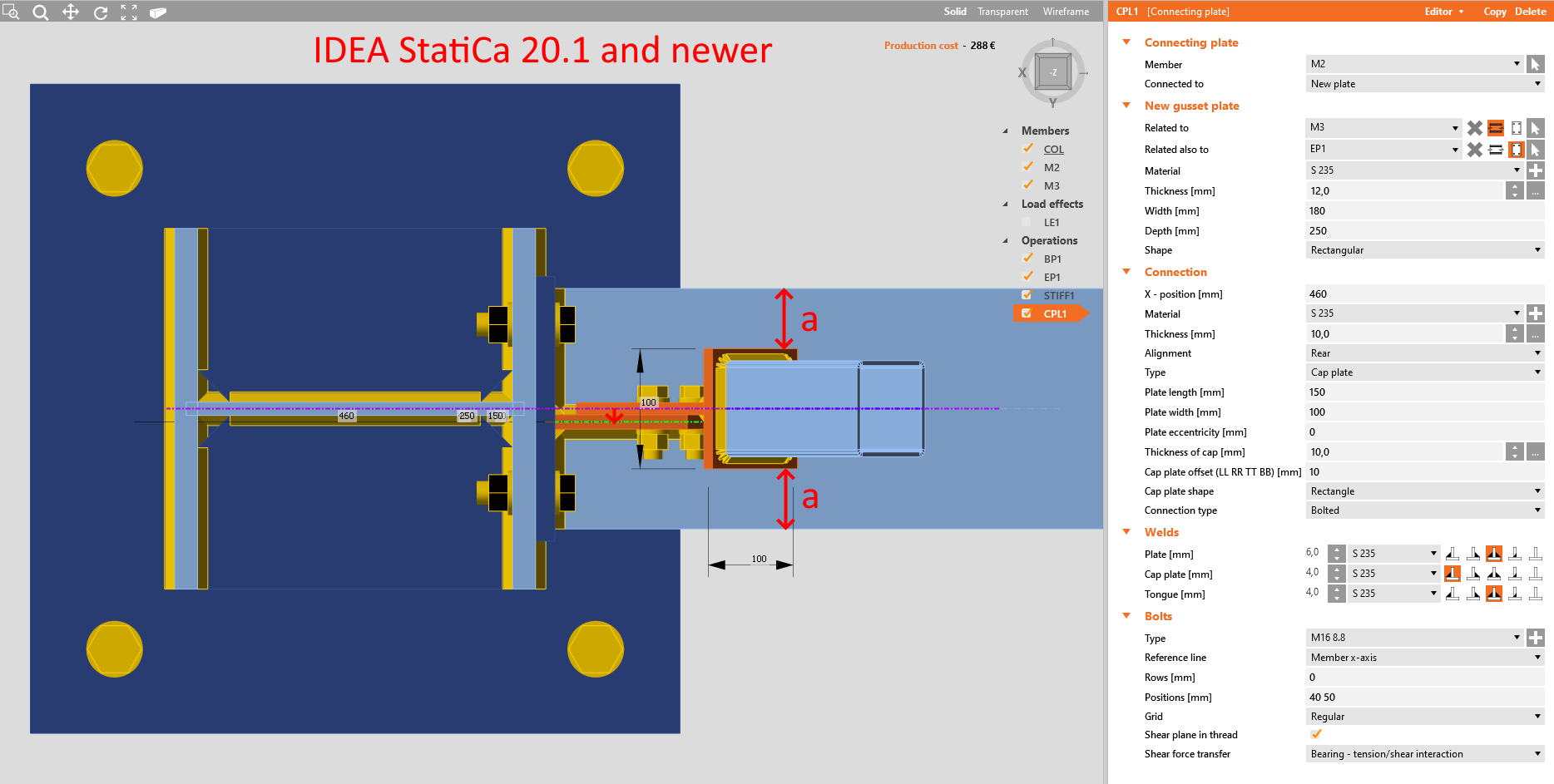
Orice configurație poate fi obținută prin modificarea parametrului Excentricitate placă, precum și a decalajului necesar al elementului diagonal.
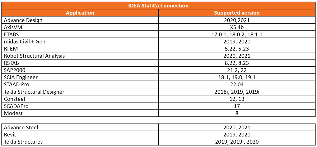
BIM links
Versions of applications supported by IDEA StatiCa 20.1 (Steel)
Selecție în masă pentru software CAD și MEF
Managerul de verificare conform codului (CCM) pentru legăturile BIM a fost îmbunătățit prin posibilitatea de a selecta mai multe noduri ale modelului global dintr-o singură operație. Această funcție este disponibilă atât pentru aplicațiile CAD, cât și pentru cele MEF.
În aplicațiile CAD, veți găsi un buton nou, iar în aplicațiile MEF, această funcție funcționează prin selectarea mai multor noduri în modelul global și selectarea butonului Connection/Member în CCM.
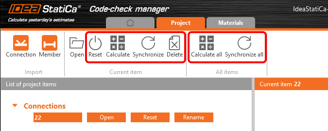
Selecție în masă în software MEF
În software-ul MEF, selectați nodurile individuale unul câte unul sau trageți peste mai multe noduri și selectați-le în masă. Apoi faceți clic pe butonul Connection sau Member din CCM pentru a importa datele.
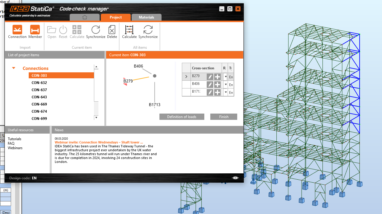
Puteți utiliza, de asemenea, funcția Sincronizare totală după modificarea parametrilor în modelul structural (de ex. combinație de încărcări, secțiunea transversală a unei grinzi) pentru a încărca noile date în toate nodurile din listă, păstrând în același timp proiectul creat anterior.
Selecție în masă în software CAD
Pentru software-ul CAD, există două butoane în CCM - Bulk și One.
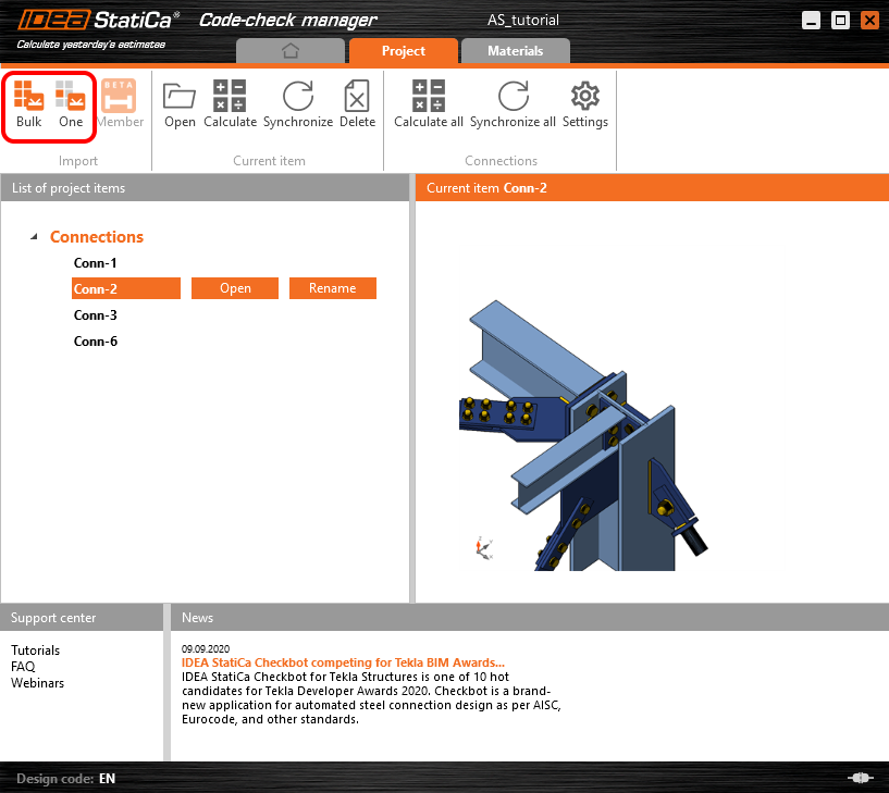
Pentru selecția One trebuie să parcurgeți trei pași - selectați nodul, selectați elementele și selectați componentele îmbinării, apăsând bara de spațiu pentru a confirma fiecare pas.
Pentru selecția Bulk, trageți peste o parte a structurii în modelul CAD și apăsați bara de spațiu.
Elementul portant principal este ales automat folosind algoritmul de selecție (de ex. mai întâi este ales un stâlp). Poziția nodului este aleasă automat în centrul de greutate al secțiunii transversale la capătul elementului portant terminal sau în mijlocul elementului continuu.
În prezent, singura modalitate de a modifica selecția automată este utilizarea selecției One în locul acesteia, caz în care va fi selectat primul element.
Găsiți informații despre limitările legăturilor BIM în articolele conexe de mai jos sau căutați în Centrul de asistență.
Disponibil în ediția Expert și Enhanced .
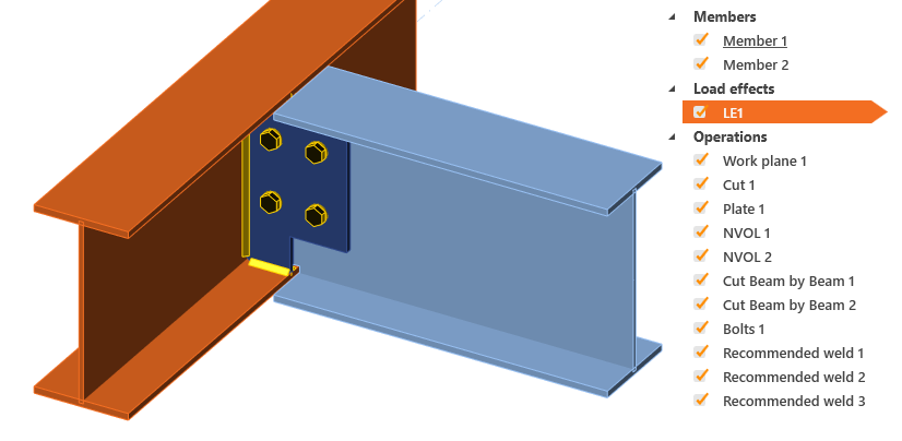
Importul sudurilor recomandate
Când este selectată această opțiune, se efectuează o verificare pentru sudurile potențial lipsă. Aceste suduri sunt apoi adăugate și importate împreună cu restul componentelor.
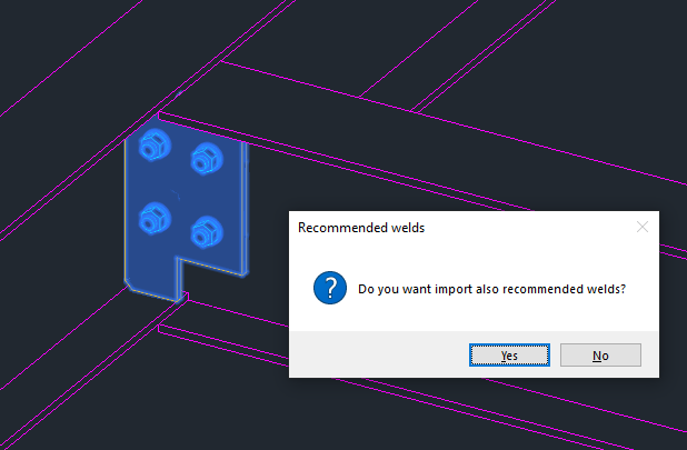
Aceste suduri pot lipsi din cauza unui export incorect sau, eventual, nu se află deloc în modelul CAD. Sudurile adăugate sunt apoi etichetate ca „sudură recomandată" în arborele de operații din IDEA StatiCa Connection.
Disponibil în ediția Expert și Enhanced .
Licensing
Licensing improvements highlights:
- Possibility of the automatic sign out after you close IDEA StatiCa
- IDEA StatiCa launches 40 % faster
- Better error messages so you know what the problem with your license is
- New License dialog with “Forgotten password” button at hand
Alte modificări
Localizări
Am schimbat modul de localizare al aplicațiilor noastre. Prima versiune, IDEA StatiCa 20.1.2515, este lansată doar în engleză și cehă. Vom adăuga alte limbi în următorul patch în curând.
Noul EULA
Odată cu noua lansare a produsului, Acordul de Licență pentru Utilizatorul Final a fost actualizat. Puteți găsi cea mai recentă versiune EULA aici.