
Proiectare automată a șuruburilor
Publicat pentru prima dată în IDEA StatiCa 24.0, acest articol a fost actualizat în versiunea 25.1.
Există două tipuri de proiectare automată a șuruburilor: Proiectare automată și Proiectare automată a șuruburilor. Proiectarea automată se concentrează pe „prima estimare" (geometria inițială), în timp ce Proiectarea automată a șuruburilor rafinează specific dispunerea dispozitivelor de fixare pentru eficiență economică. Noul design este creat pe baza setărilor selectate, care sunt explicate în continuare. Aceste funcționalități acționează ca asistenți puternici pentru accelerarea procesului de inginerie, oferind o propunere de design solidă, gata pentru verificarea finală.
Proiectare automată
Funcția de proiectare automată servește ca instrument rapid de proiectare preliminară. Permite generarea rapidă a unei geometrii valide a îmbinării, pe baza regulilor standard și a proprietăților elementelor conectate.
Funcția Proiectare automată este pregătită pentru următoarele operații: Placă de capăt, Placă la placă, Eclisat și Placă de inimă/Placă de forfecare.
Proiectarea automată poate fi apelată prin una dintre următoarele metode:
- Proiectare automată prin clic dreapta pe operația listată mai sus cu șuruburi. Aici, veți proiecta automat nu doar șuruburile, ci și sudurile.
- Clic dreapta pe Operație în arbore în scena 3D și selectarea Proiectare automată totală. Aici, veți proiecta automat nu doar șuruburile, ci și sudurile.
- Proiectare automată în partea de sus a proprietăților operației din dreapta

Pentru operațiile Placă de capăt și Placă la placă, sunt disponibile setări suplimentare de proiectare automată:
- Forfecare: Proiectează placa și șuruburile pentru transferul forței de forfecare (doar pentru operația Placă de capăt).
- Afluent: Proiectează placa la nivelul tălpilor superioare și inferioare ale grinzii.
- Extins: Proiectează placa să se extindă dincolo de tălpile superioare și inferioare ale grinzii.


Procesul de proiectare automată este determinat de proprietățile elementelor de calcul și de setările globale specifice. Algoritmul evaluează următoarele date de intrare:
- Secțiune transversală & Material: Parametrii geometrici și de material ai grinzii/stâlpului conectat.
- Setarea rezistenței grinzii: Utilizează procentul definit în Setări proiect > Calcul – General (implicit 40%) pentru a proiecta îmbinarea pe baza capacității secțiunii transversale. Aplică rezistența la forfecare pe inimi și rezistența la încovoiere pe tălpi.
- Reguli de alcătuire constructivă: Respectă regulile de distanțe și distanțe față de margine situate în aceleași setări.
- Numărul maxim de rânduri de șuruburi pe placa de inimă: Respectă limita maximă a rândurilor de șuruburi definită în aceleași setări (implicit 2).

Când rulați Proiectarea automată, funcția va calcula și ajusta automat următorii parametri ai operației de fabricație pentru a găsi un design funcțional:
- Proprietăți placă: Grosime, dimensiuni (lățime/înălțime) și decalaj
- Proprietăți șuruburi: Numărul total de șuruburi și pozițiile lor specifice
Funcția menține următorii parametri nemodificați:
- Diametrul și clasa șuruburilor
- Clasa materialului plăcilor
Recomandare: Pentru o propunere sofisticată care ia în considerare economia, eficiența și distribuția optimă, utilizați funcționalitatea Proiectare automată a șuruburilor. Rețineți că această funcție este concepută specific pentru Placa de inimă și Eclisat și este limitată la îmbinările în care șuruburile sunt supuse exclusiv forțelor de forfecare.
Proiectare automată a șuruburilor
Funcția Proiectare automată a șuruburilor este alimentată de învățare automată, integrată cu formule analitice bazate pe standardele de calcul. Această abordare permite instrumentului să propună o soluție care echilibrează eficiența structurală cu economia, rezultând o distribuție optimă a șuruburilor.
Funcția Proiectare automată a șuruburilor este pregătită pentru următoarele operații: Placă de inimă și Eclisat, unde șuruburile sunt încărcate predominant la forfecare.
Proiectarea automată a șuruburilor poate fi apelată doar după calcul prin:
- Clic dreapta pe operația listată mai sus cu șuruburi

Algoritmul se bazează pe forțele interioare aplicate (N, Vz, My)—luând în considerare în mod specific forțele de forfecare rezultante în șuruburi—și le evaluează în raport cu următoarele setări globale:
- Reguli de rotunjire: Poziționarea șuruburilor este ajustată conform setărilor de rotunjire din Proiect > Preferințe > Unități aplicație - Rotunjire entitate nouă.
- Șuruburi: Grad de utilizare țintă: Această limită este definită în Setări proiect > Calcul – General > Proiectare automată (valoarea implicită este 0,9). Algoritmul compară încărcările reale cu această valoare setată pentru a găsi o soluție care respectă cerința. Valoarea specifică verificată este Gradul de utilizare la forfecare (Uts).
- Reguli de alcătuire constructivă: Algoritmul respectă regulile de distanțe și distanțe față de margine situate în Setări proiect > Calcul – General > Alcătuire constructivă șuruburi.

Când rulați Proiectarea automată a șuruburilor, funcția va calcula și ajusta automat următorii parametri ai operației Placă de inimă sau Eclisat pentru a găsi un design optimizat:
- Proprietăți șuruburi: Numărul total de șuruburi și geometria grilei de șuruburi
- Proprietăți placă: Dimensiuni (ajustate conform noii grile de șuruburi) și grosime (ajustată parțial pentru a obține aceeași rezistență la presiune pe gaură ca elementul conectat)
Funcția menține următorii parametri nemodificați:
- Diametrul și clasa șuruburilor
- Clasa materialului plăcilor
Ipoteze de bază
- Algoritmul Proiectare automată a șuruburilor ia în considerare doar forțele și momentele în planul plăcii (N, Vz, My - generând doar forțe de forfecare pentru șuruburi) din efectele de încărcare aplicate în model. Orice forțe de întindere apărute în șuruburi (generate de alte încărcări sau de efectul de pârghie) nu sunt luate în considerare în procesul de proiectare automată.
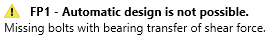
- Dacă gradul de utilizare la întindere este ridicat (mai mult de 30% din gradul de utilizare total), Proiectarea automată a șuruburilor poate da rezultate imprecise, iar utilizatorul poate primi un mesaj de avertizare. Proiectarea automată a șuruburilor este furnizată, dar rezultatele pot fi influențate semnificativ de forța de întindere din șuruburi.

- Șuruburile din operații trebuie setate cu tipul de forță de forfecare presiune pe gaură/interacțiune la forfecare. Proiectarea automată a șuruburilor nu se efectuează dacă șuruburile sunt setate ca frecare, iar utilizatorul primește un mesaj de avertizare.
- Forțele din șuruburi nu sunt calculate corect când modelul este supraîncărcat și analiza se finalizează cu deformații plastice semnificative. Prin urmare, Proiectarea automată a șuruburilor lucrează cu forțe incorecte în șuruburi și nu poate furniza niciun rezultat corect.
- Proiectarea automată nu suportă secțiuni transversale tubulare.
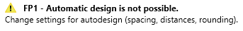
- Dacă secțiunea transversală selectată nu este adecvată pentru plasarea grilei de șuruburi conform cerințelor geometrice, puteți primi de asemenea o avertizare. De exemplu, în cazurile cu tălpi înguste, este imposibil să se respecte cerințele privind distanțele față de margine, distanțele față de perete etc.
- Proiectarea automată și proiectarea automată a șuruburilor reprezintă un alt instrument care ajută la accelerarea procesului de proiectare și la simplificarea și automatizarea acestuia, menținând în același timp siguranța și eficiența economică. Alături de dimensionarea sudurilor, funcționalitatea reprezintă următorul pas în procesul automatizat de proiectare a îmbinărilor.
Aceasta aduce simplificarea procesului iterativ de găsire a proiectului adecvat al îmbinărilor. Proiectarea automată a șuruburilor la forfecare ia în considerare încărcările active pe îmbinările simple. În loc de un proces iterativ, utilizatorul apelează pur și simplu această funcție de proiectare automată, iar aplicația găsește proiectul adecvat.