Legătură BIM Midas Civil pentru evaluarea capacității portante a podurilor
Vom prezenta procedura pe un model simplu al unui pod cu o singură grindă pretensionată cu trei deschideri. Am pregătit un fișier zip pentru descărcare care conține toate fișierele necesare pentru a finaliza acest tutorial. Este disponibil aici. Vă rugăm să descărcați acest fișier și să îl dezarhivați într-o locație la alegere.
1 Import
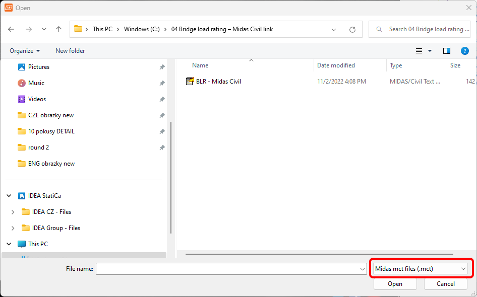
Porniți aplicația IDEA StatiCa, selectați Import din alte programe din fila BIM, și selectați fișierul .mct pregătit. Un model sursă în Midas Civil este disponibil și în fișierele de descărcare.

Dacă importați pentru prima dată, configurați generarea grupurilor de calcul și a elementelor de calcul. Programul unește automat suprastructura podului importat într-un singur element de calcul. Această setare poate fi salvată și nu va mai fi afișată data viitoare.

Dacă programul descoperă probleme în timpul importului, acestea vor fi afișate în fereastra Detalii import. În cazul nostru, este vorba despre un material cu densitate zero utilizat pentru calculul greutății proprii a grinzilor transversale.

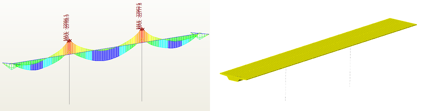
Modelul importat ar trebui să arate astfel în scena 3D.

După import, trebuie să setați parametrii de calcul în fila Date proiect. Primul dintre aceștia este Codul și Anexa națională, apoi Tipul de pod și, în final, activați funcționalitatea Evaluarea capacității portante a podului.

Programul vă va afișa un mesaj de avertizare, sugerând că ar fi util să verificați setările grupului după efectuarea acestei modificări. Pentru importul corect al forțelor interne din programul Midas Civil, este necesar să se distingă corect cazurile de încărcare permanentă, încărcările de trafic și alte încărcări variabile în Midas Civil.
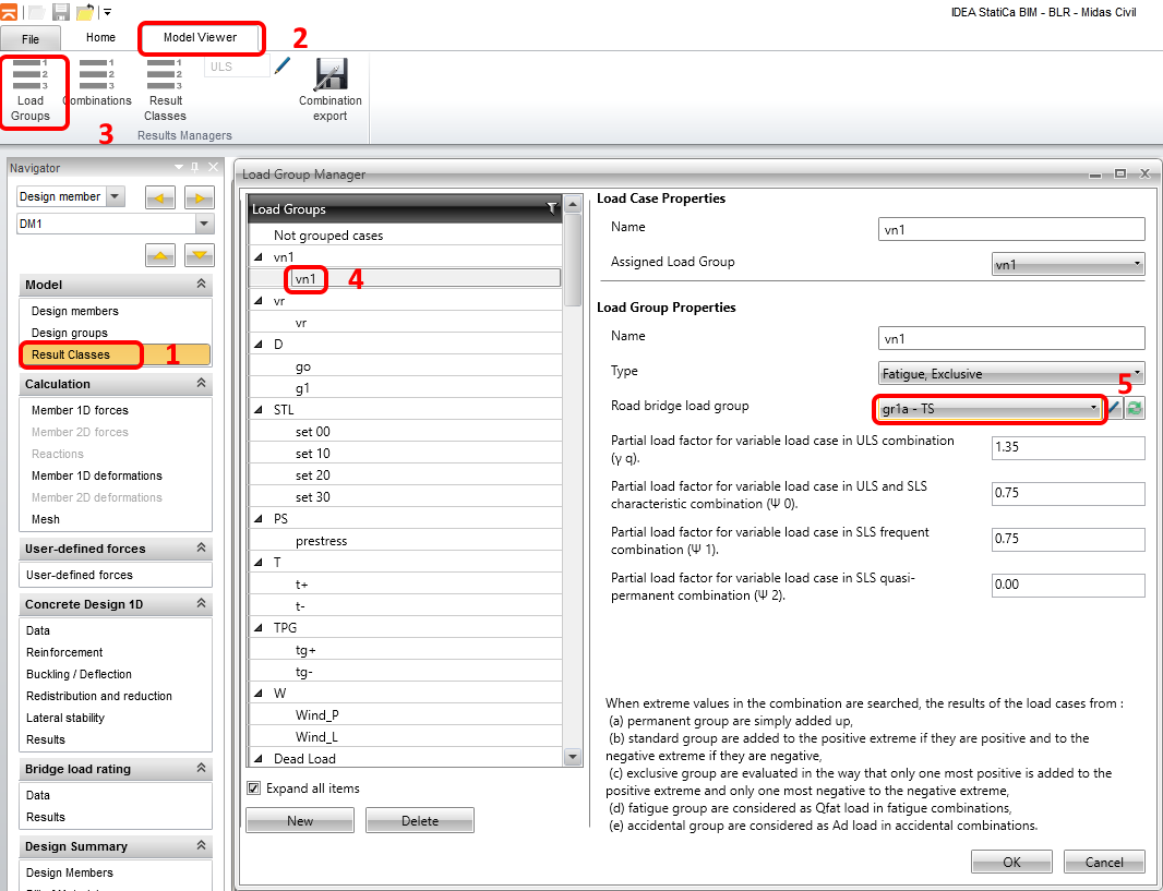
În pasul următor, verificați și setați grupurile de încărcare ale cazurilor de încărcare. Începeți cu grupul de încărcare vn1, care este o încărcare vehiculară conform codului pentru determinarea capacității portante normale a podului. Este important să se distingă această condiție de încărcare ca încărcare de trafic, deoarece prin căutarea iterativă a mai multor cazuri de încărcare de trafic definite, programul calculează capacitatea portantă.
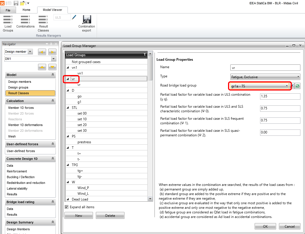
În mod similar, continuați cu grupul de încărcare vr, care este vehiculul standard cu șase osii pentru determinarea capacității portante de rezervă.
Continuați verificând setările pentru grupurile de încărcare g0 (greutate proprie) și g1 (greutate proprie a elementelor secundare), precum și pentru încărcările de pretensionare.

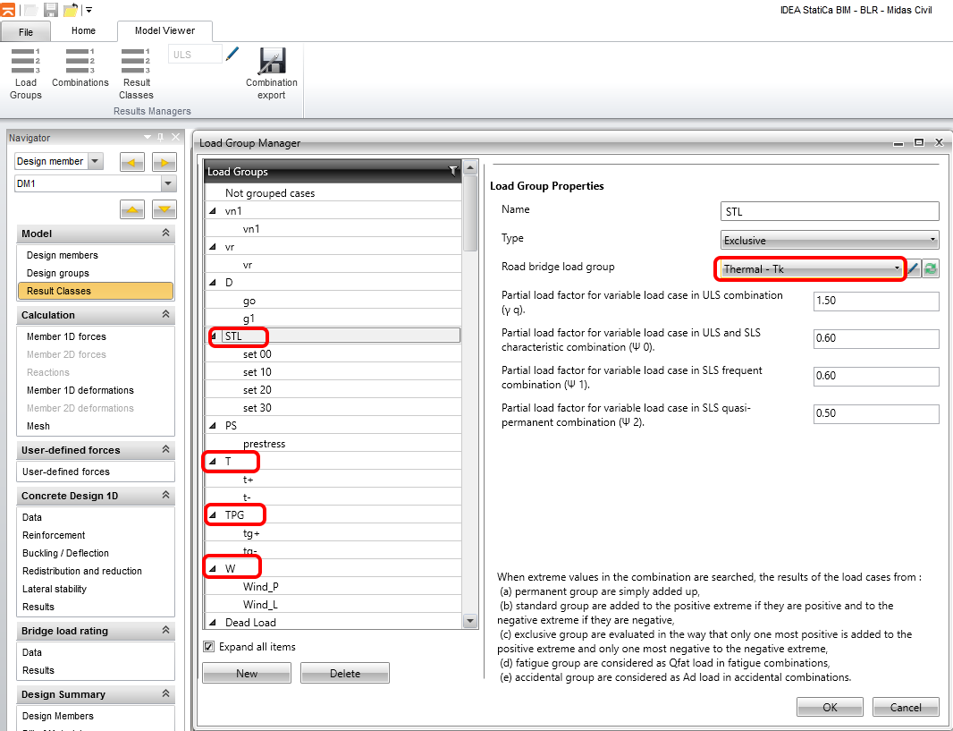
Pentru grupurile de încărcare de tasare, temperatură și vânt, setați tipul grupului de încărcare Termică - Tk. Aceasta este modalitatea prin care le distingeți de încărcările de trafic și de încărcările permanente. Programul ignoră valorile coeficienților de încărcare și ale coeficienților de combinare pentru cazurile individuale de încărcare, deoarece acestea au fost preluate din setările combinațiilor de încărcare din programul Midas Civil.
În pasul următor, verificați dacă forțele interne au fost importate corect prin compararea anvelopei momentelor încovoietoare din combinația ULS _6.10_vn1. Puteți seta Scara 15.5 pentru o vizualizare mai bună.


2 Definirea armăturii
Pasul următor este definirea armăturii și setarea secțiunilor pentru verificare. Mai întâi, împărțiți suprastructura în cinci zone de armătură după cum se arată în figură și începeți definirea lungimii de la ultima zonă.

Pentru întreaga structură, vom avea 2 tipuri de armătură, pentru momentul încovoietor negativ și pozitiv. Puteți adăuga sau edita armătura prin butoanele prezentate în imaginea următoare. Tipul A-A pentru zonele cu moment încovoietor pozitiv și B-B pentru cele cu moment încovoietor negativ. Pozițiile de verificare le vom seta ulterior.

Vom utiliza șabloane de armătură pregătite pentru ambele tipuri. Deschideți editorul de armătură, rulați dialogul Introducere armătură și găsiți fișierul re A-A.nav în folderul proiectului.

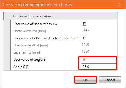
În fila setări utilizator, introduceți valoarea definită de utilizator a unghiului diagonalelor la 35° și faceți clic pe OK. Închideți editorul de armătură pentru a finaliza setarea tipurilor A-A. În mod similar, utilizați șablonul de armătură pentru tipul B-B.
3 Setarea calculului de evaluare a capacității portante
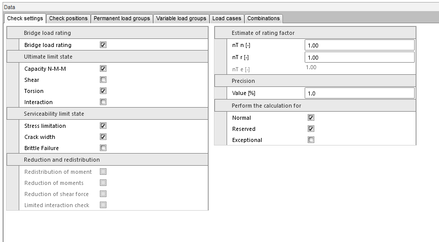
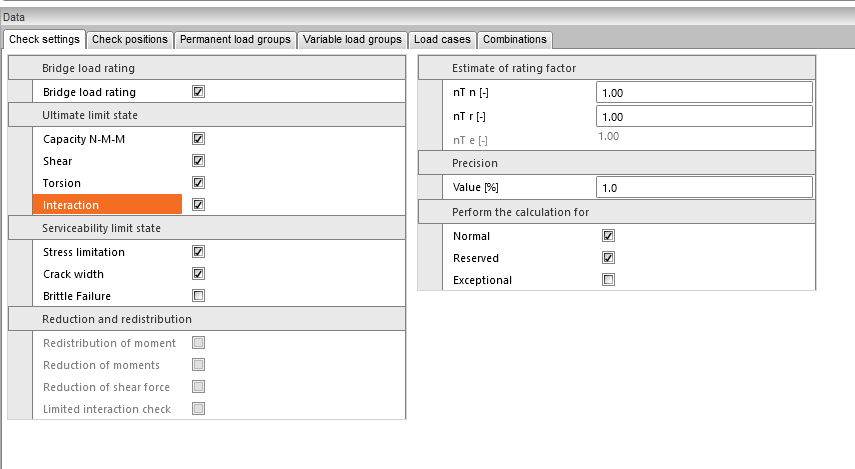
Pentru a seta calculul de evaluare a capacității portante, comutați la fila Date din secțiunea Evaluarea capacității portante a podului. Fila Setări verificare definește verificările care urmează să fie efectuate; vom reveni la aceste setări ulterior.
Factorul estimat de evaluare a capacității portante poate fi setat dacă doriți să accelerați calculul și, nu în ultimul rând, se setează tipul de evaluare a capacității portante care va fi calculat. În cazul nostru, cazurile de încărcare de trafic normal și de rezervă sunt definite în modelul sursă MIDAS. Astfel, veți seta doar Normal și Rezervă pentru calcul.

Mai întâi, vom efectua analiza de evaluare a capacității portante în Sec 1 - reazem 2. Vom lua în considerare verificările pentru încovoiere și torsiune.
Ulterior, analiza se efectuează la o distanță de 1,5 m față de reazem, incluzând considerarea forfecării și a interacțiunii M-V-T (moment-forfecare-torsiune).
Pe a doua filă, setați Pozițiile de verificare pentru verificările secțiunilor individuale.

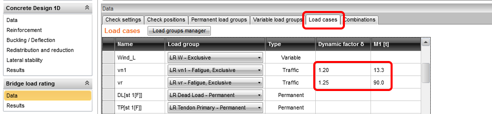
În fila Caz de încărcare, setați coeficienții dinamici și greutatea unui vehicul corespunzătoare greutății vehiculului din modelul 3D MEF din programul Midas pentru efectele variabile de trafic.
Fila Combinații este utilizată pentru generarea și setarea combinațiilor pentru tipurile individuale de evaluare a capacității portante (normal, rezervă și excepțional).
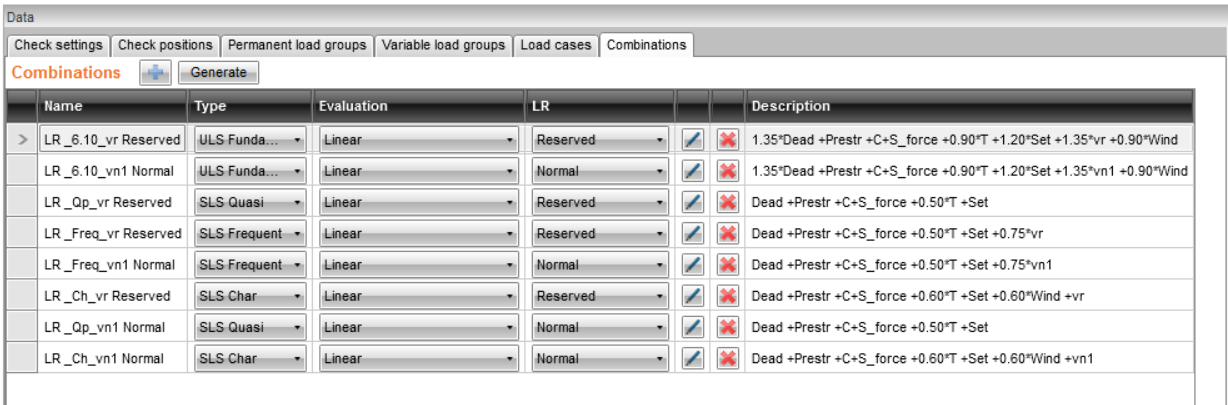
După apăsarea butonului Generare, combinațiile vor fi generate automat. Vom revizui și reduce numărul acestora în pasul următor, deoarece unele sunt redundante. De exemplu, pe prima linie există o combinație LR_6.10_vr Normal, în care încărcarea de trafic vr (rezervă) este utilizată pentru calculul capacității portante normale. Această combinație nu are sens, deci ștergeți-o împreună cu celelalte combinații redundante.

Lista finală a combinațiilor de încărcare ar trebui să arate astfel:
4 Calculul de evaluare a capacității portante
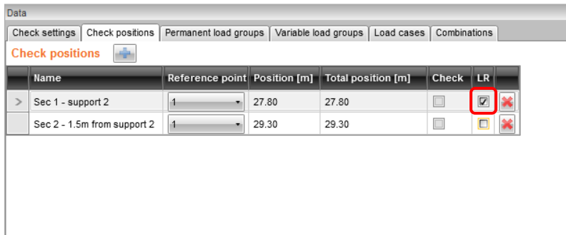
Comutați din nou la fila Poziție de verificare și bifați caseta LR pentru Secțiunea 1. Aceasta definește faptul că calculul capacității portante va fi efectuat doar pentru secțiunea 1 (care este reazemul).
Apoi reveniți la fila Setări verificare și efectuați setările.
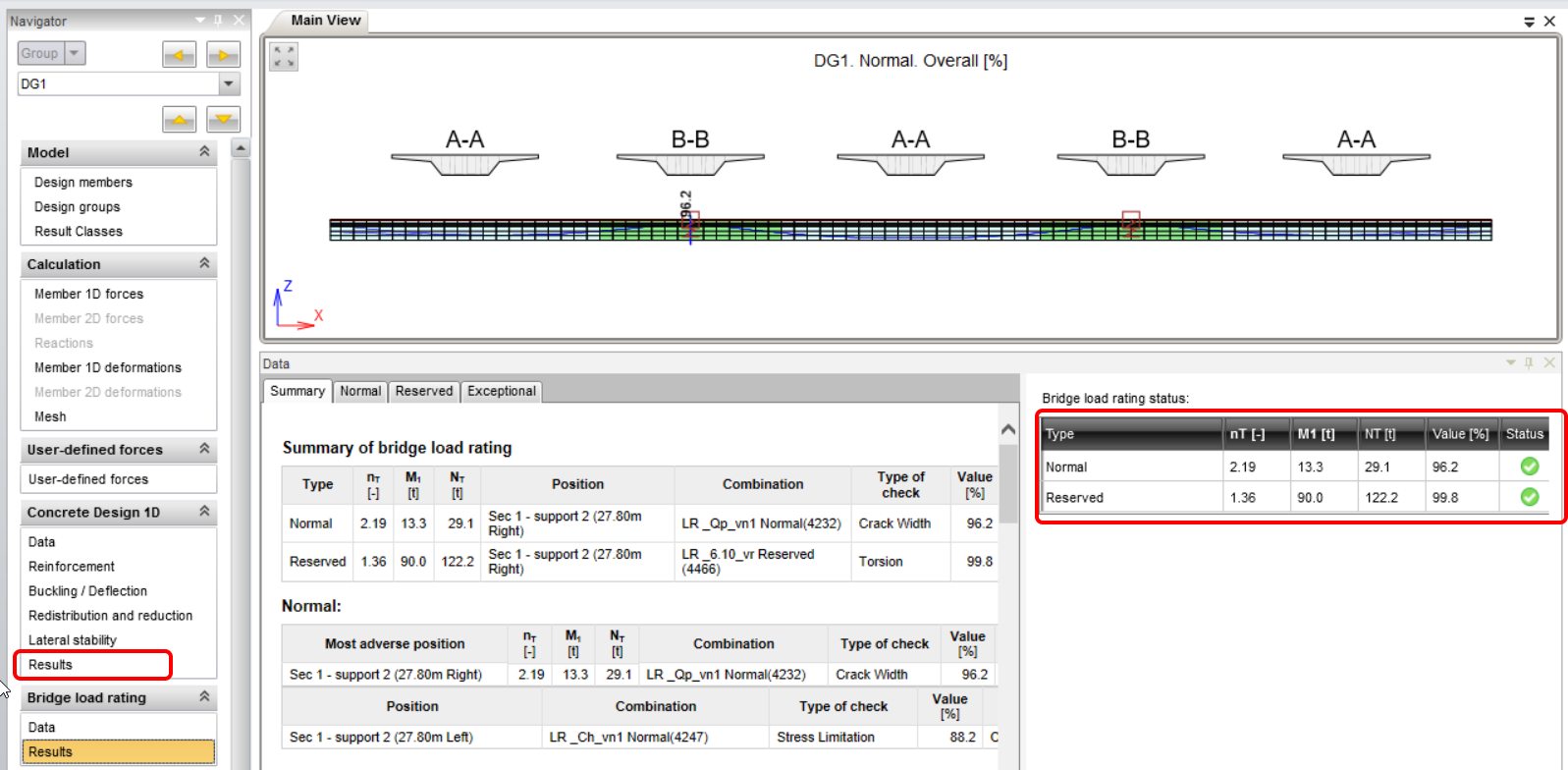
Comutați la fila Rezultate. Aceasta va porni automat calculul, în care programul caută iterativ un multiplu al încărcării de trafic specificate, la care una dintre verificări va atinge valoarea de 100%. După finalizarea iterației, puteți vizualiza valorile rezultante ale capacității portante și multiplii de încărcare în partea dreaptă a ecranului. Pe partea stângă a acestui câmp, verificarea critică care a determinat capacitatea portantă este evidențiată.
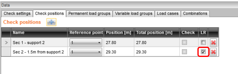
Acum efectuați verificarea secțiunii 2, incluzând considerarea interacțiunii M-V-T (moment-forfecare-torsiune). Comutați la fila Poziții de verificare și bifați caseta LR pentru secțiunea 2.
Apoi comutați la fila Setări verificare și actualizați setările.
Comutați la fila Rezultate pentru a porni din nou calculul.

Făcând clic pe butonul Detaliat din bara de instrumente superioară, veți comuta la programul RCS, unde puteți vizualiza verificările detaliate ale stărilor limită individuale.
5 Raport
În ultimul pas, accesați fila Raport, câmpul Detaliat. IDEA StatiCa oferă un raport complet editabil pe care îl puteți tipări sau exporta în diverse formate, inclusiv pdf.

