Cum se creează o vedere în secțiune
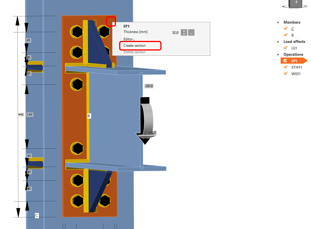
Pentru a crea o vedere în secțiune, faceți clic dreapta pe orice placă din modelul 3D al nodului și selectați Create section. Imediat, vederea în secțiune este creată.
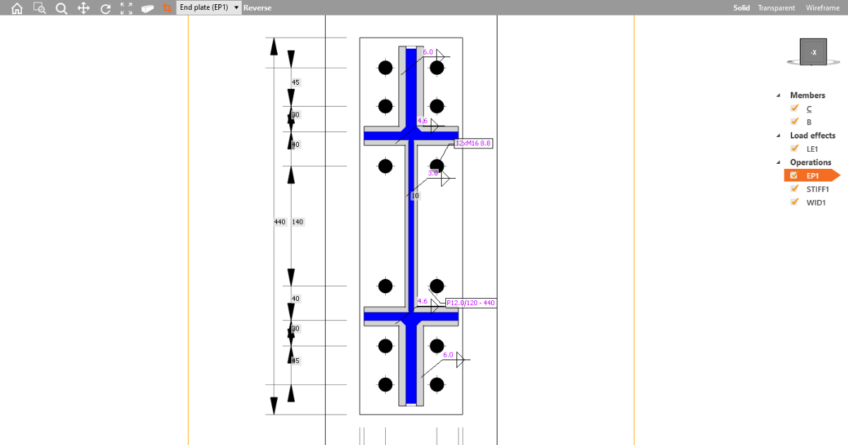
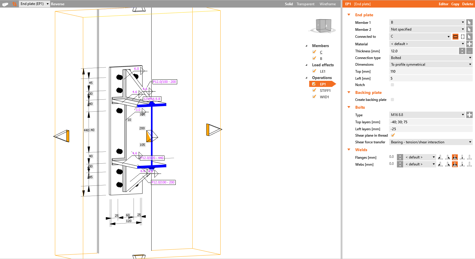
Dacă doriți să modificați dimensiunea secțiunii în sine, faceți clic pe marginea galbenă a secțiunii și trageți săgețile.
Pentru a șterge o vedere în secțiune, faceți clic dreapta pe aceeași placă pentru care ați creat anterior vederea în secțiune și selectați Delete section.
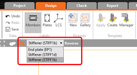
Pot fi definite mai multe vederi în secțiune pentru diferite plăci ale nodului. Pentru a comuta între secțiunile create, selectați-o pe cea dorită din lista derulantă.
Direcția secțiunii poate fi modificată prin comanda Reverse. Vederea modelului în secțiune poate fi activată/dezactivată prin butonul de secțiune plasat în partea stângă a listei derulante cu elementele de secțiune.
Vederile în secțiune pot fi adăugate în Raport ca imagini din galerie (inclusiv cu dimensiunile) sau automat după selectarea butonului de comandă pentru secțiuni în configurarea raportului detaliat.
Lista de materiale va include automat toate secțiunile definite.
Vizionați videoclipul despre cum să lucrați cu ușurință cu secțiunile: