Verificarea conform codului a ancorelor (EN)
Următoarele tipuri de buloane de ancoraj sunt disponibile:
- Ancore post-instalate:
- Drepte
- Turnate în cofraj:
- Placă tip șaibă - Circulară
- Placă tip șaibă - Dreptunghiulară
- Dorn cu cap
- Cârlig
- Armătură
Rezistențele oțelului sunt determinate conform EN 1993-1-8, EN 1992-4 sau EN 1992-1-1.
Rezistențele betonului sunt determinate conform EN 1992-4.
În cazul dispozitivelor de fixare post-instalate (drepte), cedarea prin smulgere, cedarea combinată prin smulgere și cedarea betonului pentru ancorele lipite, precum și cedarea prin despicarea betonului nu sunt verificate din cauza lipsei informațiilor disponibile doar pentru tipul specific de ancoră și adeziv de la producătorul de ancore.
În Setările proiectului, sunt disponibile opțiuni pentru activarea/dezactivarea verificărilor la smulgerea conului de beton la întindere și forfecare. Dacă verificarea la smulgerea conului de beton nu este activată, se presupune că armătura dedicată este proiectată să preia forța. Mărimea forței este furnizată în formule. Utilizatorul poate folosi link-ul către aplicația Detail pentru a efectua verificările elementelor din beton armat.
De asemenea, betonul poate fi setat ca fisurat sau nefisurat. Betonul nefisurat trebuie să fie în compresiune permanentă care împiedică fisurile de contracție. Rezistențele betonului nefisurat sunt mai mari.
Informație:
Eurocodul în forma sa actuală nu oferă un răspuns clar și neambiguu cu privire la momentul în care ancorele turnate în cofraj trebuie proiectate conform EN 1993-1-8 sau EN 1992-4. Un ghid util îl reprezintă modul de cedare determinant. Dacă modul de cedare dominant este ruperea prin întindere a ancorului de oțel, trebuie aplicat EN 1993-1-8. Aceasta privește în mod tipic ancorele cu lungime de ancoraj suficientă, cum ar fi buloanele de ancoraj. Invers, acolo unde alte moduri de cedare sunt determinante (de ex. cedări legate de beton), trebuie utilizat EN 1992-4. Aceasta se aplică în principal dispozitivelor de fixare.
În IDEA StatiCa:
- Ancorele turnate în cofraj cu plăci tip șaibă și ancorele cu cârlig sunt proiectate conform EN 1993-1-8.
- Celelalte tipuri de ancore sunt proiectate conform EN 1992-4 / EN 1992-1-1.
Unele țări abordează această ambiguitate prin prevederi naționale (de ex. Olanda), în concordanță cu abordarea adoptată în IDEA StatiCa. Motivul îl reprezintă diferența dintre datele de publicare ale standardelor:
EN 1993-1-8 (2005) vs. EN 1992-4 (2018).
Noua generație de Eurocodeuri adoptă o abordare mai clară și mai bine explicată față de această problemă.
Rezistența la întindere a oțelului (EN 1993-1-8, Tabelul 3.4)
Ancorele cu placă tip șaibă sau cârlig sunt verificate conform codului de proiectare a oțelului.
\[ F_{t,Rd} = \frac{c \cdot k_2 \cdot f_{ub} \cdot A_s}{\gamma_{M2}} \]
unde:
- c – reducerea rezistenței la întindere a buloanelor cu filet tăiat conform EN 1993-1-8 – Cl. 3.6.1. (3), editabil în Setările proiectului
- k2 = 0,9 – factor pentru ancorele fără cap înecat
- fub – rezistența ultimă la întindere a bulonului de ancoraj
- As – aria secțiunii transversale efective a bulonului de ancoraj
- \(\gamma_{M2}=1.25\) – factor parțial de siguranță pentru buloane (EN 1993-1-8, Tabelul 2.1), editabil în Setările proiectului
Rezistența la întindere a oțelului (EN 1992-4, Cl. 7.2.1.3)
Dispozitivele de fixare post-instalate și dornurile cu cap sunt verificate conform codului de proiectare a betonului EN 1992-4
\[ N_{Rd,s} = \frac{N_{Rk,s}}{\gamma_{Ms}} \]
unde:
- NRk,s = c ∙ As ∙ fuk – rezistența caracteristică a unui dispozitiv de fixare în cazul cedării oțelului
- c – reducerea rezistenței la întindere a buloanelor cu filet tăiat conform EN 1993-1-8 – Cl. 3.6.1. (3), editabil în Configurarea codului
- As – aria secțiunii transversale efective a bulonului de ancoraj
- fuk – rezistența ultimă caracteristică la întindere a bulonului de ancoraj
- \(\gamma_{Ms}=1.2 \cdot \frac{f_{uk}}{f_{yk}} \ge 1.4\) – factor parțial de siguranță pentru cedarea oțelului la întindere (EN 1992-4, Tabelul 4.1)
- fyk – rezistența caracteristică la curgere a bulonului de ancoraj
Rezistența la întindere a oțelului (EN 1992-1-1, Cl. 3.3.6)
Armătura sudată de placa de bază se află în afara domeniului de aplicare al EN 1992-4, iar regulile din EN 1992-1-1 se aplică. Acest cod nu furnizează nicio formulă specifică, ci mai degrabă o diagramă efort-deformație și aria secțiunii transversale care trebuie utilizate în calculele de proiectare conform Cl. 3.3.6. Datorită utilizării sudurii, care introduce incertitudini suplimentare, se utilizează un factor parțial de siguranță mai conservativ, \(\gamma_{M2}\).
\[F_{t,Rd} = A_s \cdot f_{ud} \]
unde:
- \(A_s\) – aria secțiunii transversale efective
- \(f_{ud}=\frac{k \cdot f_{yk}}{\gamma_{M2}}\) – rezistența de calcul la întindere a armăturii
- \(k\) – factor de ductilitate
- \(f_{yk}\) – rezistența caracteristică la curgere a armăturii
- \(\gamma_{M2}\) – factor parțial de siguranță pentru buloane, suduri sau rupere prin întindere, editabil în Setările proiectului
Rezistența la smulgerea conului de beton a unei ancore sau a unui grup de ancore (EN 1992-4, Cl. 7.2.1.4):
\[ N_{Rd,c} = \frac{N_{Rk,c}}{\gamma_{Mc}} \]
unde:
- \(N_{Rk,c}=N_{Rk,c}^0 \cdot \frac{A_{c,N}}{A_{c,N}^0} \cdot \psi_{s,N} \cdot \psi_{re,N} \cdot \psi_{ec,N} \cdot \psi_{M,N}\) – rezistența caracteristică a unui dispozitiv de fixare, a unui grup de dispozitive de fixare și a dispozitivelor de fixare întinse dintr-un grup în cazul smulgerii conului de beton
- \(N_{Rk,c}^0 = k_1 \sqrt{f_{ck}} h_{ef}^{1.5}\) – rezistența caracteristică a unui singur dispozitiv de fixare plasat în beton și neinfluențat de dispozitivele de fixare adiacente sau de marginile elementului de beton
- k1 – factor care ține seama de condiția betonului și tipul de ancoră; pentru ancorele cu cap turnate în cofraj (cu plăci tip șaibă) k1 = 8,9 pentru beton fisurat și k1 = 12,7 pentru beton nefisurat; pentru dispozitivele de fixare post-instalate (ancore drepte) k1 = 7,7 pentru beton fisurat și k1 = 11,0 pentru beton nefisurat
- fck – rezistența caracteristică la compresiune pe cilindru a betonului
- hef – adâncimea de încastrare a ancorului în beton; pentru trei sau mai multe margini apropiate, se aplică EN 1992-4, Cl. 7.2.1.4 (8) și se utilizează în formule \(h'_{ef} = \max \left \{ \frac{c_{max}}{c_{cr,N}} \cdot h_{ef}, \, \frac{s_{max}}{s_{cr,N}} \cdot h_{ef} \right \}\) efectiv în locul valorii inițiale pentru NRk,c0, ccr,N, scr,N, Ac,N, Ac,N0, ψs,N și ψec,N
- Ac,N – aria proiectată reală, limitată de suprapunerea conurilor de beton ale dispozitivelor de fixare adiacente, precum și de marginile elementului de beton
- Ac,N0 = scr,N2 – aria proiectată de referință, adică aria de beton a unei ancore individuale cu distanță mare între ancore și față de margine la suprafața betonului
- \(\psi_{s,N}=0.7+0.3 \cdot \frac{c}{c_{cr,N}} \le 1\) – factor care ține seama de perturbarea distribuției tensiunilor în beton datorită proximității unei margini a elementului de beton
- c – cea mai mică distanță față de margine
- ccr,N = 1,5 ∙ hef – distanța caracteristică față de margine pentru asigurarea transmiterii rezistenței caracteristice a unei ancore în cazul smulgerii conului de beton la încărcare de întindere
- \(\psi_{re,N}=0.5+\frac{h_{ef}}{200} \le 1\) – factor de exfoliere a stratului de acoperire
- \(\psi_{ec,N}=\frac{1}{1+2 \cdot (e_N / s_{cr,N})} \le 1\) – factor care ține seama de efectul de grup atunci când forțe de întindere diferite acționează asupra dispozitivelor de fixare individuale dintr-un grup; ψec,N se determină separat pentru fiecare direcție și se utilizează produsul ambilor factori
- eN – excentricitatea forței de întindere rezultante a dispozitivelor de fixare întinse față de centrul de greutate al dispozitivelor de fixare întinse
- scr,N = 2 ∙ ccr,N – distanța caracteristică dintre ancore pentru asigurarea rezistenței caracteristice a ancorelor în cazul smulgerii conului de beton la încărcare de întindere
- \(\psi_{M,N} = 2- \frac{z}{1.5 \cdot h_{ef}} \ge 1\) – factor care ține seama de efectul unei forțe de compresiune între dispozitivul de fixare și beton în cazul momentelor încovoietoare cu sau fără forță axială; acest parametru este egal cu 1 dacă c < 1,5 hef sau raportul dintre forța de compresiune (inclusiv compresiunea datorată încovoierii) și suma forțelor de întindere din ancore este mai mic de 0,8 sau z / hef ≥ 1,5
- z – brațul de pârghie interior al unui dispozitiv de fixare
- γMc = γc ∙ γinst – factor parțial de siguranță (EN 1992-4, Tabelul 4.1)
- γc – factor parțial de siguranță pentru beton (editabil în Configurarea codului)
- γinst – factor parțial de siguranță care ține seama de siguranța instalării unui sistem de ancoraj (editabil în Configurarea codului)
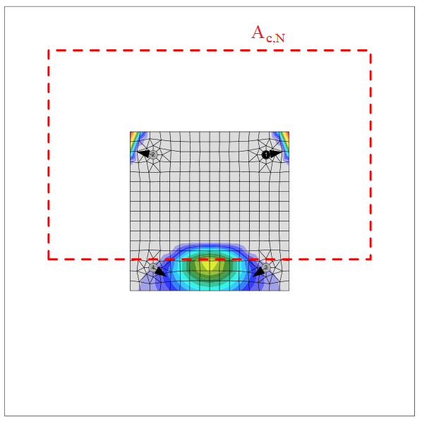
Aria conului de smulgere a betonului pentru un grup de ancore încărcate la întindere care formează un con comun de beton, Ac,N, este indicată prin linia roșie întreruptă.
Rezistența la smulgere (EN 1992-4, Cl. 7.2.1.5)
Rezistența la smulgere este verificată pentru ancorele turnate în cofraj cu plăci tip șaibă și dornuri cu cap conform EN 1992-4, Cl. 7.2.1.5:
\[ N_{Rd,p}=\frac{N_{Rk,p}}{\gamma_{Mc}} \]
unde:
- NRk,p = k2 ∙ Ah ∙ fck – rezistența caracteristică în cazul cedării prin smulgere
- k2 – coeficient dependent de condiția betonului, k2 = 7,5 pentru beton fisurat, k2 = 10,5 pentru beton nefisurat
- Ah – aria de reazem a capului ancorului; pentru placă tip șaibă circulară \(A_h = \frac{\pi}{4} \left ( d_h^2 - d^2 \right )\), pentru placă tip șaibă dreptunghiulară \(A_h = a_{wp}^2 - \frac{\pi}{4} d^2\)
- dh ≤ 6 th + d – diametrul capului dispozitivului de fixare
- th – grosimea capului dispozitivului de fixare cu cap
- d – diametrul tijei dispozitivului de fixare
- fck – rezistența caracteristică la compresiune pe cilindru a betonului
- γMc = γc ∙ γinst – factor parțial de siguranță (EN 1992-4, Tabelul 4.1)
- γc – factor parțial de siguranță pentru beton (editabil în Configurarea codului)
- γinst – factor parțial de siguranță care ține seama de siguranța instalării unui sistem de ancoraj (editabil în Configurarea codului)
Rezistența la smulgere (EN 1992-1-1, Cl. 8.4.4)
Rezistența la smulgere este verificată pentru ancorele turnate în cofraj cu cârlig conform EN 1992-1-1, Cl. 8.4.4. Se presupun bare netede care necesită o lungime de ancoraj dublă față de armătura nervurată (Tabelul 3.26 din BS 8110-1).
\[N_{Rd,p}=A_a \cdot f_{ya} \cdot \frac{l_b}{l_{bd}}\]
unde:
- Aa – aria secțiunii transversale efective a unei ancore
- fya – rezistența la curgere a ancorului
- lb – lungimea ancorului înglobată în beton
- \(l_{bd} = \alpha_1 \cdot \alpha_2 \cdot \alpha_3 \cdot \alpha_4 \cdot \alpha_5 \cdot l_{b,rqd}\) – lungimea de ancoraj de calcul
- \(\alpha_1\) – factor pentru efectul formei barelor presupunând acoperire adecvată
- \(\alpha_1 = 0.7\) pentru \(c_d > 3 \phi\)
- \(\alpha_1 = 1.0\) pentru \(c_d \le 3 \phi\)
- \(c_d = \min \{a/2, c_1\}\) – acoperire adecvată
- a – distanța liberă dintre ancore
- c1 – distanța liberă față de marginea blocului de beton
- \(\phi\) – diametrul ancorului
- \(\alpha_2 = 1.0 - 0.15 \frac{c_d - \phi}{\phi}\) – factor pentru efectul acoperirii minime cu beton; \(0.7 \le \alpha_2 \le 1.0\)
- \(\alpha_3 = 1.0\) – factor pentru efectul confinării prin armătură transversală
- \(\alpha_4 = 1.0 \) – factor pentru influența uneia sau mai multor bare transversale sudate de-a lungul lungimii de ancoraj de calcul
- \(\alpha_5=1.0\) – factor pentru efectul presiunii transversale față de planul de despicere de-a lungul lungimii de ancoraj de calcul
- \(l_{b,rqd} = \frac{\phi}{4} \frac{f_{ya}}{f_{bd}}\) – lungimea de ancoraj necesară
- \(f_{bd} = \frac{2.25 \cdot \eta_1 \cdot \eta_2 f_{ctd}}{2}\) – valoarea de calcul a tensiunii ultime de aderență (presupusă la jumătate față de armătura nervurată)
- \(\eta_1=1.0\) – coeficient legat de calitatea condiției de aderență și poziția barei în timpul betonării; se presupun condiții bune, ceea ce poate fi periculos în cazul rar al ancorelor orizontale plasate în partea superioară a betonului
- \(\eta_2=\min \{1.0, \frac{132-\phi}{100}\) – coeficient legat de diametrul barei
- \(f_{ctd}=\frac{\alpha_{ct} \cdot f_{ctk,0.05}}{\gamma_c}\) – valoarea de calcul a rezistenței la întindere a betonului
- \(\alpha_{ct}=1.0\) – coeficient care ține seama de efectele pe termen lung asupra rezistenței la întindere și de efectele nefavorabile
- \(f_{ctk,0.05}\) – rezistența caracteristică axială la întindere a betonului (cuantila 5%)
- \(\gamma_c\) – factor de siguranță pentru beton, editabil în Setările proiectului
Se adaugă mai multe reguli de alcătuire constructivă:
- Rezistența la curgere a ancorului nu trebuie să depășească 300 MPa (EN 1993-1-8 – 6.2.6.12 (5))
- Lungimea minimă de ancoraj \(l_{b,min}\) trebuie respectată (EN 1992-1-1 – Ecuația (8.6)):
\[ l_b \ge l_{b,min} = \max \{ 0.3 \cdot l_{b,rqd}, 10\cdot \phi , 100 \}\]
- Lungimea de ancoraj trebuie să fie suficientă pentru ca modul de cedare prin rupere la întindere a oțelului să fie determinant, în vederea facilitării proiectării plastice
Rezistența la smulgere (EN 1992-1-1, Cl. 8.4.4)
Rezistența la smulgere este verificată pentru armătură conform EN 1992-1-1, Cl. 8.4.4.
\[N_{Rd,p}=A_a \cdot f_{ya} \cdot \frac{l_b}{l_{bd}}\]
unde:
- Aa – aria secțiunii transversale efective a unei ancore
- fya – rezistența la curgere a ancorului
- lb – lungimea ancorului înglobată în beton
- \(l_{bd} = \alpha_1 \cdot \alpha_2 \cdot \alpha_3 \cdot \alpha_4 \cdot \alpha_5 \cdot l_{b,rqd}\) – lungimea de ancoraj de calcul
- \(\alpha_1\) – factor pentru efectul formei barelor presupunând acoperire adecvată
- \(\alpha_1 = 0.7\) pentru \(c_d > 3 \phi\)
- \(\alpha_1 = 1.0\) pentru \(c_d \le 3 \phi\)
- \(c_d = \min \{a/2, c_1\}\) – acoperire adecvată
- a – distanța liberă dintre ancore
- c1 – distanța liberă față de marginea blocului de beton
- \(\phi\) – diametrul ancorului
- \(\alpha_2 = 1.0 - 0.15 \frac{c_d - \phi}{\phi}\) – factor pentru efectul acoperirii minime cu beton; \(0.7 \le \alpha_2 \le 1.0\)
- \(\alpha_3 = 1.0\) – factor pentru efectul confinării prin armătură transversală
- \(\alpha_4 = 1.0 \) – factor pentru influența uneia sau mai multor bare transversale sudate de-a lungul lungimii de ancoraj de calcul
- \(\alpha_5=1.0\) – factor pentru efectul presiunii transversale față de planul de despicere de-a lungul lungimii de ancoraj de calcul
- \(l_{b,rqd} = \frac{\phi}{4} \frac{f_{ya}}{f_{bd}}\) – lungimea de ancoraj necesară
- \(f_{bd} = 2.25 \cdot \eta_1 \cdot \eta_2 f_{ctd}\) – valoarea de calcul a tensiunii ultime de aderență
- \(\eta_1=1.0\) – coeficient legat de calitatea condiției de aderență și poziția barei în timpul betonării; se presupun condiții bune, ceea ce poate fi periculos în cazul rar al ancorelor orizontale plasate în partea superioară a betonului
- \(\eta_2=\min \{1.0, \frac{132-\phi}{100}\) – coeficient legat de diametrul barei
- \(f_{ctd}=\frac{\alpha_{ct} \cdot f_{ctk,0.05}}{\gamma_c}\) – valoarea de calcul a rezistenței la întindere a betonului
- \(\alpha_{ct}=1.0\) – coeficient care ține seama de efectele pe termen lung asupra rezistenței la întindere și de efectele nefavorabile
- \(f_{ctk,0.05}\) – rezistența caracteristică axială la întindere a betonului (cuantila 5%)
- \(\gamma_c\) – factor de siguranță pentru beton, editabil în Setările proiectului
Se adaugă mai multe reguli de alcătuire constructivă:
- Lungimea minimă de ancoraj \(l_{b,min}\) trebuie respectată (EN 1992-1-1 – Ecuația (8.6)):
\[ l_b \ge l_{b,min} = \max \{ 0.3 \cdot l_{b,rqd}, 10\cdot \phi , 100 \}\]
- Lungimea de ancoraj trebuie să fie suficientă pentru ca modul de cedare prin rupere la întindere a oțelului să fie determinant, în vederea facilitării proiectării plastice
Rezistența la smulgere a altor tipuri de ancore nu este verificată și trebuie garantată de producător.
Rezistența la smulgere laterală a betonului (EN 1992-4, Cl. 7.2.1.8)
Cedarea prin smulgere laterală este verificată pentru ancorele turnate în cofraj cu placă tip șaibă și dornuri cu cap cu distanța față de margine c ≤ 0,5 hef conform EN 1992-4, Cl. 7.2.1.8. Ancorele sunt tratate ca grup dacă distanța dintre ele în apropierea marginii este s ≤ 4 c1. Ancorele cu coadă de rândunică pot fi verificate în același mod, dar valoarea Ah este necunoscută în software. Cedarea prin smulgere laterală a ancorelor cu coadă de rândunică poate fi determinată prin selectarea unei plăci tip șaibă cu dimensiunea corespunzătoare.
\[N_{Rd,cb} = \frac{N_{Rk,cb}}{\gamma_{Mc}}\]
unde:
- \(N_{Rk,cb} = N_{Rk,cb}^0 \cdot \frac{A_{c,Nb}}{A_{c,Nb}^0} \cdot \psi_{s,Nb} \cdot \psi_{g,Nb} \cdot \psi_{ec,Nb}\) – rezistența caracteristică în cazul cedării prin smulgere laterală a betonului
- \(N_{Rk,cb}^0 = k_5 \cdot c_1 \cdot \sqrt{A_h} \cdot \sqrt{f_{ck}}\) – rezistența caracteristică a unui singur dispozitiv de fixare, neinfluențat de dispozitivele de fixare adiacente sau de alte margini
- Ac,Nb – aria proiectată reală, limitată de suprapunerea corpurilor de smulgere laterală ale dispozitivelor de fixare adiacente, precum și de proximitatea marginilor elementului de beton sau de grosimea elementului
- Ac,Nb0 = (4 c1)2 – aria proiectată de referință a unui singur dispozitiv de fixare cu distanța față de margine egală cu c1
- \(\psi_{s,Nb} = 0.7+0.3 \frac{c_2}{2 c_1} \le 1\) – factor care ține seama de perturbarea distribuției tensiunilor în beton datorită proximității unui colț al elementului de beton
- \( \psi_{g,Nb} = \sqrt{n} + (1-\sqrt{n}) \frac{s_2}{4c_1} \ge 1 \) – factor care ține seama de efectul de grup
- \(\psi_{ec,Nb} = \frac{1}{1+2 e_N / s_{cr,Nb}} \le 1\) – factor care ține seama de efectul de grup, atunci când forțe diferite acționează asupra dispozitivelor de fixare individuale dintr-un grup
- k5 – parametru legat de starea betonului; pentru beton fisurat k5 = 8,7, pentru beton nefisurat k5 = 12,2
- c1 – distanța față de margine a dispozitivului de fixare în direcția 1 către cea mai apropiată margine
- c2 – distanța față de margine a dispozitivului de fixare perpendicular pe direcția 1, care reprezintă cea mai mică distanță față de margine într-un element îngust cu mai multe distanțe față de margine
- Ah – aria capului portant al dispozitivului de fixare; pentru placă tip șaibă circulară \(A_h = \frac{\pi}{4} \left ( d_h^2 - d^2 \right )\), pentru placă tip șaibă dreptunghiulară \(A_h = a_{wp}^2 - \frac{\pi}{4} d^2\)
- d – diametrul nominal al ancorului
- dh – diametrul plăcii tip șaibă circulare
- awp – dimensiunea laturii plăcii tip șaibă pătrate
- fck – rezistența caracteristică la compresiune pe cilindru a betonului
- n – numărul de dispozitive de fixare dintr-un rând paralel cu marginea elementului de beton
- s2 – distanța dintre dispozitivele de fixare dintr-un grup perpendicular pe direcția 1
- scr,Nb = 4 c1 – distanța necesară pentru ca un dispozitiv de fixare să dezvolte rezistența sa caracteristică la întindere împotriva cedării prin smulgere laterală
Rezistența la forfecare a oțelului ancorului (EN 1993-1-8 – Cl. 6.2.2)
Rezistența la forfecare a oțelului ancorului pentru ancorele turnate în cofraj cu placă tip șaibă și ancorele cu cârlig este determinată conform EN 1993-1-8 – 6.2.2 (7), indiferent de tipul de rezemare directă sau prin rost de mortar. Adăugarea frecării este problematică în practică și nu este luată în considerare. Baza pentru calculul conform Eurocod este modelul Laboratorului Stevin prezentat în această lucrare. Găurile trebuie să fie standard, nu supradimensionate, iar rezistența și grosimea mortarului trebuie să fie conform Cl. 6.2.5 (7).
\[F_{vb,Rd} = \min \{F_{1vb,Rd}, F_{2vb,Rd} \} \]
unde:
- \(F_{1vb,Rd} = \frac{\alpha_v \cdot f_{ub} \cdot A}{\gamma_{M2}}\) – rezistența la forfecare a ancorului din Tabelul 3.4
- αv = 0,6 pentru clasele 4.6, 5.6, 8.8 și 0,5 pentru clasele 4.8, 5.8, 6.8, 10.9
- fub – rezistența ultimă la întindere a bulonului
- A – aria secțiunii transversale efective a bulonului
- A = A pentru planul de forfecare în afara filetului; A este aria brută a secțiunii transversale a ancorului
- A = As pentru planul de forfecare interceptat de filet; As este aria secțiunii transversale efective a bulonului
- γM2 – factor de siguranță (EN 1993-1-8 – Tabelul 2.1; editabil în Setările proiectului)
- \(F_{2vb,Rd} = \frac{\alpha_b \cdot f_{ub} \cdot A_s}{\gamma_{M2}}\) – rezistența la forfecare a ancorului din Ecuația (6.2)
- \(\alpha_b = 0.44 - 0.0003 f_{yb}\) – coeficient dependent de rezistența la curgere a bulonului de ancoraj
- fyb – rezistența la curgere a ancorului; 235 MPa \(\le f_{yb} \le\) 640 MPa
- fub – rezistența ultimă la întindere a ancorului
- As – aria secțiunii transversale efective
De remarcat că \(F_{2vb,Rd}\) este întotdeauna determinant și că rezistența la forfecare rezultată în cazul rezemării: rost de mortar este în mod tipic semnificativ mai mare decât rezistența determinată conform EN 1992-4 – Cl. 7.2.2.3. Aceasta deoarece EN 1993-1-8 permite deformații mari și efecte de ordinul doi (forțe de întindere în ancore).
Rezistența la forfecare a oțelului ancorului (EN 1992-4 – Cl. 7.2.2.3)
Rezistența la forfecare a oțelului ancorului pentru dispozitivele de fixare post-instalate și dornurile cu cap turnate în cofraj este verificată conform EN 1992-4 – Cl. 7.2.2.3. Frecarea nu este luată în considerare. Forfecarea cu și fără braț de pârghie este recunoscută în funcție de setările operației de fabricare a plăcii de bază.
\[V_{Rd,s} = \frac{V_{Rk,s}}{\gamma_{Ms}}\]
Pentru rezemare: directă, se presupune forfecarea fără braț de pârghie (EN 1992-4 – Cl. 7.2.2.3.1):
VRk,s = k6 ∙ As ∙ fuk – rezistența caracteristică a unui singur dispozitiv de fixare în cazul cedării oțelului; pentru dispozitivele de fixare cu raportul hef / dnom < 5 și o clasă de rezistență la compresiune a betonului < C20/25, rezistența caracteristică VRk,s trebuie înmulțită cu un factor de 0,8.
Pentru rezemare: rost de mortar, se presupune forfecarea cu braț de pârghie (EN 1992-4 – Cl. 7.2.2.3.2):
\[V_{Rk,s}= \frac{\alpha_M \cdot M_{Rk,s}}{l_a}\]
unde:
- k6 = 0,6 pentru ancore cu fuk ≤ 500 MPa; k6 = 0,5 în celelalte cazuri
- As – aria de forfecare a ancorului; dacă este selectat planul de forfecare în filet, se utilizează aria redusă de filet; în caz contrar, se utilizează aria completă a tijei
- fuk – rezistența ultimă a bulonului de ancoraj
- αM = 2 – se presupune încastrare completă (EN 1992-4 – Cl. 6.2.2.3)
- \( M_{Rk,s} = M_{Rk,s}^0 \left ( 1 - \frac{N_{Ed}}{N_{Rd,s}} \right ) \) – rezistența caracteristică la încovoiere a ancorului redusă de forța de întindere din ancoră
- MRk,s0 = 1,2 Wel fub – rezistența caracteristică la încovoiere a ancorului (ETAG 001, Anexa C – Ecuația (5.5b))
- \( W_{el} = \frac{\pi d^3}{32}\) – modulul de rezistență al secțiunii ancorului
- d – diametrul bulonului de ancoraj; dacă este selectat planul de forfecare în filet, se utilizează diametrul redus de filet; în caz contrar, se utilizează diametrul nominal, dnom
- NEd – forța de întindere din ancoră
- NRd,s – rezistența la întindere a ancorului
- la = 0,5 dnom + tmortar + 0,5 tbp – brațul de pârghie
- tmortar – grosimea mortarului (grout)
- tbp – grosimea plăcii de bază
- γMs = 1,0 ∙ fuk / fyk ≥ 1,25 pentru fuk ≤ 800 MPa și fyk / fuk ≤ 0,8; γMs = 1,5 în celelalte cazuri – factor parțial de siguranță pentru cedarea oțelului (EN 1992-4 – Tabelul 4.1)
Rezistența la forfecare a oțelului ancorului (EN 1992-1-1 – Cl. 3.3.6)
Armătura sudată de placa de bază se află în afara domeniului de aplicare al EN 1992-4, iar regulile din EN 1992-1-1 se aplică. Acest cod nu furnizează nicio formulă specifică, ci mai degrabă o diagramă efort-deformație și aria secțiunii transversale care trebuie utilizate în calculele de proiectare conform Cl. 3.3.6. Datorită utilizării sudurii, care introduce incertitudini suplimentare, se utilizează un factor parțial de siguranță mai conservativ, \(\gamma_{M2}\).
\[F_{t,Rd} = \frac{A_s \cdot f_{ud}}{\sqrt{3}} \]
unde:
- \(A_s\) – aria secțiunii transversale efective
- \(f_{ud}=\frac{k \cdot f_{yk}}{\gamma_{M2}}\) – rezistența de calcul la întindere a armăturii
- \(k\) – factor de ductilitate
- \(f_{yk}\) – rezistența caracteristică la curgere a armăturii
- \(\gamma_{M2}\) – factor parțial de siguranță pentru buloane, suduri sau rupere prin întindere, editabil în Setările proiectului
Cedarea betonului prin efect de pârghie (EN 1992-4 – Cl. 7.2.2.4):
\[ V_{Rd,cp}= \frac{V_{Rk,cp}}{\gamma_{Mc}} \]
unde:
- VRk,cp = k8 ∙ NRk,c – rezistența caracteristică la cedarea betonului prin efect de pârghie
- k8 = 1 pentru hef < 60 mm; k8 = 2 pentru hef ≥ 60 mm (ETAG 001, Anexa C – Cl. 5.2.3.3)
- NRk,c – rezistența caracteristică a unui dispozitiv de fixare, a unui grup de dispozitive de fixare și a dispozitivelor de fixare întinse dintr-un grup în cazul smulgerii conului de beton; se presupune că toate ancorele sunt la întindere
- γMc = γc – factor parțial de siguranță (EN 1992-4 – Tabelul 4.1, γinst = 1,0 pentru încărcare la forfecare)
- γc – factor parțial de siguranță pentru beton (editabil în Configurarea codului)
Cedarea betonului la margine (EN 1992-4 – Cl. 7.2.2.5):
Cedarea betonului la margine este o cedare fragilă, iar cel mai defavorabil caz este verificat, adică numai ancorele situate în apropierea marginii transferă întreaga forță de forfecare care acționează pe întreaga placă de bază. Dacă ancorele sunt poziționate în model dreptunghiular, rândul de ancore de la marginea investigată transferă forța de forfecare. Dacă ancorele sunt poziționate neregulat, cele două ancore cele mai apropiate de marginea investigată transferă forța de forfecare. Sunt investigate două margini în direcția forței de forfecare, iar cazul cel mai defavorabil este prezentat în rezultate.
Notă: Dacă ancorele din apropierea marginii au găuri ovale, acestea nu sunt ignorate, ci sunt utilizate pentru această verificare conform codului ca și cum ar avea găuri standard (EN 1992-4 nu include găurile ovale în domeniul său de aplicare).

Marginile investigate în funcție de direcția rezultantei forței de forfecare
\[ V_{Rd,c} = \frac{V_{Rk,c}}{\gamma_{Mc}} \]
unde:
- \( V_{Rk,c}= V_{Rk,c}^0 \cdot \frac{A_{c,V}}{A_{c,V}^0} \cdot \psi_{s,V} \cdot \psi_{h,V} \cdot \psi_{ec,V} \cdot \psi_{\alpha,V} \cdot \psi_{re,V} \) – rezistența caracteristică a unui dispozitiv de fixare sau a unui grup de dispozitive de fixare încărcate spre margine
- \( V_{Rk,c}^0 = k_9 \cdot d_{nom}^\alpha \cdot l_f^\beta \cdot f_{ck}^{0.5} \cdot c_1^{1.5}\) – valoarea inițială a rezistenței caracteristice a unui dispozitiv de fixare încărcat perpendicular pe margine
- k9 – factor care ține seama de condiția betonului; k9 = 1,7 pentru beton fisurat, k9 = 2,4 pentru beton nefisurat
- \( \alpha = 0.1 \left ( \frac{l_f}{c_1} \right ) ^{0.5} \)
- \( \beta = 0.1 \left ( \frac{d_{nom}}{c_1} \right ) ^{0.2} \)
- lf = min (hef, 12 dnom) pentru dnom ≤ 24 mm; lf = min [hef, max (8 dnom, 300 mm)] pentru dnom > 24 mm – lungimea efectivă a ancorului la forfecare
- hef – adâncimea de încastrare a ancorului în beton
- c1 – distanța de la ancoră la marginea investigată; pentru dispozitive de fixare într-un element îngust și subțire, se utilizează în schimb distanța efectivă \( c'_1=\max \left \{ \frac{c_{2,max}}{1.5}, \, \frac{h}{1.5}, \, \frac{s_{2,max}}{3} \right \} \)
- c2 – distanța mai mică față de marginea betonului perpendiculară pe distanța c1
- dnom – diametrul nominal al ancorului
- Ac,V0 = 4,5 c12 – aria conului de beton al unei ancore individuale la suprafața laterală a betonului neafectată de margini (aria proiectată de referință a unui dispozitiv de fixare sau a unui grup de dispozitive de fixare)
- Ac,V – aria reală a conului de beton al ancorării la suprafața laterală a betonului (aria corpului idealizat de smulgere a betonului al unui dispozitiv de fixare sau al unui grup de dispozitive de fixare, limitată de suprapunerea conurilor de beton ale dispozitivelor de fixare adiacente, de marginile paralele cu direcția de încărcare presupusă și de grosimea elementului)
- \(\psi_{s,V} = 0.7+0.3 \frac{c_2}{1.5 c_1} \le 1.0 \) – factor care ține seama de perturbarea distribuției tensiunilor în beton datorită altor margini ale elementului de beton asupra rezistenței la forfecare
- \( \psi_{h,V} = \left ( \frac{1.5 c_1}{h} \right ) ^ {0.5} \ge 1.0 \) – factor care ține seama de faptul că rezistența la forfecare nu scade proporțional cu grosimea elementului, așa cum se presupune prin raportul Ac,V / Ac,V0
- \( \psi_{ec,V} = \frac{1}{1+2 e_V / (3c_1)} \le 1 \) – factor care ține seama de efectul de grup atunci când forțe de forfecare diferite acționează asupra ancorelor individuale dintr-un grup
- \( \psi_{\alpha,V} = \sqrt{\frac{1}{(\cos \alpha_V)^2 + (0.5 \sin \alpha_V)^2}} \ge 1 \) – ține seama de unghiul αV dintre forța aplicată, V, și direcția perpendiculară pe marginea liberă a elementului de beton
- ψre,V = 1,0 – factor care ține seama de efectul tipului de armătură utilizat în betonul fisurat
- h – înălțimea blocului de beton
- γMc = γc – factor parțial de siguranță (EN 1992-4 – Tabelul 4.1, γinst = 1,0 pentru încărcare la forfecare)
- γc – factor parțial de siguranță pentru beton (editabil în Configurarea codului)
Interacțiunea întindere-forfecare în oțel (EN 1993-1-8 – Tabelul 3.4)
Interacțiunea întindere-forfecare pentru ancorele turnate în cofraj cu placă tip șaibă sau cârlig nu este necesară deoarece este inclusă implicit în verificarea la forfecare a ancorului.
Explicație la Steel support din Olanda:
Pentru verificarea buloanelor obișnuite, Tabelul 3.4 din EN 1993-1-8 include o formulă pentru interacțiunea forței normale și a forței de forfecare. Cu toate acestea, această formulă se aplică numai buloanelor dintr-o îmbinare obișnuită (oțel-oțel) și nu ancorelor dintr-o îmbinare cu placă de bază a stâlpului. La verificarea rezistenței la forfecare a ancorului, a fost deja luată în considerare o forță de întindere în bulon egală cu rezistența la curgere; a se vedea Ec. 6.2 din Cl. 6.2.2 (7) din EN 1993-1-8. Tensiunea de întindere reală care apare în ancoră nu este, prin urmare, relevantă. Această metodă de calcul se bazează pe teste efectuate la TU Delft. Aceste reguli de calcul din Eurocod sunt identice cu regulile de calcul din seria TGB. Explicația regulii de calcul este inclusă în NEN 6772, dar nu și în EN 1993-1-8. Pentru îmbinările cu placă de bază a stâlpului, este, prin urmare, suficient să se efectueze numai verificările separate pentru întindere și forfecare.
Interacțiunea întindere-forfecare în oțel (EN 1992-4 – Tabelul 7.3)
Interacțiunea întindere-forfecare pentru dispozitivele de fixare post-instalate, dornurile cu cap turnate în cofraj și armătura este determinată separat pentru modurile de cedare ale oțelului și betonului conform Tabelului 7.3. Interacțiunea în oțel este verificată conform Ecuației (7.54). Interacțiunea în oțel este verificată pentru fiecare ancoră separat.
\[ \left ( \frac{N_{Ed}}{N_{Rd,s}} \right )^2 + \left ( \frac{V_{Ed}}{V_{Rd,s}} \right )^2 \le 1.0 \]
Interacțiunea întindere-forfecare în beton
Interacțiunea în beton este verificată conform Ecuației (7.55).
\[ \left ( \frac{N_{Ed}}{N_{Rd,i}} \right )^{1.5} + \left ( \frac{V_{Ed}}{V_{Rd,i}} \right )^{1.5} \le 1.0 \]
Se va lua cea mai mare valoare a \(N_{Ed} / N_{Rd,i} \) și \(V_{Ed} / V_{Rd,i} \) pentru diferitele moduri de cedare. De remarcat că valorile \(N_{Ed}\) și \(N_{Rd,i}\) aparțin adesea unui grup de ancore.
Ancore cu rezemare: Spațiu liber
O ancoră cu tipul de rezemare Spațiu liber este proiectată ca un element bară încărcat de forță de forfecare, moment încovoietor și forță de compresiune sau întindere. Aceste eforturi interioare sunt determinate de modelul cu elemente finite. Ancora este fixată pe ambele părți, o parte se află la 0,5×d sub nivelul betonului, iar cealaltă parte se află în mijlocul grosimii plăcii. Lungimea de flambaj este presupusă conservativ ca dublul lungimii elementului bară. Se utilizează modulul de rezistență plastic. Elementul bară este proiectat conform EN 1993-1-1. Forța de forfecare poate reduce rezistența la curgere a oțelului conform Cl. 6.2.8, dar lungimea minimă a ancorului pentru a permite montarea piuliței sub placa de bază asigură că ancora cedează la încovoiere înainte ca forța de forfecare să atingă jumătate din rezistența la forfecare. Reducerea nu este, prin urmare, necesară. Interacțiunea momentului încovoietor cu rezistența la compresiune sau întindere este evaluată conform Cl. 6.2.1.
Rezistența la forfecare (EN 1993-1-1 Cl. 6.2.6):
\[ V_{pl,Rd} = \frac{A_V f_y / \sqrt{3}}{\gamma_{M2}} \]
unde:
- AV = 0,844 As – aria de forfecare
- As – aria bulonului redusă de filet
- fy – rezistența la curgere a bulonului
- γM2 – factor parțial de siguranță
Rezistența la întindere (EN 1993-1-8 – Cl. 3.6.1):
\[ F_{t,Rd}=\frac{c k_2 f_{ub} A_s}{\gamma_{M2}} \ge F_t \]
unde:
- c – reducerea rezistenței la întindere a buloanelor cu filet tăiat conform EN 1993-1-8 – Cl. 3.6.1. (3), editabil în Configurarea codului
- k2 = 0,9 – factor din Tabelul 3.4 din EN 1993-1-8
- fub – rezistența ultimă a bulonului de ancoraj
- As – aria secțiunii transversale efective a bulonului de ancoraj
- γM2 – factor de siguranță (EN 1993-1-8 – Tabelul 2.1; editabil în Configurarea codului)
Rezistența la compresiune (EN 1993-1-1 Cl. 6.3):
\[ F_{c,Rd} = \frac{\chi A_s f_y}{\gamma_{M2}} \]
unde:
- \( \chi = \frac{1}{\Phi + \sqrt{\Phi^2 - \bar\lambda^2}} \le 1 \) – factor de reducere la flambaj
- \( \Phi = 0.5 \left [1+ \alpha (\bar\lambda - 0.2) + \bar\lambda^2 \right ] \) – valoare pentru determinarea factorului de reducere la flambaj χ
- α = 0,49 – factor de imperfecțiune pentru curba de flambaj c (corespunzătoare secțiunii circulare pline)
- \( \bar\lambda = \sqrt{\frac{A_s f_y}{N_{cr}}} \) – zveltețea relativă
- \( N_{cr} = \frac{\pi^2 E I}{L_{cr}^2} \) – forța critică Euler
- \( I = \frac{\pi d_s^4}{64} \) – momentul de inerție al bulonului
- Lcr = 2 l – lungimea de flambaj; se presupune în mod conservativ că bulonul este încastrat în beton și poate roti liber la placa de bază
- l – lungimea elementului bulon egală cu jumătate din grosimea plăcii de bază + spațiul liber + jumătate din diametrul bulonului; se presupune în mod conservativ că șaiba și piulița nu sunt strânse pe suprafața betonului (ETAG 001 – Anexa C – Cl. 4.2.2.4)
Rezistența la încovoiere (EN 1993-1-1 Cl. 6.2.5):
\[ M_{pl,Rd} = \frac{W_{pl} f_y}{\gamma_{M2}} \]
- \( W_{pl}= \frac{d_s^3}{6} \) – modulul de rezistență al secțiunii bulonului
- fy – rezistența la curgere a bulonului
- γM2 – factor parțial de siguranță
Gradul de utilizare al oțelului ancorului (EN 1993-1-1 Cl. 6.2.1)
\[ \frac{N_{Ed}}{N_{Rd}} + \frac{M_{Ed}}{M_{Rd}} \le 1 \]
unde:
- NEd – forța de calcul la întindere (pozitivă) sau la compresiune (semn negativ)
- NRd – rezistența de calcul la întindere (pozitivă, Ft,Rd) sau la compresiune (semn negativ, Fc,Rd)
- MEd – momentul încovoietor de calcul
- MRd = Mpl,Rd – rezistența de calcul la încovoiere
Alcătuire constructivă
Verificarea alcătuirii constructive a ancorelor se efectuează dacă opțiunea este selectată în Configurarea codului. Se verifică numai distanța minimă dintre ancore (măsurată de la ax la ax). Distanța minimă diferă pentru fiecare tip de ancoră și este indicată în Specificația Tehnică Europeană a Produsului. Utilizatorii pot modifica valoarea limită a distanței în Configurarea codului ca multiplu al diametrului bulonului de ancoraj.
Distanțele față de marginea plăcilor de oțel urmează regulile pentru buloane, adică e = 1,2 este recomandat în Tabelul 3.3 din EN 1993-1-8. Utilizatorul poate modifica această valoare în Configurarea codului.