
Verificação normativa completa de âncoras e bloco de betão em Detail 3D (ACI)
O dimensionamento de âncoras é geralmente simples até que cargas elevadas, distâncias ao bordo reduzidas ou geometrias complexas tornem as verificações normativas de betão simples insuficientes. Nestes casos, a armadura torna-se essencial, mas verificar a sua eficácia requer mais do que simples fórmulas normativas. É aqui que o IDEA StatiCa Detail 3D entra em ação, oferecendo aos engenheiros as ferramentas para analisar, visualizar e confirmar como as cargas se transferem através do betão armado.
Nas secções seguintes, percorreremos cada modo de rotura definido pela ACI e mostraremos como o Detail 3D pode ser utilizado para os avaliar de forma completa, garantindo um dimensionamento de ancoragem fiável e conforme com a norma, mesmo nas situações mais exigentes. De acordo com a ACI 318, as roturas de âncoras são classificadas sob carregamento de tração e corte e devem ser verificadas individualmente para garantir um dimensionamento seguro e conforme com a norma.
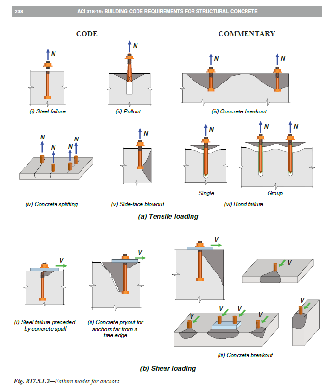
ACI 318-19 Fig. R17.5.1.2 - Modos de rotura para âncoras
No IDEA StatiCa Connection, temos sido capazes de verificar as âncoras até agora, mas com algumas limitações, as verificações tinham de ser feitas manualmente. Esta lacuna é colmatada com o IDEA StatiCa Detail 3D, que expande a capacidade do engenheiro para avaliar o desempenho das âncoras em betão armado, incluindo a forma como as cargas são transferidas para a fundação e resistidas tanto pelo betão como pela armadura.
Embora o IDEA StatiCa Detail 3D não ofereça verificações como as que estamos habituados na norma que as define para betão simples, com a análise por Método dos Elementos Finitos é possível verificar se a região de betão armado consegue suportar a carga aplicada e prevenir a rotura do betão, o que corresponderia a essas condições.
As aplicações funcionam de forma independente e podem ser utilizadas separadamente, mas graças à ligação entre Connection e Detail, os engenheiros podem realizar verificações normativas iniciais em Connection e depois verificar a distribuição complexa de tensões e o desempenho da armadura em Detail como etapa complementar.
Capacidade de compressão do betão
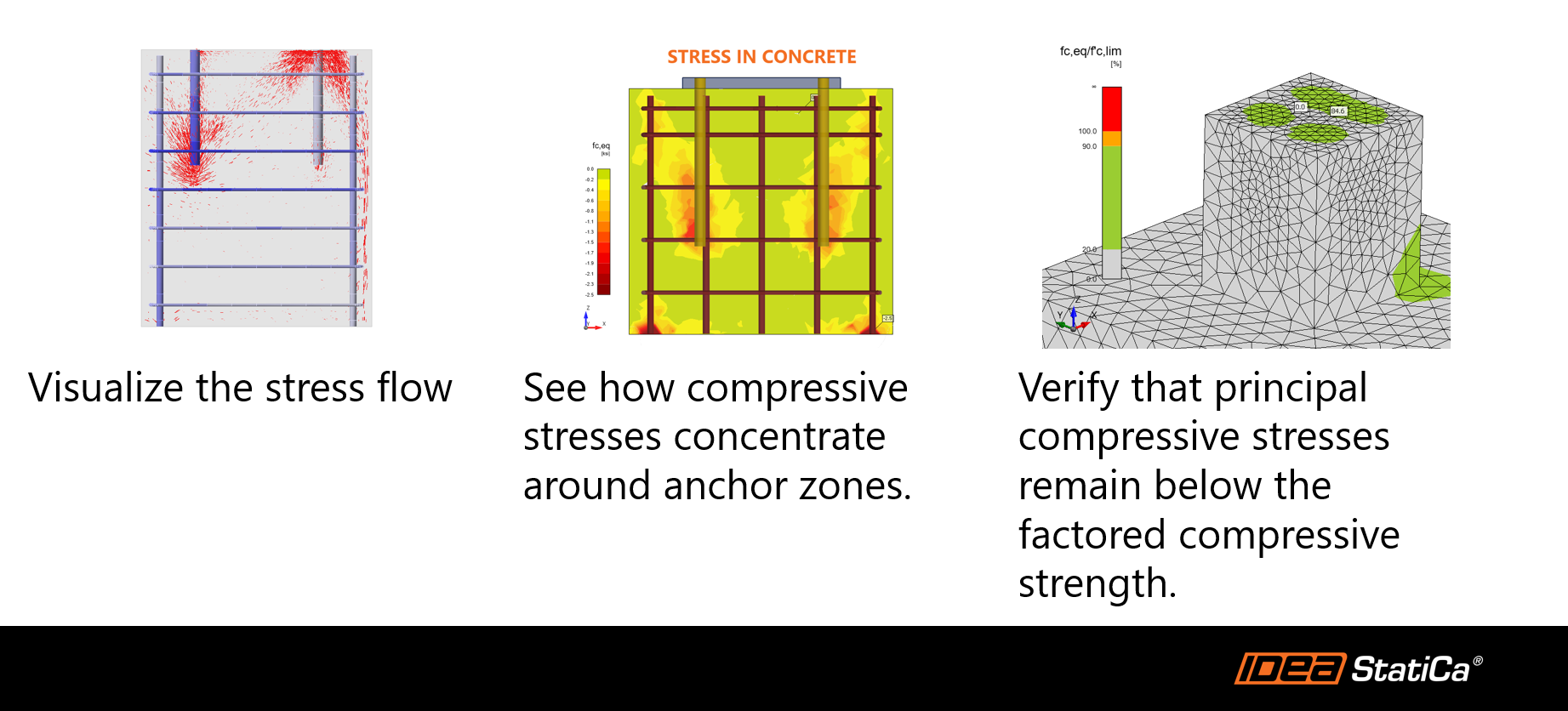
O IDEA StatiCa Detail 3D avalia a capacidade de compressão do betão utilizando um modelo tensão-deformação não linear parabólico-plástico baseado nas diretrizes da PCA. O software despreza a resistência à tração, em conformidade com o dimensionamento corrente de betão, e aplica fatores de redução de resistência de acordo com a ACI 318-19.
Isto permite aos engenheiros:
- Visualizar o fluxo de tensões através do betão.
- Ver como as tensões de compressão se concentram nas zonas das âncoras.
- Verificar que as tensões principais de compressão se mantêm abaixo da resistência à compressão de cálculo.
Capacidade de tração da armadura
A capacidade de tração da armadura é avaliada utilizando um modelo tensão-deformação elasto-plástico que está em conformidade com a ACI 318-19. Este modelo captura com precisão o comportamento da armadura não pré-esforçada, considerando tanto a tensão de cedência como o módulo de elasticidade. Por defeito, os efeitos de enrijecimento à tração são automaticamente incluídos, aumentando o realismo da análise ao contabilizar a interação entre a armadura e o betão envolvente.
O software avalia a força de tração em cada varão de armadura com base em dois componentes críticos:
- A força de tração direta no varão
- A tensão de aderência desenvolvida ao longo do comprimento embebido
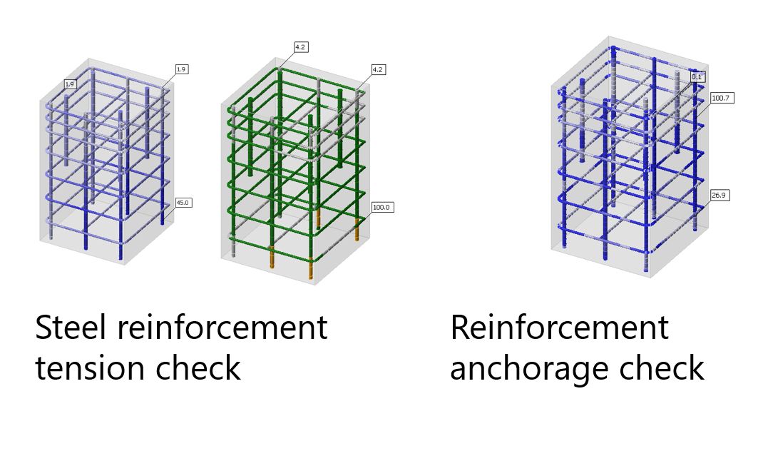
Esta abordagem detalhada garante que a força de tração total se mantém dentro da capacidade do varão, tendo em conta tanto os limites do material como as condições de ancoragem.
Agora, vamos percorrer as condições de cada modo de rotura da ACI uma a uma e as possibilidades que as aplicações podem oferecer.
Força de tração
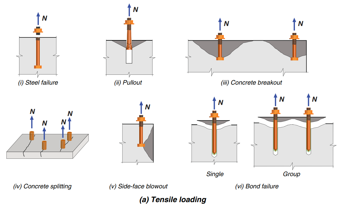
(i) Rotura do aço
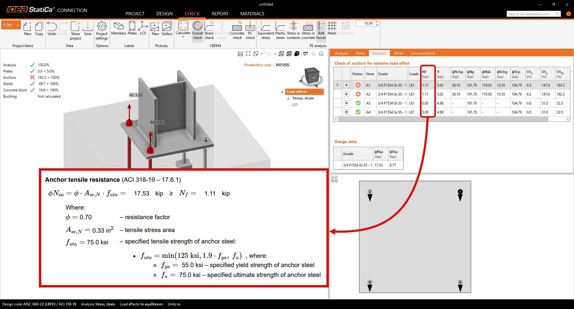
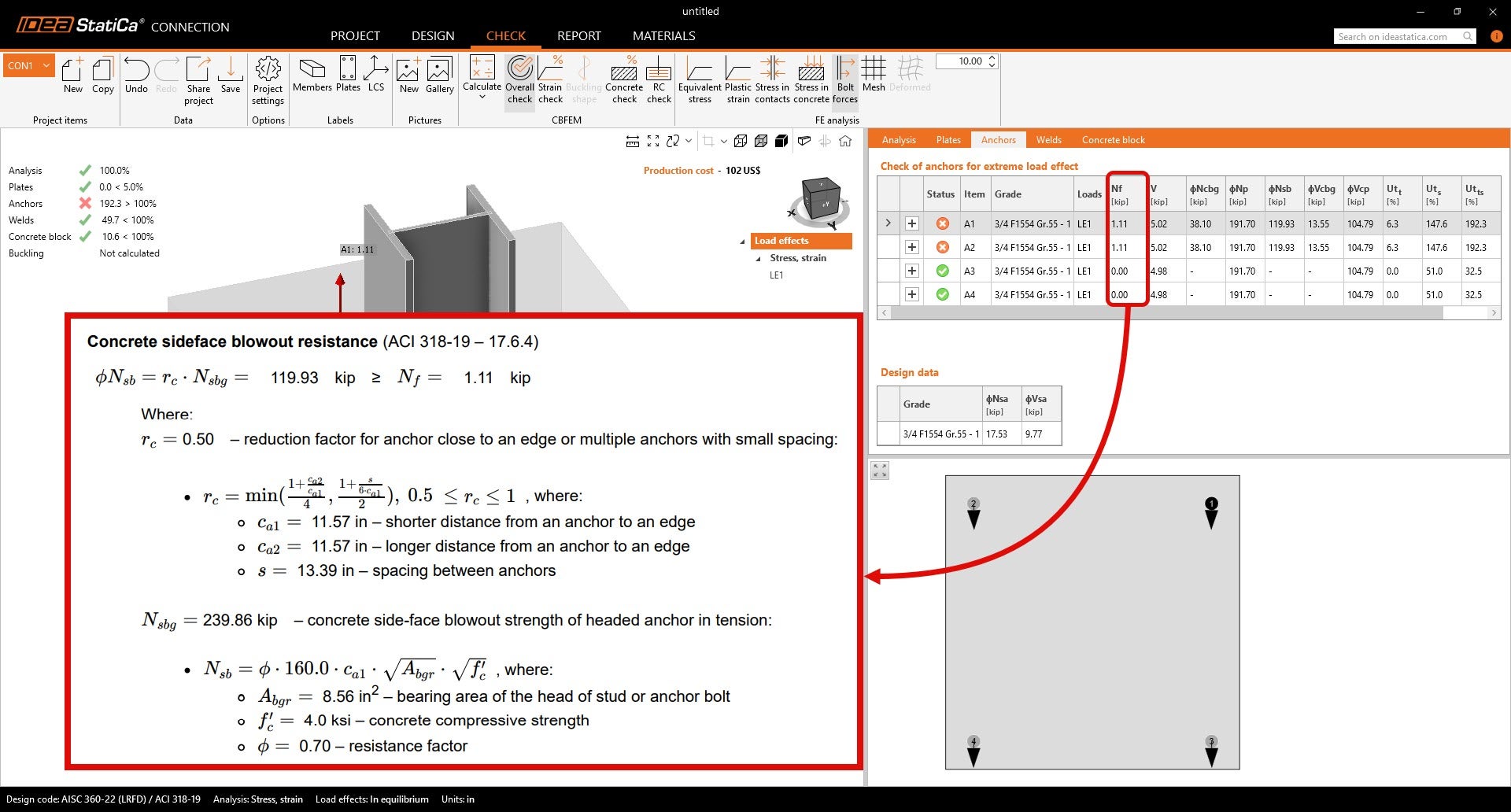
As verificações de rotura do aço no IDEA StatiCa são realizadas nos módulos Connection e Detail 3D de acordo com as disposições da ACI 318-19. No Connection, a rotura do aço é verificada através de uma verificação da capacidade de carga axial que compara as forças de tração aplicadas com a tensão de cedência reduzida do aço da âncora.
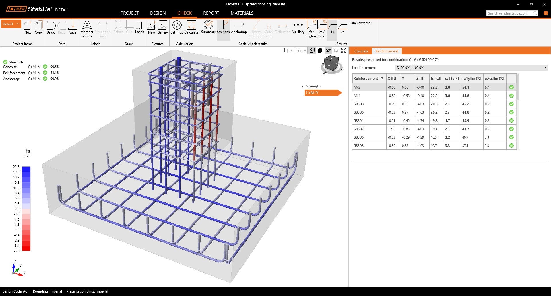
O Detail 3D complementa esta verificação modelando a armadura e o aço da âncora dentro do bloco de betão, proporcionando uma distribuição de forças mais detalhada e verificando que os elementos de aço se mantêm dentro dos seus limites elasto-plásticos.
(ii) Arrancamento
No Connection, as verificações de arrancamento baseiam-se em fórmulas empíricas da ACI 318 que têm em conta a geometria da âncora e a resistência do betão, aplicando os fatores de redução de resistência adequados.
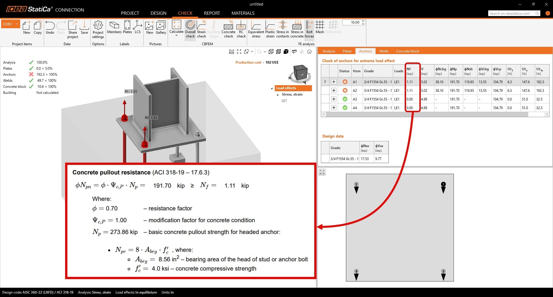
O Detail 3D melhora as verificações de arrancamento modelando as tensões de aderência ao longo do comprimento embebido da armadura. As forças de aderência são calculadas utilizando os resultados da análise, permitindo uma avaliação realista dos efeitos de interação e das condições variáveis de aderência. As âncoras adesivas também podem ser modeladas atribuindo a resistência de aderência de cálculo com base nos dados do fabricante.
(iii) Rotura por cone de betão
A rotura por cone de betão pode ser verificada no Connection. No entanto, no Connection, a rotura por cone de betão à tração é calculada utilizando fórmulas normativas que apenas consideram betão simples.
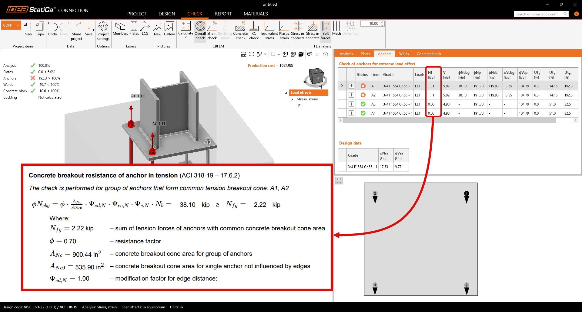
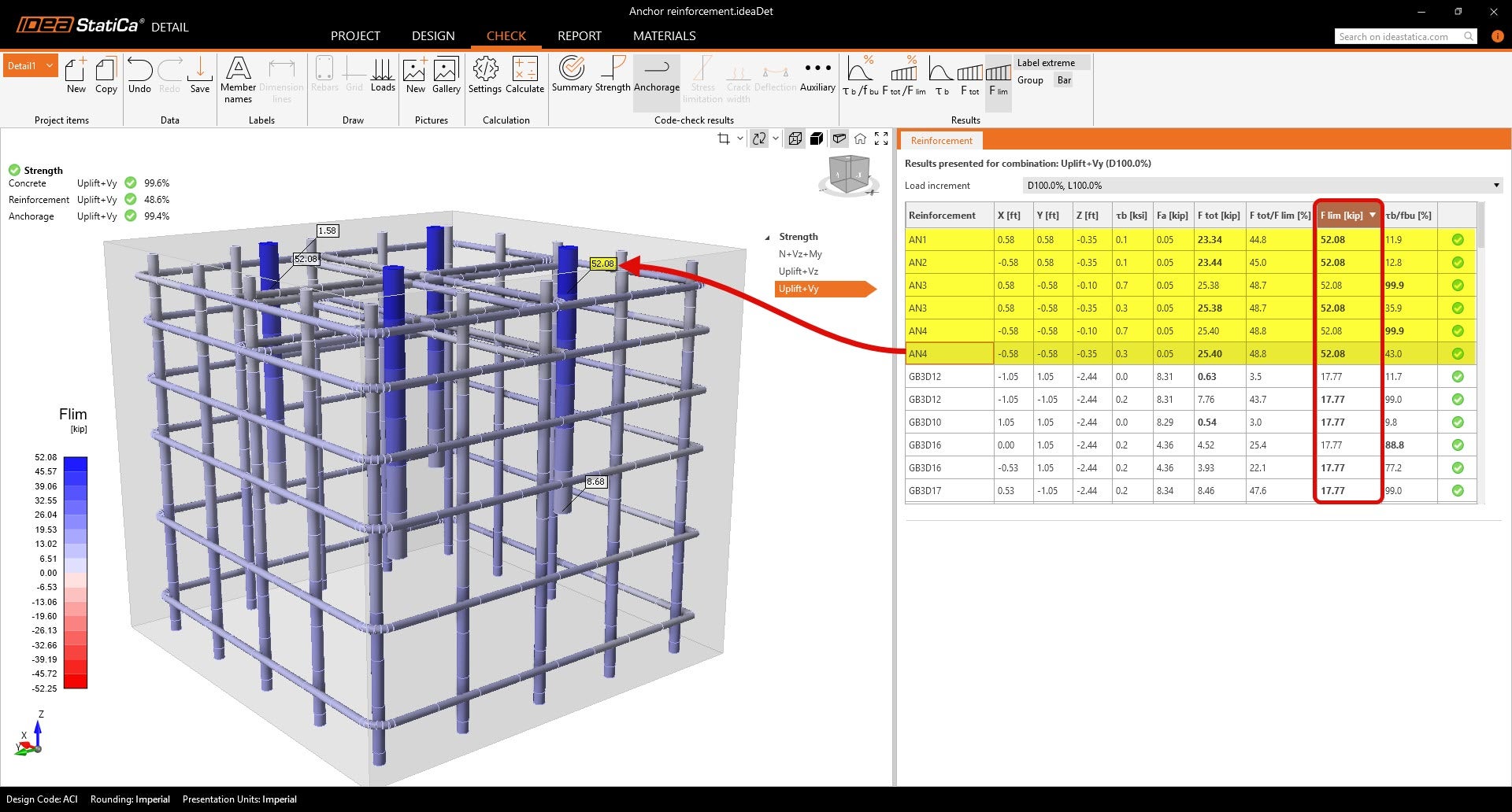
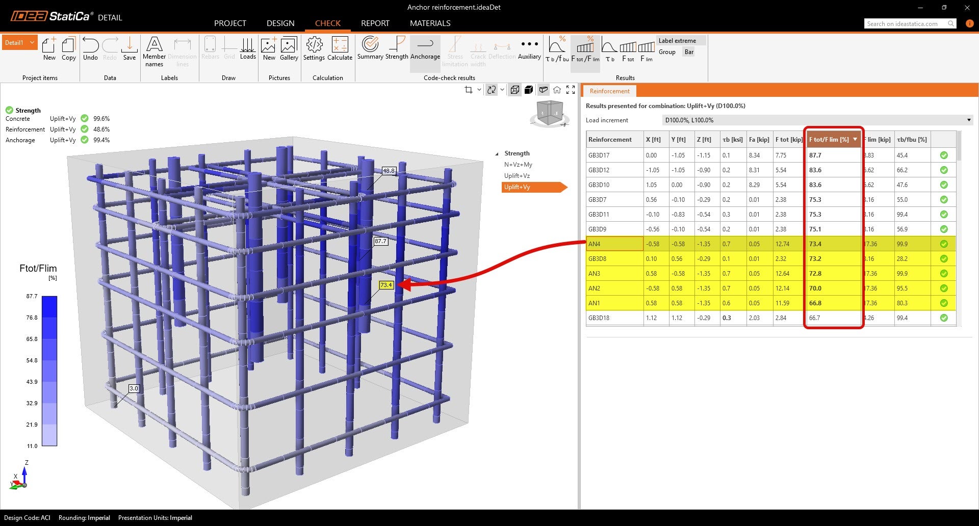
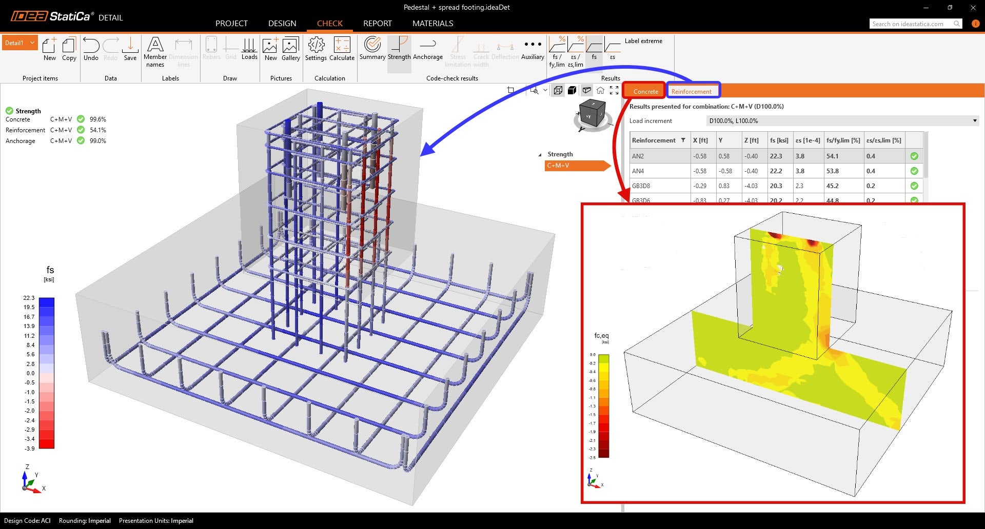
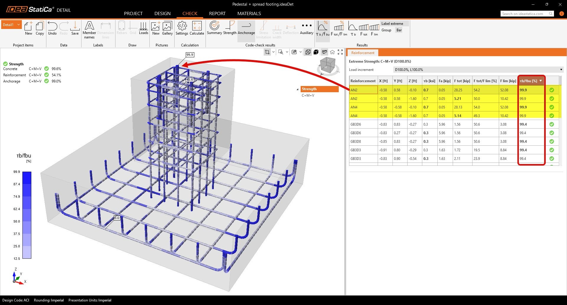
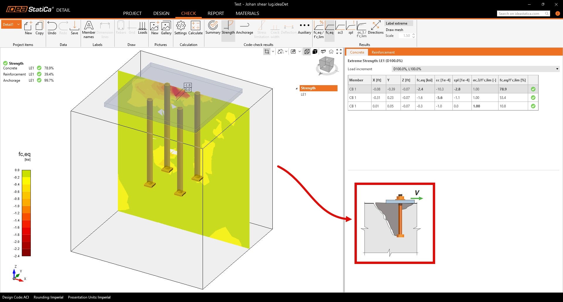
Por conseguinte, caso o cone de betão falhe, é adequado prosseguir para o IDEA StatiCa Detail, onde é fornecida uma análise do bloco armado completo. A resistência à tração do betão é conservadoramente desprezada, o que significa que a capacidade resistente para a rotura por cone é, em grande medida, determinada pela quantidade de armadura especificada. O Detail compara as tensões principais equivalentes máximas com as resistências de cálculo do betão, proporcionando uma verificação detalhada e precisa da resistência à rotura por cone sob cenários de carregamento complexos.
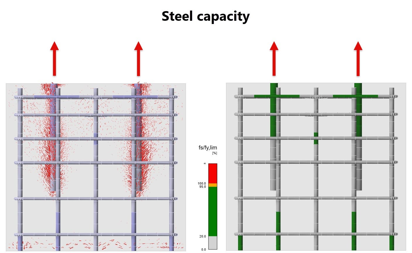
Na figura abaixo, pode ver as direções das tensões principais que indicam a forma do cone acima mencionado. Na parte direita, pode ver os valores das tensões no betão, que são avaliados com os valores limite.
(iv) Fendilhação do betão
Não é possível avaliar este modo de rotura no Connection. No entanto, no Detail 3D, a fendilhação é tipicamente mitigada pela armadura que controla a propagação de fissuras. O software permite aos engenheiros visualizar os campos de tensões e deformações tanto na armadura (sob tração e compressão) como no betão envolvente (sob compressão). Esta informação ajuda a confirmar que a armadura previne eficazmente a rotura por fendilhação.
(v) Rotura lateral por arrancamento
Para betão simples, o Connection oferece verificações empíricas de acordo com as disposições da ACI 318.
Para elementos estruturais armados, este modo de rotura é abrangido pela análise de resistência do betão do Detail 3D. Aqui, as forças de tração são principalmente resistidas pela armadura, com o betão a suportar a compressão, o que o IDEA StatiCa modela com precisão.
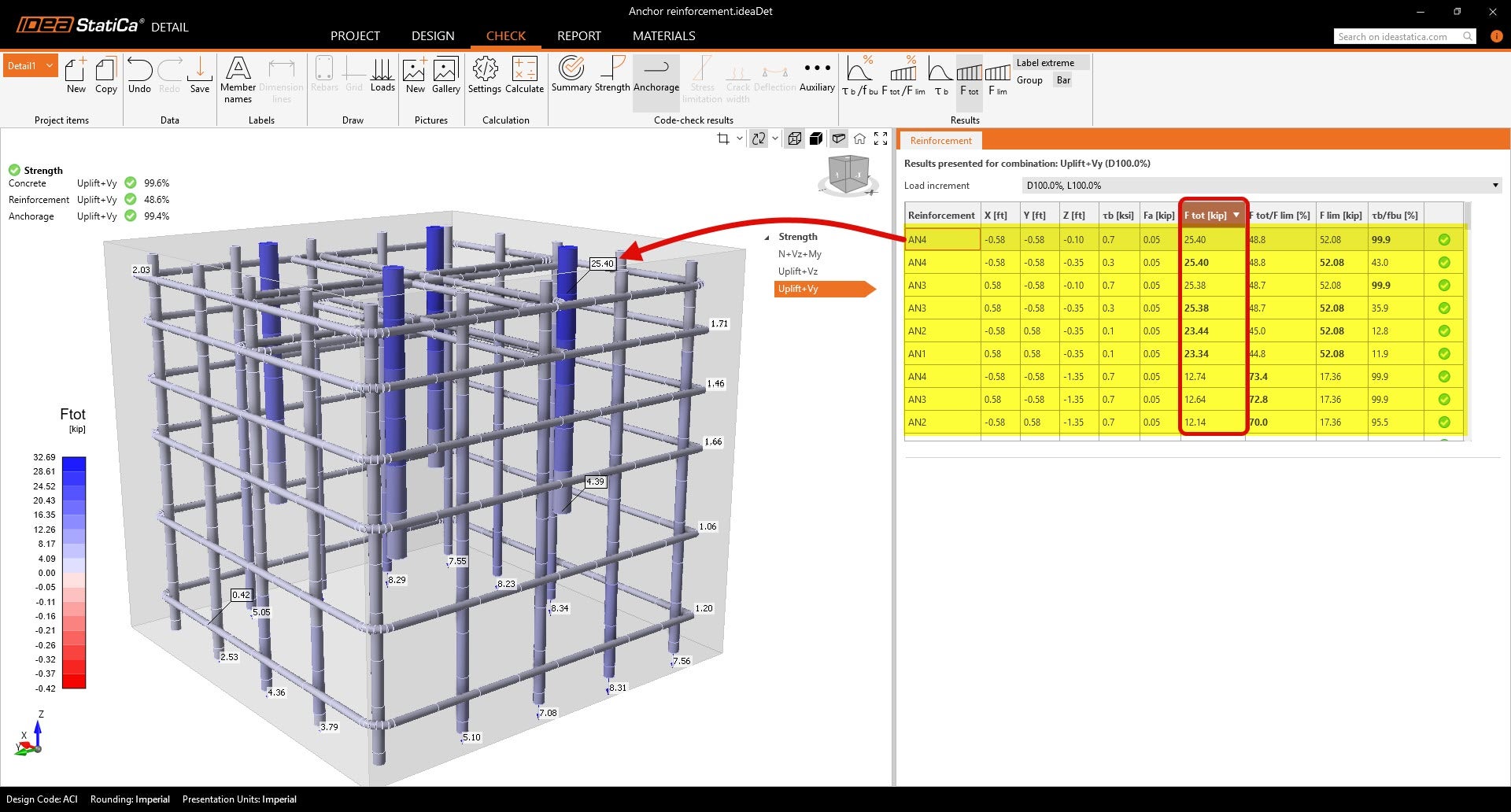
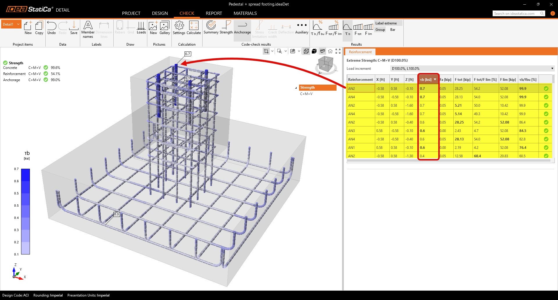
(vi) Rotura por perda de aderência
A rotura por perda de aderência refere-se à perda de transferência de força entre a armadura e o betão devido a adesão ou comprimento de embebimento inadequados. Este modo de rotura não é possível de capturar na aplicação Connection, uma vez que o betão é apenas não armado.
O Detail 3D avalia explicitamente as distribuições de tensão de aderência ao longo dos varões de armadura utilizando análise por elementos finitos. Isto permite a verificação da capacidade de aderência para além de simples fórmulas empíricas, considerando disposições complexas de armadura e condições do betão.
Carregamento de corte
A ACI classifica as roturas induzidas por corte em vários tipos para âncoras e blocos de betão, incluindo rotura do aço com esmagamento do betão, arrancamento do betão e rotura por cone de betão (i, ii & iii).
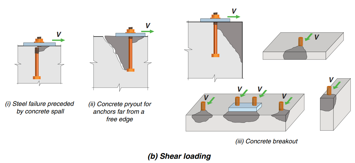
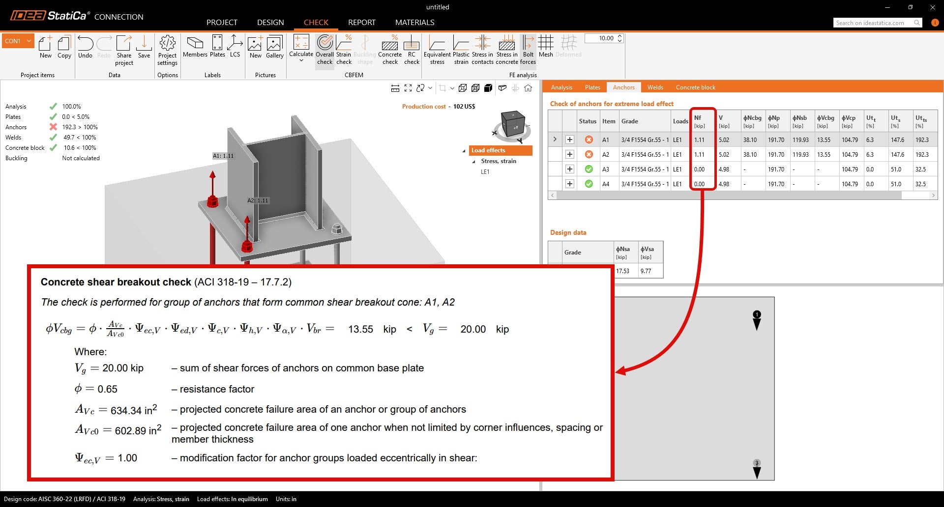
A figura abaixo mostra esquematicamente que tipo de rotura pode ser verificado com a aplicação Connection e também que comportamento pode ser coberto utilizando betão armado e, portanto, a análise em Detail. O IDEA StatiCa Connection utiliza fórmulas empíricas da AISC 360 para o dimensionamento de âncoras (CBFEM). Todos os tipos de rotura causados por força de corte podem ser verificados na aplicação Connection.
No IDEA StatiCa Detail 3D, o corte pode ser transferido por atrito, âncoras ou chaveta de corte. É importante referir que apenas a fundação é verificada. As âncoras/chaveta de corte devem ser verificadas no Connection ou noutro local. Importa novamente sublinhar que apenas é necessário betão armado.
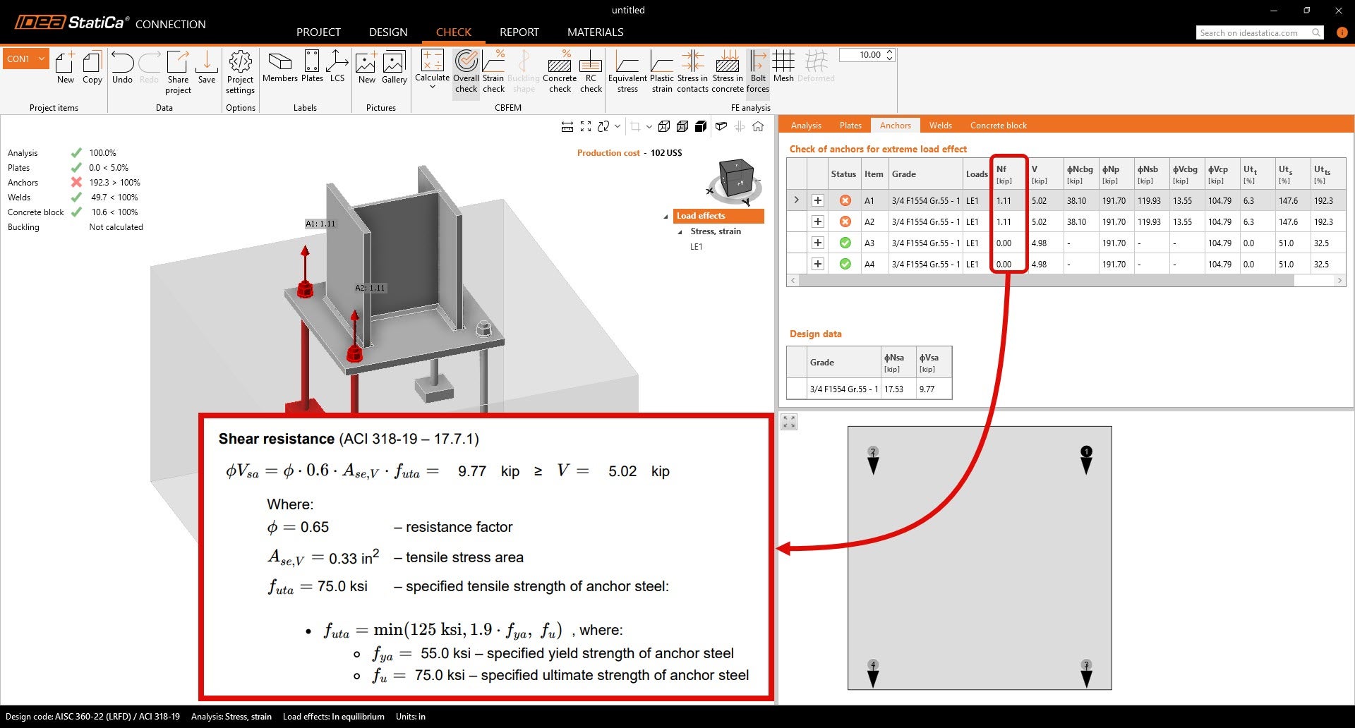
(i) Rotura do aço precedida de esmagamento do betão
Este modo de rotura ocorre quando as forças de corte provocam tanto a cedência do aço da âncora como o esmagamento (fraturação superficial) do betão envolvente. O IDEA StatiCa Connection avalia esta rotura aplicando as fórmulas de resistência ao corte da ACI para âncoras, garantindo que a interação entre o aço e o betão sob cargas de corte é devidamente contabilizada. Esta verificação não está disponível no Detail 3D, que se centra na modelação detalhada do betão e da armadura em vez da resistência ao corte do aço das âncoras.
(ii) Arrancamento do betão para âncoras afastadas de um bordo livre
O arrancamento do betão envolve a rotura do betão abaixo da placa de base da âncora devido a tensões de corte. Este modo é avaliado exclusivamente no Connection, utilizando fórmulas empíricas da ACI que consideram a profundidade de embebimento, a resistência do betão e os fatores de carga.
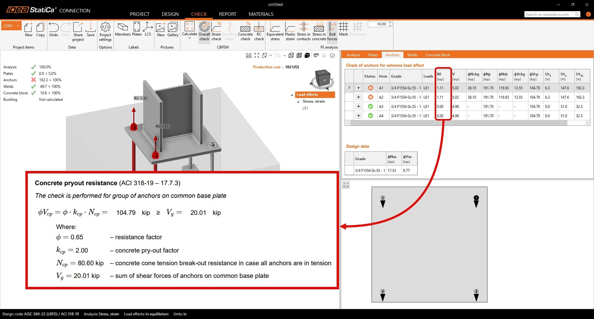
Complementando isto, o Detail 3D avalia a capacidade de corte da própria fundação de betão, oferecendo uma análise detalhada de tensões da região de betão afetada pelas cargas de corte.
(iii) Rotura por cone de betão
A rotura por cone de betão sob corte é um modo de rotura em que as forças de corte provocam a fraturação do betão e a formação de uma superfície de rotura em forma de cunha ou cone, iniciando-se na âncora e propagando-se em direção ao bordo livre. No IDEA StatiCa Connection, esta rotura é avaliada para betão simples utilizando fórmulas de dimensionamento empíricas da ACI 318-19.
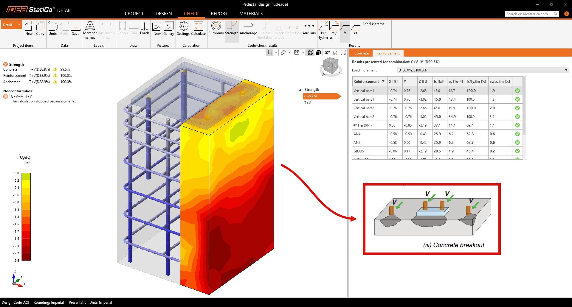
No Detail 3D, o software utiliza análise por Método dos Elementos Finitos para modelar a distribuição real de tensões e os mecanismos de rotura dentro do bloco de betão. Ao visualizar as tensões principais e a transferência de forças de corte através da armadura, o Detail 3D pode verificar se o betão armado consegue prevenir ou resistir adequadamente à rotura por cone sob corte.
Verificações de pormenorização
Embora o IDEA StatiCa Detail 3D possa analisar e verificar uma vasta gama de modos de rotura utilizando análise não linear por elementos finitos, as verificações de pormenorização, como as especificadas no Capítulo 17 da ACI 318, não estão cobertas no Detail 3D. Estas incluem requisitos como distâncias mínimas ao bordo, espaçamento entre âncoras, profundidades de embebimento e cobrimento do betão.
É da responsabilidade do engenheiro verificar estes requisitos de pormenorização de forma independente e garantir que a geometria de entrada no Detail 3D cumpre todas as disposições de pormenorização exigidas pela norma antes de executar a análise.
A aplicação Detail centra-se na resposta estrutural e na distribuição de tensões do bloco de betão e da armadura, mas não assinala nem verifica as dimensões mínimas de pormenorização ou as disposições das âncoras de acordo com as regras de pormenorização da ACI. Entradas precisas e conformes com a norma são essenciais para obter resultados significativos e válidos.