General introduction for the structural design of concrete details
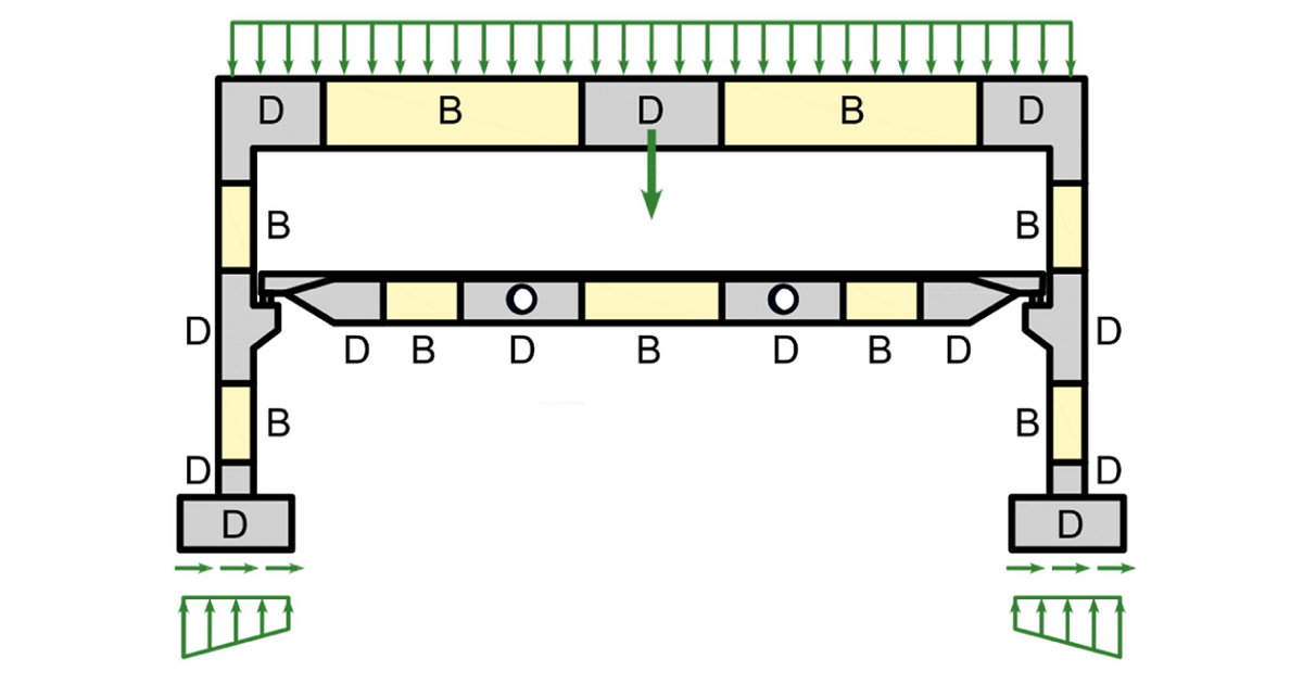
The design and assessment of concrete elements are normally performed at the sectional (1D-element) or point (2D-element) level. This procedure is described in all standards for structural design, e.g., in (EN 1992-1-1), and it is used in everyday structural engineering practice. However, it is not always known or respected that the procedure is only acceptable in areas where Bernoulli-Navier hypothesis of plane strain distribution applies (referred to as B-regions). The places where this hypothesis does not apply are called discontinuity or disturbed regions (D-Regions). Examples of B and D regions of 1D-elements are given in (Fig. 1). These are, e.g., bearing areas, parts where concentrated loads are applied, locations where an abrupt change in the cross-section occurs, openings, etc. When designing concrete structures, we meet a lot of other D-Regions such as walls, bridge diaphragms, corbels, etc.
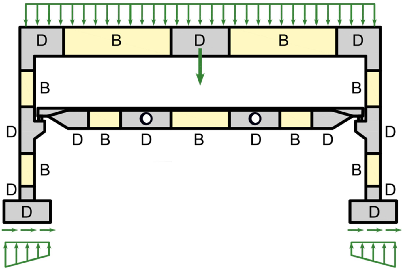
\[ \textsf{\textit{\footnotesize{Fig. 1\qquad Discontinuity regions (Navrátil et al. 2017)}}}\]
In the past, semi-empirical design rules were used for dimensioning discontinuity regions. Fortunately, these rules have been largely superseded over the past decades by strut-and-tie models (Schlaich et al., 1987) and stress fields (Marti 1985), which are featured in current design codes and frequently used by designers today. These models are mechanically consistent and powerful tools. Note that stress fields can generally be continuous or discontinuous and that strut-and-tie models are a special case of discontinuous stress fields.
Despite the evolution of computational tools over the past decades, Strut-and-Tie models are essentially still used as hand calculations. Their application for real-world structures is tedious and time-consuming since iterations are required, and several load cases need to be considered. Furthermore, this method is not suitable for verifying serviceability criteria (deformations, crack widths, etc.).
The interest of structural engineers in a reliable and fast tool to design D-regions led to the decision to develop the new Compatible Stress Field Method, a method for computer-aided stress field design that allows the automatic design and assessment of structural concrete members subjected to in-plane loading.
The Compatible Stress Field Method is a continuous FE-based stress field analysis method in which classic stress field solutions are complemented with kinematic considerations, i.e., the state of strain is evaluated throughout the structure. Hence, the effective compressive strength of concrete can be automatically computed based on the state of transverse strain in a similar manner as in compression field analyses that account for compression softening (Vecchio and Collins 1986; Kaufmann and Marti 1998) and the EPSF method (Fernández Ruiz and Muttoni 2007). Moreover, the CSFM considers tension stiffening, providing realistic stiffnesses to the elements, and covers all design code prescriptions (including serviceability and deformation capacity aspects) not consistently addressed by previous approaches. The CSFM uses common uniaxial constitutive laws provided by design standards for concrete and reinforcement. These are known at the design stage, which allows the partial safety factor method to be used. Hence, designers do not have to provide additional, often arbitrary material properties as are typically required for non-linear FE-analyses, making the method perfectly suitable for engineering practice.
To foster the use of computer-aided stress fields by structural engineers, these methods should be implemented in user-friendly software environments. To this end, the CSFM has been implemented in IDEA StatiCa Detail; a new user-friendly commercial software developed jointly by ETH Zurich and the software company IDEA StatiCa in the framework of the DR-Design Eurostars-10571 project.