
Voetplaat op betonnen sokkel geïntegreerd ontwerp (ACI)
1 Nieuw project
Start de IDEA StatiCa Connection. Alles begint op de kaart Staal.
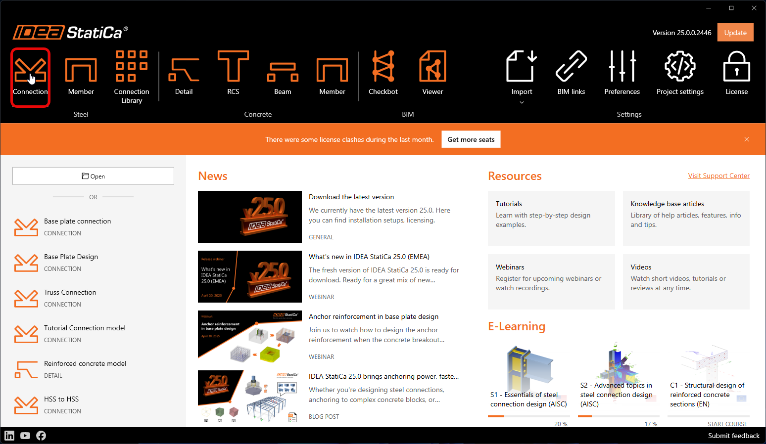
Behoud de standaardinstellingen voor de verankeringstopologie en open de applicatie.
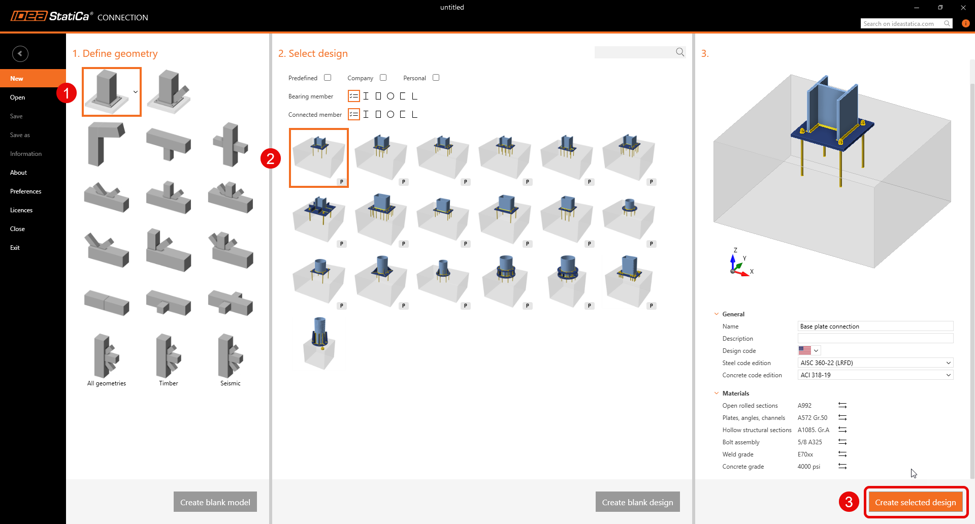
2 Ontwerp
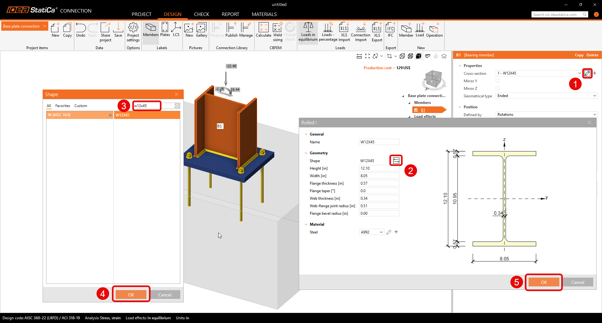
Voordat er aanpassingen worden gedaan, zorg ervoor dat de parametrische template wordt "Geëxplodeerd". De nieuwe parametrische templates bieden een snelle manier om eenvoudige verbindingen te bewerken door slechts enkele parameters te wijzigen. Om echter de volledige aanpassingsopties te bekijken, explodeer de parametrische template en krijg toegang tot de bewerkingen.

Begin met het aanpassen van de doorsnede-afmeting van de kolom in de template verbinding die zojuist is geopend. De nieuwe doorsnede is W12x45.
Pas de Voetplaat bewerking aan om de uiteindelijke topologie van het belaste betonblok te realiseren zoals hieronder weergegeven.
- Met Detail 3D kan afschuiving nu ook worden overgedragen via ankers, afschuif deuvels en wrijving.

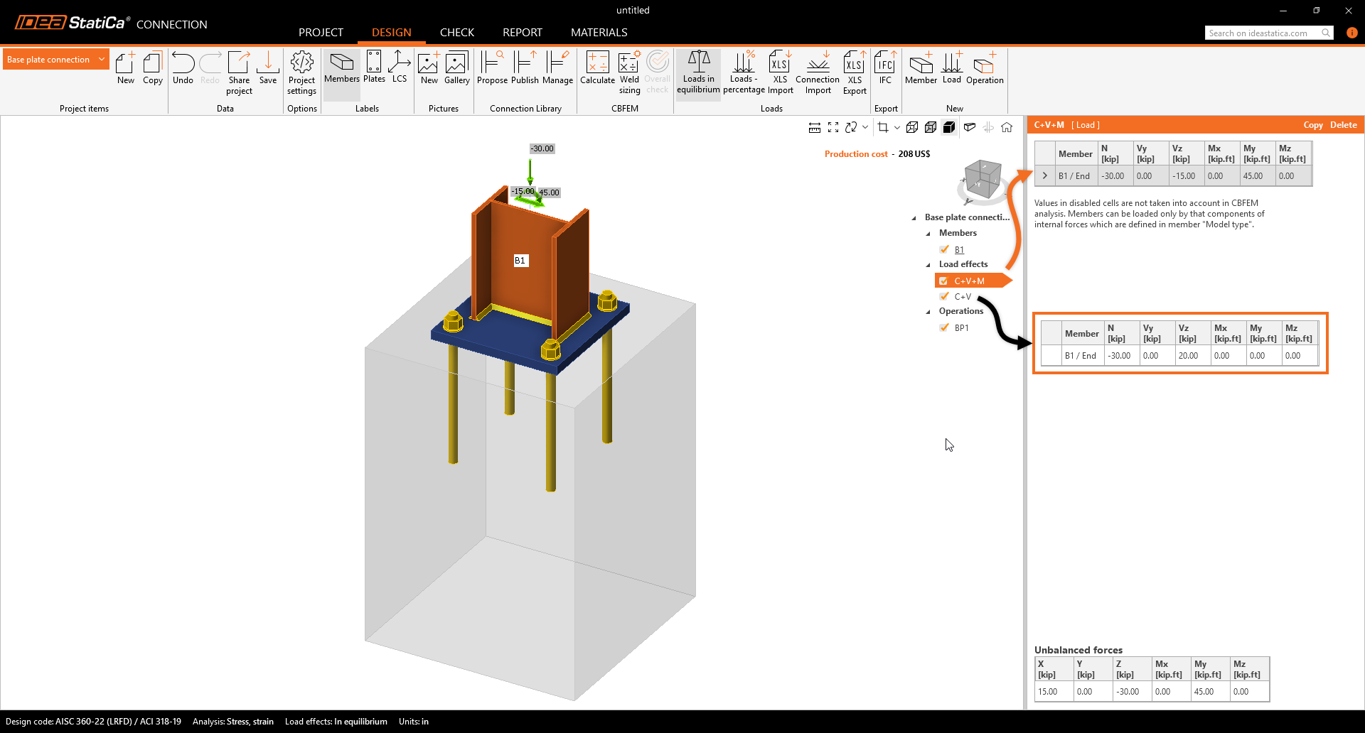
Voer de inwendige krachten in voor de twee lastgevallen zoals hieronder weergegeven. De inwendige krachten veroorzaken drukspanning op het contactvlak tussen de grond en het betonblok. Standaard wordt aangenomen dat het betonblok gescheurd is.
3 Controle
Ga naar de kaart, controleer en bereken. De normtoetsing toont het bezwijkmechanisme van de ankers. Laten we dit verder onderzoeken.

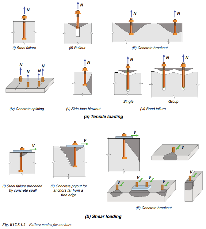
Laten we de mogelijke bezwijkvormen voor trek en afschuiving onderzoeken volgens ACI 318 Section 17.4.
Bekijk de Gedetailleerde Controle van de Ankers, omdat deze op de eerste pagina een afwijking toont. Dit informeert u over de uitgevoerde normtoetsingen en wat er precies niet voldoet. Het wordt aanbevolen de nodige maatregelen te nemen om dit probleem op te lossen.
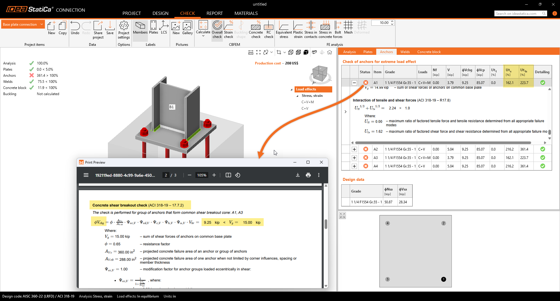
Analyse van de niet-voldoende Ankercontroles:
- Het probleem wordt veroorzaakt door de Betonuitbraakweerstand van ankers.
- Dit probleem kan eenvoudig worden opgelost in IDEA StatiCa Detail, aangedreven door de 3D CSFM methode. Het helpt het model van ongewapend beton gescheurde blokken in IDEA StatiCa Connection te overwinnen.
4 Export
De intern ontwikkelde applicatie IDEA StatiCa Connection beschikt nu over een krachtige BIM-koppeling naar Detail, waarmee het ontwerp en de controle van gewapende betonblokken met meerdere combinaties mogelijk is.
Vereisten voor export:
- Het model moet vooraf berekend zijn en de resultaten moeten zijn opgenomen
Ga naar de kaart Controle -> RC controle -> Opslaan.
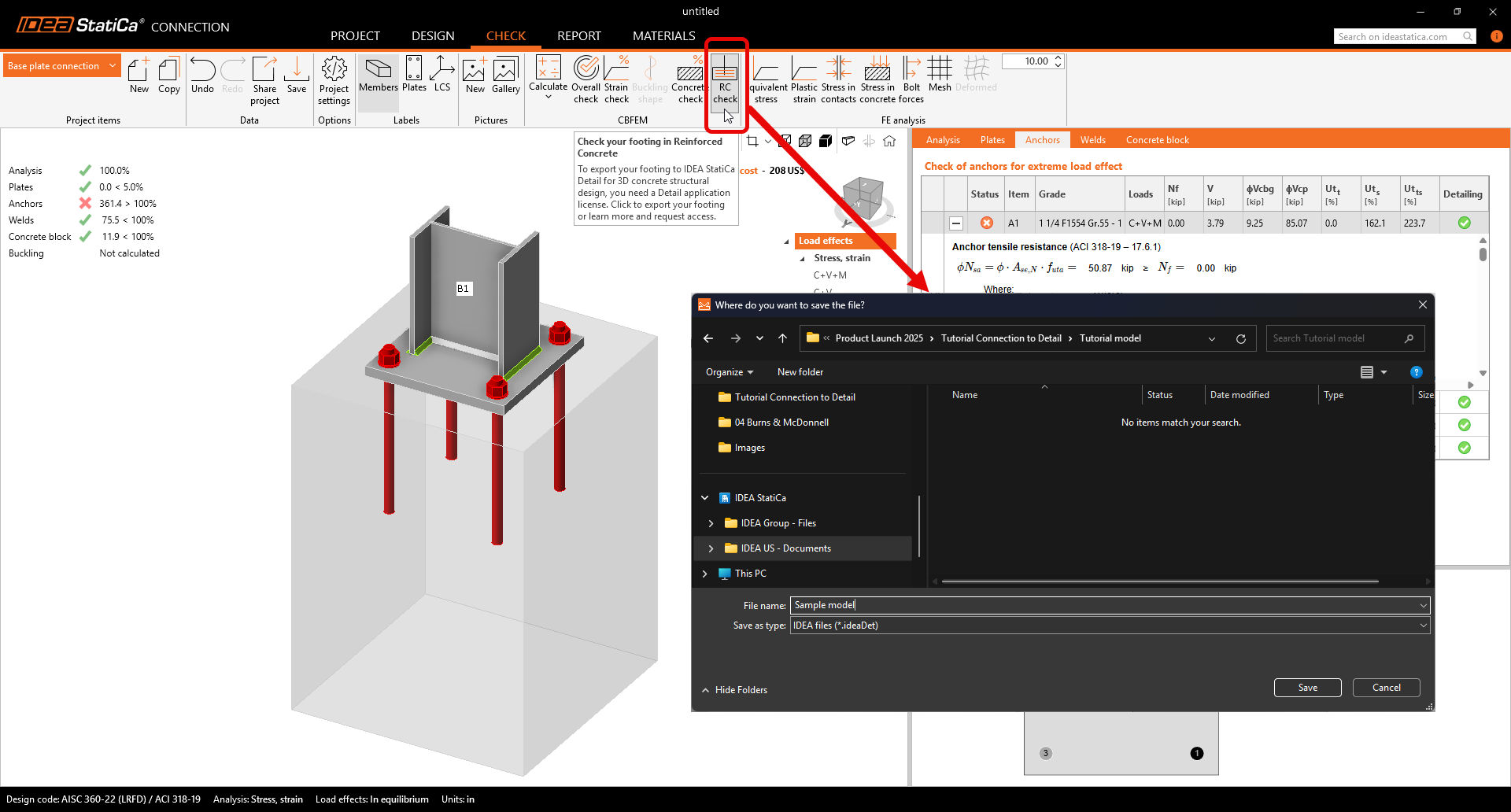
De export is alleen toegestaan voor de verankeringstopologie. De export maakt de overdracht mogelijk van:
- Het betonblok
- Ankers
- De voetplaat
- Belastingen
Aanvullende informatie en parameters die worden ingesteld op basis van de overeenkomstige instellingen in de verbinding:
- Afschuivingsoverdracht (via ankers, afschuif deuvels en wrijving)
- Materiaal
- Verankeringstype: Achteraf aangebrachte (Adhesief) / ingestorte ankers
- Verankeringstype aan het uiteinde: Ankerplaat/Recht/Gebogen/Haak/Lus
- Wrijvingscoëfficiënt
5 Ontwerp
In dit gedeelte kunt u staven, opleggingen, belastingen & combinaties en wapeningssamenstelling aanpassen.
Oplegging
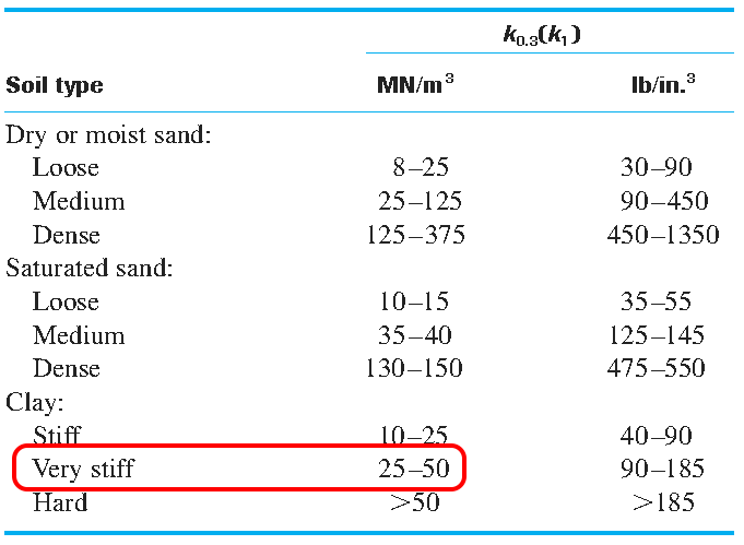
De grond heeft enige stijfheid, waarmee rekening moet worden gehouden voor een nauwkeurig ontwerp. De Oppervlakte-oplegging maakt stijfheid in alle drie richtingen mogelijk en is standaard inactief in trek (randvoorwaarde niet-lineariteit).
- Wees voorzichtig bij het maken van aannames over randvoorwaarden. In het geval van niet-lineariteit, als de momenten vrij groot zijn, kan de oplegging van het betonblok in trek tijdens de analyse omslaan, wat grote rotaties veroorzaakt. Dit kan leiden tot een divergerend model door de flexibele lichaambeweging.
Omdat ons model een sokkel is waarop de staven worden doorgetrokken naar de padfundering, deselecteer de optie voor uitsluitend druk-oplegging in de Z-richting. Dit maakt continue wapening mogelijk die verbinding maakt met de fundering.

Overdrachtsmiddelen
De ankers worden overgenomen uit IDEA StatiCa Connection. Er kunnen twee typen ankers worden geselecteerd.
Ingestorte ankers:
- Vooraf geïnstalleerde ankers met dezelfde eigenschappen in aanhechting als de wapeningsstaven
Achteraf aangebrachte (Adhesieve) ankers:
- Achteraf aangebrachte (Adhesieve/Chemische ankers) met de mogelijkheid om de aanhechtingssterkte aan te passen op basis van de werkelijke aanhechtingssterkte.

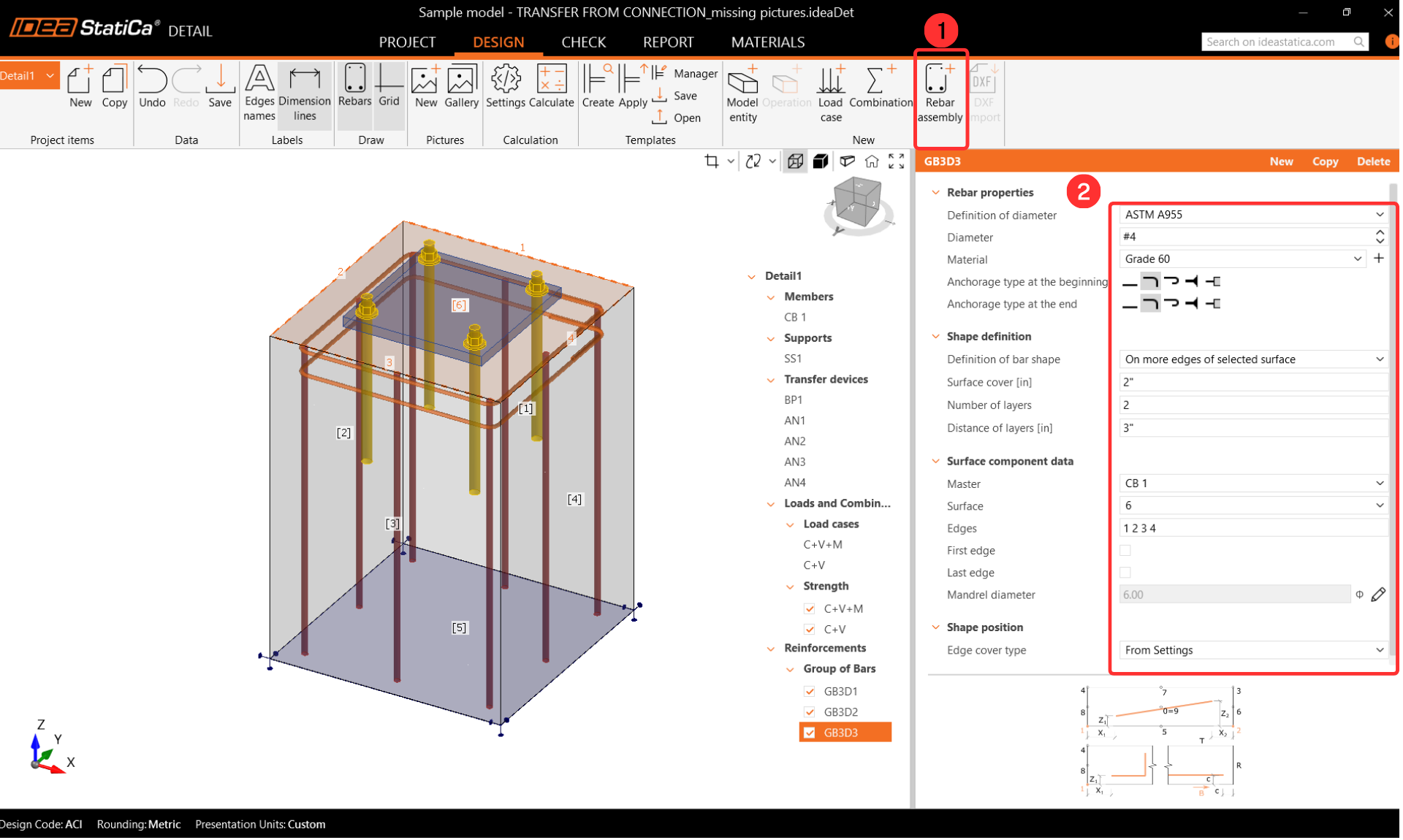
Modellering van staalwapening
Stel de betondekking in op 2 in, wat wordt gebruikt als standaardwaarde voor de wapening.

Begin met het wapenen van de sokkel door de staven toe te voegen. Selecteer de Wapening-Samenstelling(1)-->Groep van staven 3D(2) en vul de parameters in.

We moeten nu de rest van de staven toevoegen. Kopieer de bewerking en wijzig de parameters die rood omcirkeld zijn zoals hieronder weergegeven.

Om de initiële beugels toe te voegen, voeg een nieuwe groep staven toe. De volgende stappen geven de benodigde invoer voor de parameters.
Kopieer de bewerking en wijzig alleen de Vormdefinitie om de rest van de beugels aan de sokkel toe te voegen.

Het laatste onderdeel is het toevoegen van de afschuivingswapening aan de sokkel. In dit model voegen we afschuivingswapening toe voor beide richtingen.


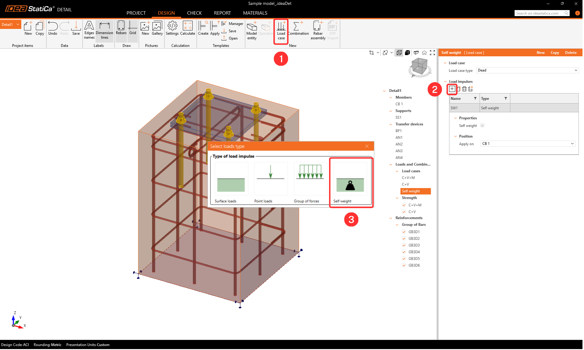
Belastingen en combinaties
Combinaties worden overgenomen uit IDEA StatiCa Connection. Voor meer informatie over de importdetails, volg de link - Import van verankering van Connection naar Detail.

Maak een lastgeval Eigengewicht.
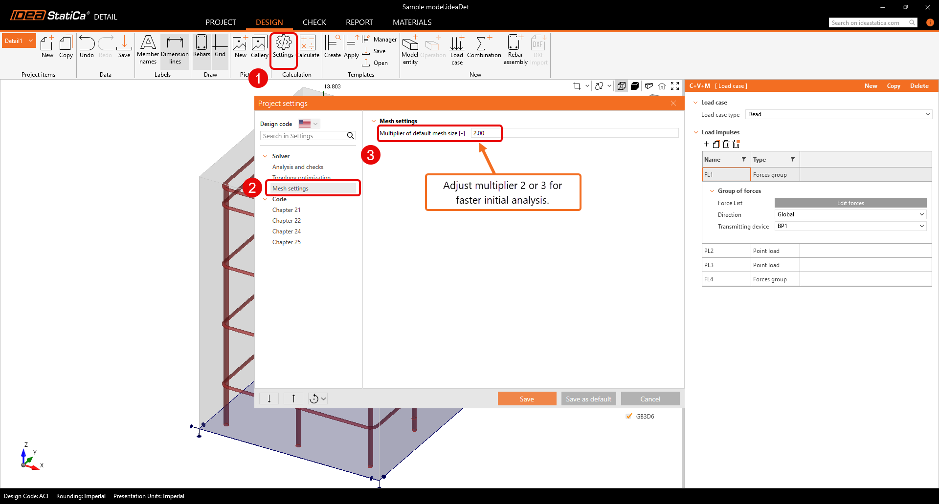
6 Controle
Voordat u de analyse uitvoert, raden we sterk aan de mesh vermenigvuldiger te wijzigen naar twee of drie om de berekening te versnellen. Deze stap is niet verplicht, maar kan de rekentijd verkorten en helpt bij het opsporen van eventuele divergentieproblemen. Als alles soepel verloopt en er geen problemen optreden, kunt u terugschakelen naar een vermenigvuldiger van één.

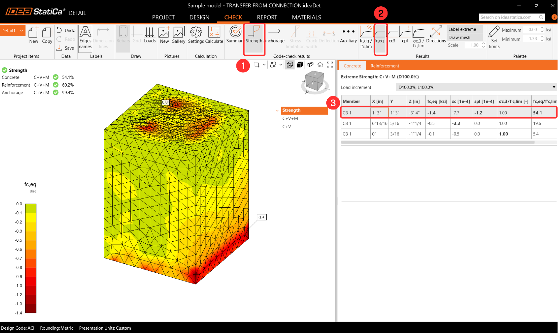
Resultaten
Equivalente hoofdspanning
De equivalente hoofdspanning (EPS) in beton wordt bepaald op basis van het volumegedrag van het betonblok. De gebieden die de hoogste belasting ondervinden worden geïdentificeerd en gemarkeerd. Meer informatie over equivalente hoofdspanning is opgenomen in dit artikel van de theoretische achtergrond.
Spanning in wapeningsstaven
Tijdens de Wapeningscontrole kunnen de spanningen voor elke wapening worden bekeken. U kunt ook de volgorde van de resultaten wijzigen om de meest belaste wapening te bekijken. Uit de opnieuw geordende resultaten is het sneller te zien welke ankers en wapeningsstaven het meest worden benut.

Bij het weergeven van de benuttingsgraad van de wapening kan de gebruiker duidelijk zien welke wapening bijdraagt aan het overdragen van de belasting en het voorkomen van betonkegelbezwijken.

Verankering
Controleer de Verankeringsinstellingen nogmaals en activeer de Totale kracht in ankers. De krachten in de ankers kunnen enigszins variëren door verschillen in de berekeningsmethoden voor het betonblok. De verschillen zijn echter niet significant.

Vervormingen
Ga naar Hulpfuncties en schakel de Vervorming in.
Het is niet noodzakelijk om een vervormingscontrole uit te voeren, maar het wordt sterk aanbevolen om na de analyse de vervorming te controleren om te verzekeren dat het model geen grote vervorming, grote rotatie of beschadigde eindige elementen vertoont. Dit geeft een overzicht van de analyseresultaten en helpt bij het identificeren van eventuele problemen die tijdens de analyse zijn opgetreden.

7 Rapport
Ga ten slotte naar de Rapportweergave/Afdrukken. IDEA StatiCa biedt een volledig aanpasbaar rapport om af te drukken of op te slaan in een bewerkbaar formaat.

U heeft het volledige verbindingsontwerp gecontroleerd volgens AISC en ACI 318. Het stalen deel werd gecontroleerd in IDEA StatiCa Connection, en het betonblok werd normgetoetst in IDEA StatiCa Connection en Detail.