
Proiectarea integrată a plăcii de bază pe soclu de beton (ACI)
1 Proiect nou
Rulați IDEA StatiCa Connection. Totul începe pe cardul Steel.
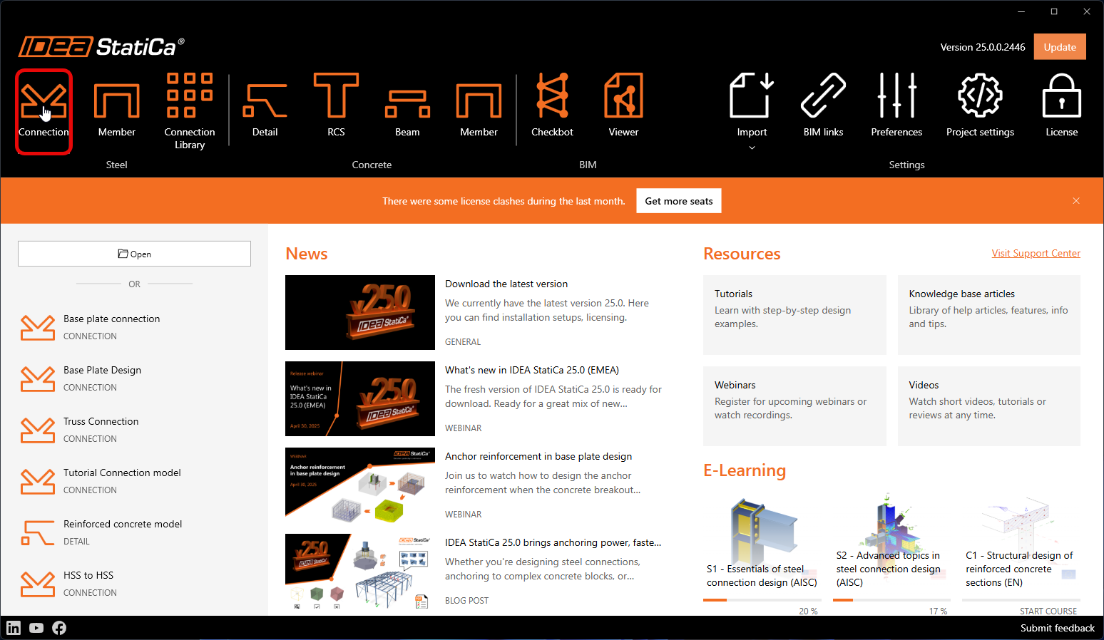
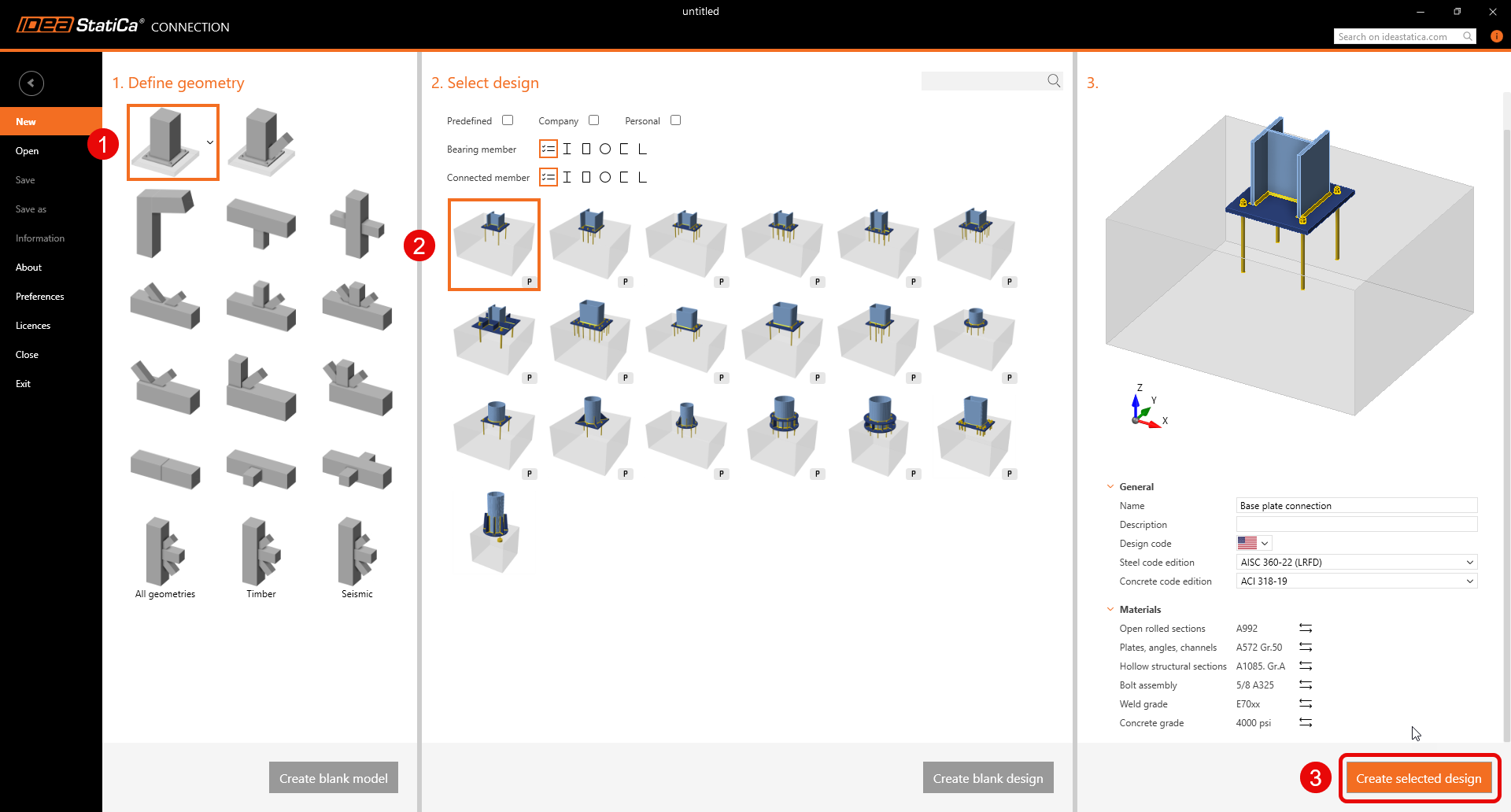
Păstrați setările implicite pentru topologia de ancorare și intrați în aplicație.
2 Proiectare
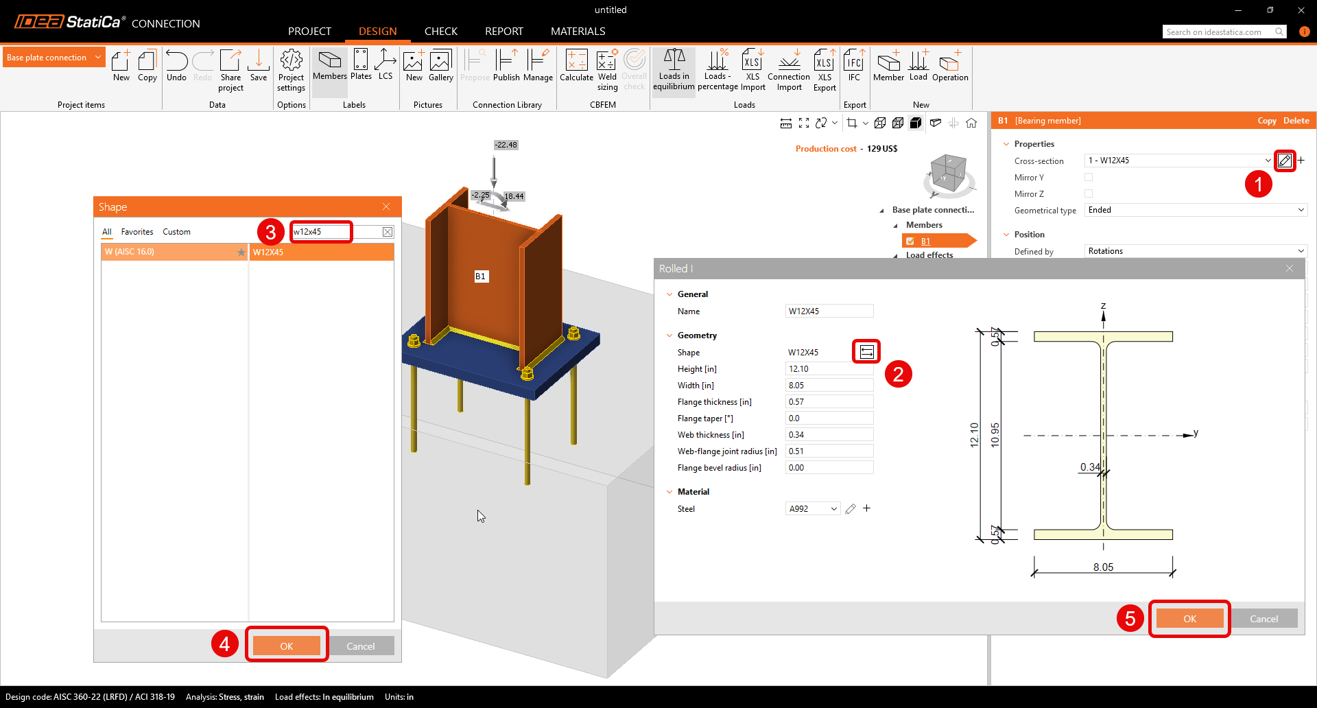
Înainte de a face orice ajustări, asigurați-vă că „Explodați" șablonul parametric. Noile șabloane parametrice oferă o modalitate rapidă de editare a îmbinărilor simple prin modificarea câtorva parametri. Cu toate acestea, pentru a vizualiza opțiunile complete de personalizare, explodați șablonul parametric și obțineți acces la operațiile de fabricație.

Începeți prin ajustarea dimensiunii secțiunii transversale a stâlpului din îmbinarea șablon care tocmai s-a deschis. Noua secțiune transversală este W12x45.
Modificați operația Placă de bază pentru a obține topologia finală a blocului de beton încărcat, așa cum este prezentat mai jos.
- Cu Detail 3D, forfecarea poate fi acum transferată și prin ancore, pivoți de forfecare și frecare.

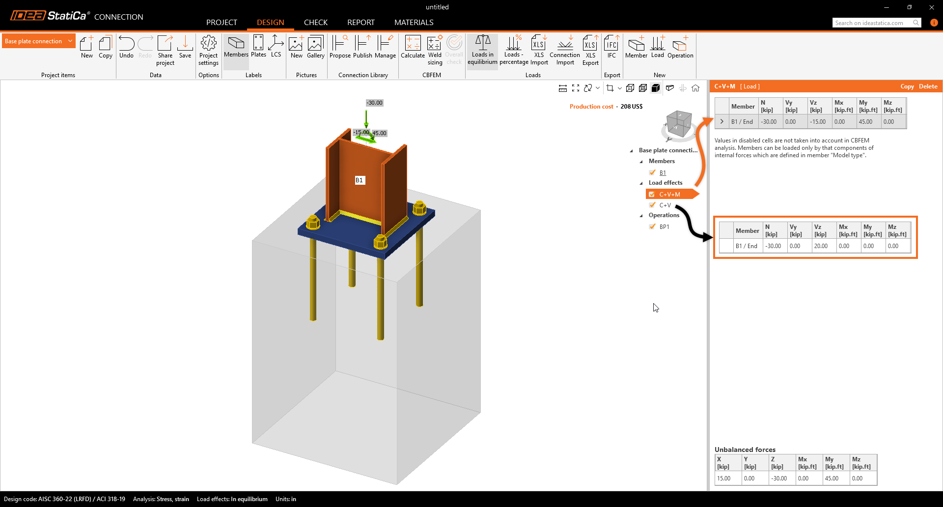
Introduceți forțele interioare pentru cele două cazuri de încărcare, așa cum este prezentat mai jos. Forțele interioare produc tensiuni de compresiune la contactul dintre teren și blocul de beton. În mod implicit, blocul de beton este considerat fisurat.
3 Verificare
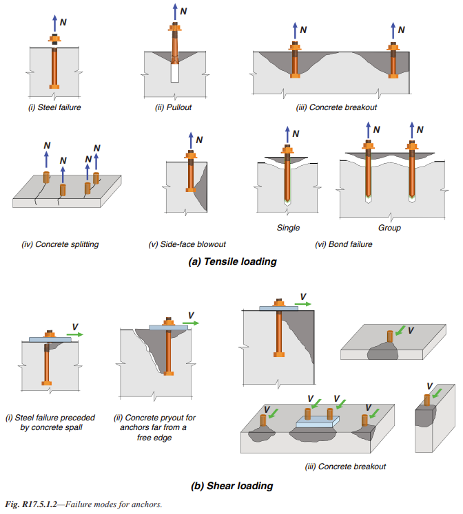
Treceți la card, verificați și calculați. Verificarea conform codului demonstrează modul de cedare al ancorelor. Să explorăm mai în detaliu.

Să explorăm cedările potențiale la întindere și forfecare conform ACI 318 Secțiunea 17.4.
Vă rugăm să consultați Verificarea Detaliată a Ancorelor, deoarece aceasta evidențiază o neconformitate pe prima pagină. Aceasta vă va informa despre verificările conform codului efectuate și despre ce anume nu corespunde. Se recomandă să luați măsurile necesare pentru a remedia această problemă.
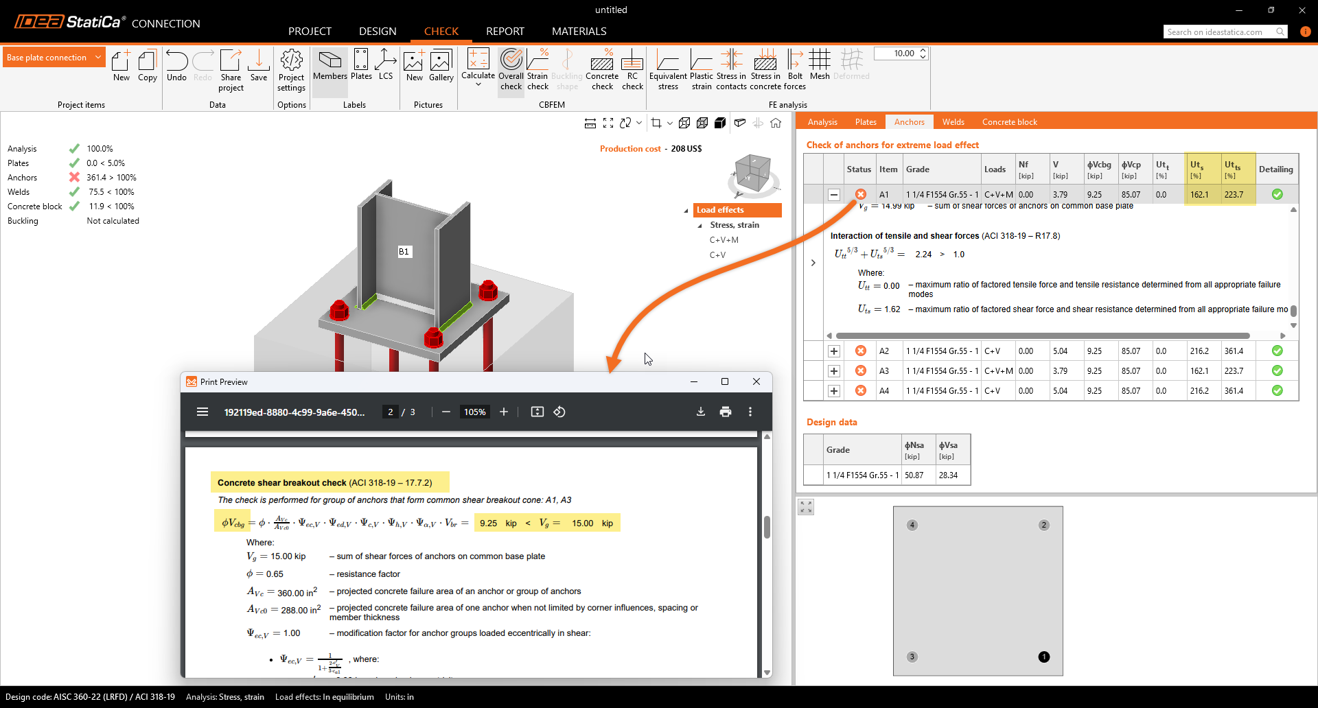
Analizând Verificările Ancorelor care nu corespund:
- Problema este cauzată de rezistența la smulgere a betonului în dreptul ancorelor.
- Această problemă poate fi rezolvată cu ușurință în IDEA StatiCa Detail, bazat pe metoda CSFM 3D. Aceasta ajută la depășirea modelului de blocuri de beton simplu nearmat fisurat din IDEA StatiCa Connection.
4 Export
Aplicația dezvoltată intern IDEA StatiCa Connection dispune acum de un puternic link BIM în Detail, permițând proiectarea și verificarea blocurilor din beton armat cu combinații multiple.
Condiții prealabile pentru export:
- Modelul trebuie să fie pre-calculat, iar rezultatele incluse
Mergeți la cardul Check -> RC check -> Save.
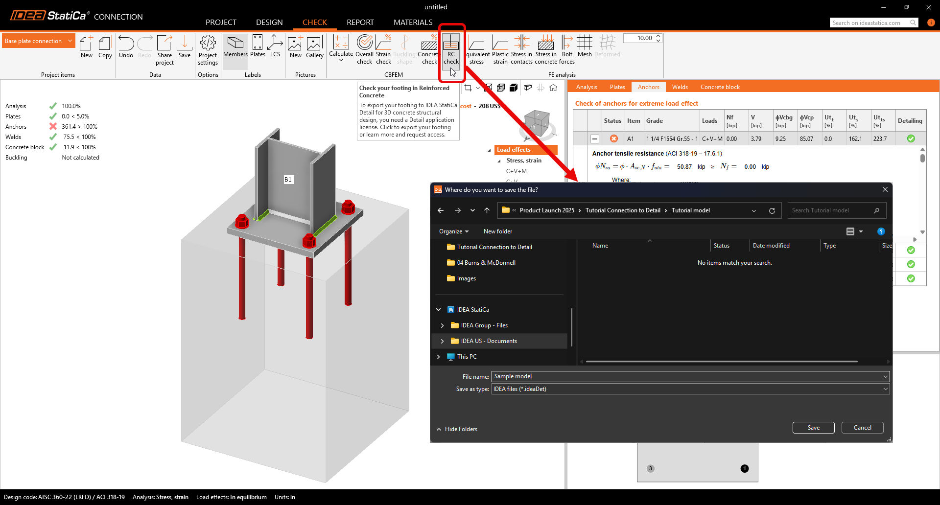
Exportul este permis doar pentru topologia de ancorare. Exportul permite transferul:
- Blocului de beton
- Ancorelor
- Plăcii de bază
- Încărcărilor
Informații suplimentare și parametri setați conform setărilor corespunzătoare din Connection:
- Transfer de forfecare (prin Ancore, Pivoți de forfecare și Frecare)
- Material
- Tip de ancorare: Post-instalate (Adezive) / Turnat in situ
- Tipul de ancorare la capăt: Șaibă/Drept/Îndoit/Cârlig/Buclă
- Coeficient de frecare
5 Proiectare
Această secțiune vă va permite să modificați Elementele, Rezemările, Încărcările și Combinațiile, precum și asamblarea armăturii.
Rezemare
Terenul are o anumită rigiditate, care trebuie luată în considerare pentru o proiectare precisă. Rezemarea de suprafață activează rigiditatea în toate cele trei direcții și este setată implicit inactivă la întindere (neliniaritate de contur).
- Vă rugăm să fiți precauți atunci când faceți ipoteze privind condițiile la limită. În cazul neliniarității, dacă momentele sunt destul de mari, rezemarea blocului de beton la întindere se poate răsturna în timpul analizei, provocând rotații mari. Aceasta poate duce la un model divergent din cauza mișcării corpului flexibil.
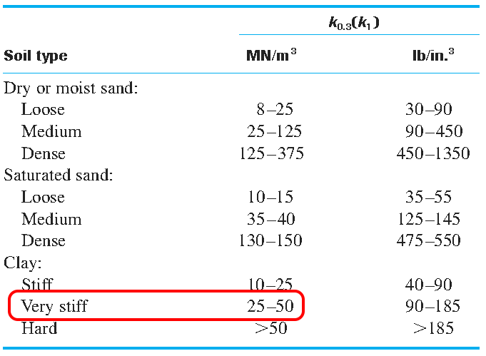
Deoarece modelul nostru este un soclu pe care barele sunt prelungite pe fundația radier, dezactivați opțiunea de rezemare numai la compresiune pentru direcția Z. Aceasta va permite armăturii continue să se interconecteze cu fundația.

Dispozitive de transfer
Ancorele sunt preluate din IDEA StatiCa Connection. Pot fi selectate două tipuri de ancore.
Ancore turnate in situ:
- Ancore pre-instalate cu aceleași proprietăți de aderență ca barele de armătură
Ancore post-instalate (Adezive):
- Ancore post-instalate (Adezive/Chimice) cu opțiunea de a personaliza rezistența la aderență pe baza rezistenței reale la aderență.

Modelarea armăturii din oțel
Setați acoperirea cu beton la 2 in, care va fi utilizată ca valoare implicită pentru armătură.

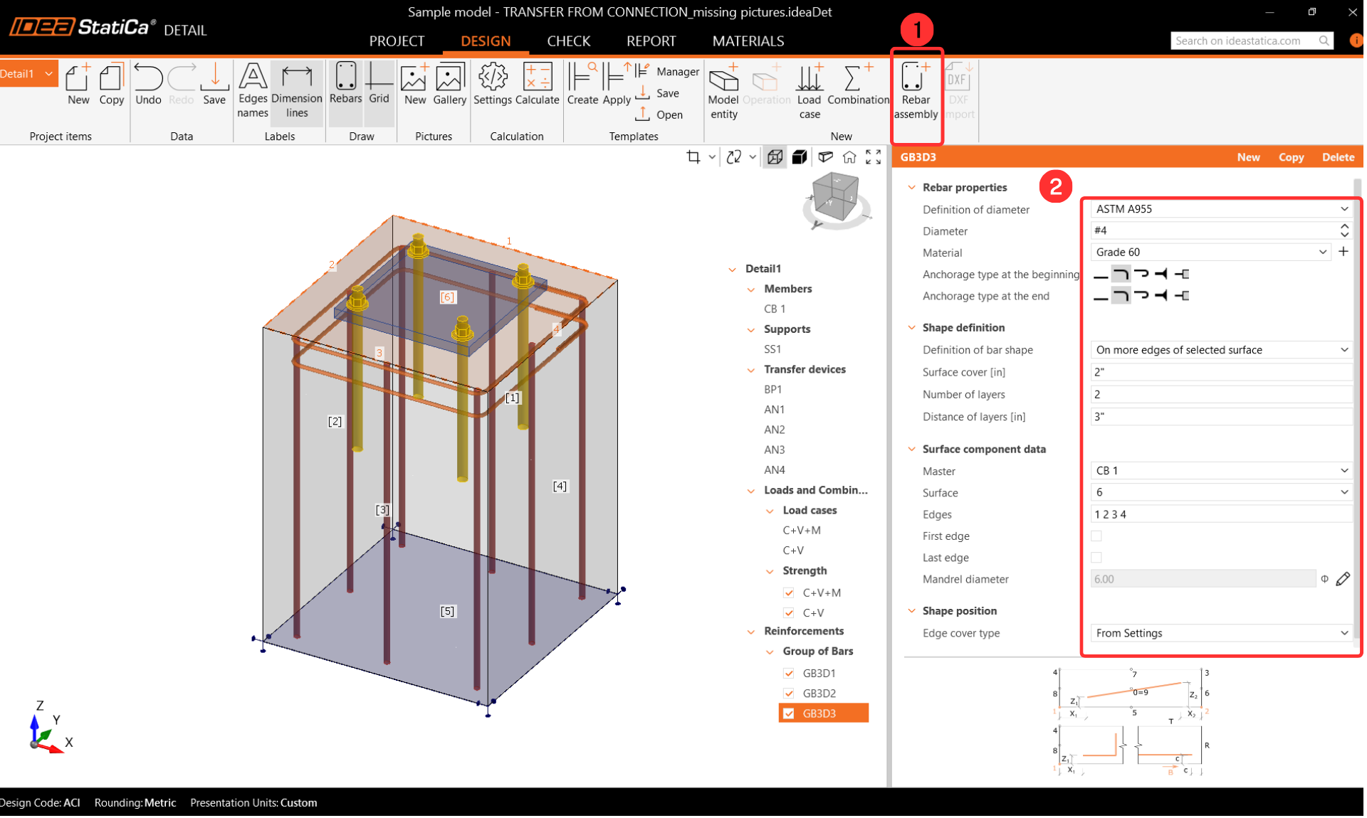
Începeți armarea soclului prin adăugarea barelor. Selectați Rebar-Assembly(1)-->Group of the bars 3D(2) și completați parametrii.

Acum trebuie să adăugăm restul barelor. Copiați operația și modificați parametrii încercuiți în roșu, așa cum este prezentat mai jos.

Pentru a adăuga etrierele inițiale, adăugați un nou grup de bare. Pașii următori furnizează datele de intrare necesare pentru parametri.
Copiați operația și modificați doar Definiția formei pentru a adăuga restul etrierilor la soclu.

Ultima parte constă în adăugarea armăturii de forfecare la soclu. În acest model, vom adăuga armătură de forfecare pentru ambele direcții.


Încărcări și combinații
Combinațiile sunt preluate din IDEA StatiCa Connection. Pentru a afla mai multe despre detaliile importului, urmați linkul - Importul ancorării din Connection în Detail.

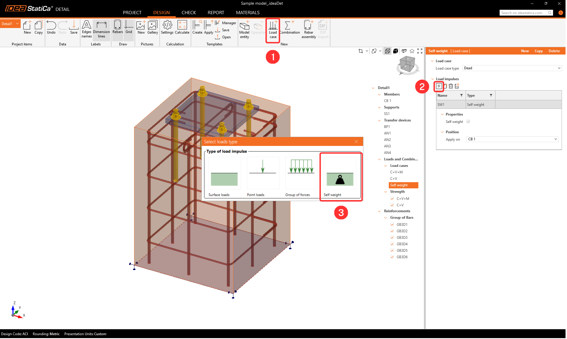
Creați un caz de încărcare Greutate proprie.
6 Verificare
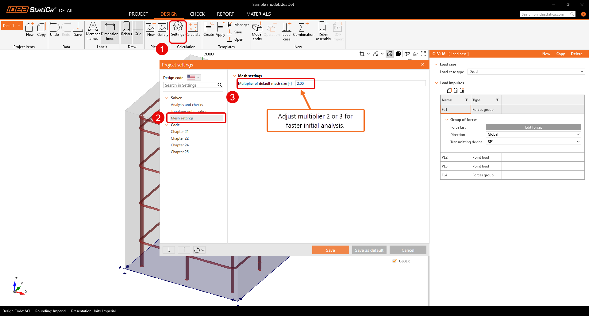
Înainte de a rula analiza, recomandăm cu tărie modificarea multiplicatorului plasei la doi sau trei pentru a accelera calculul. Acest pas nu este obligatoriu, dar poate reduce timpul de calcul și poate ajuta la detectarea eventualelor probleme de divergență. Dacă totul funcționează fără probleme și nu apar dificultăți, puteți reveni la un multiplicator de unu.

Rezultate
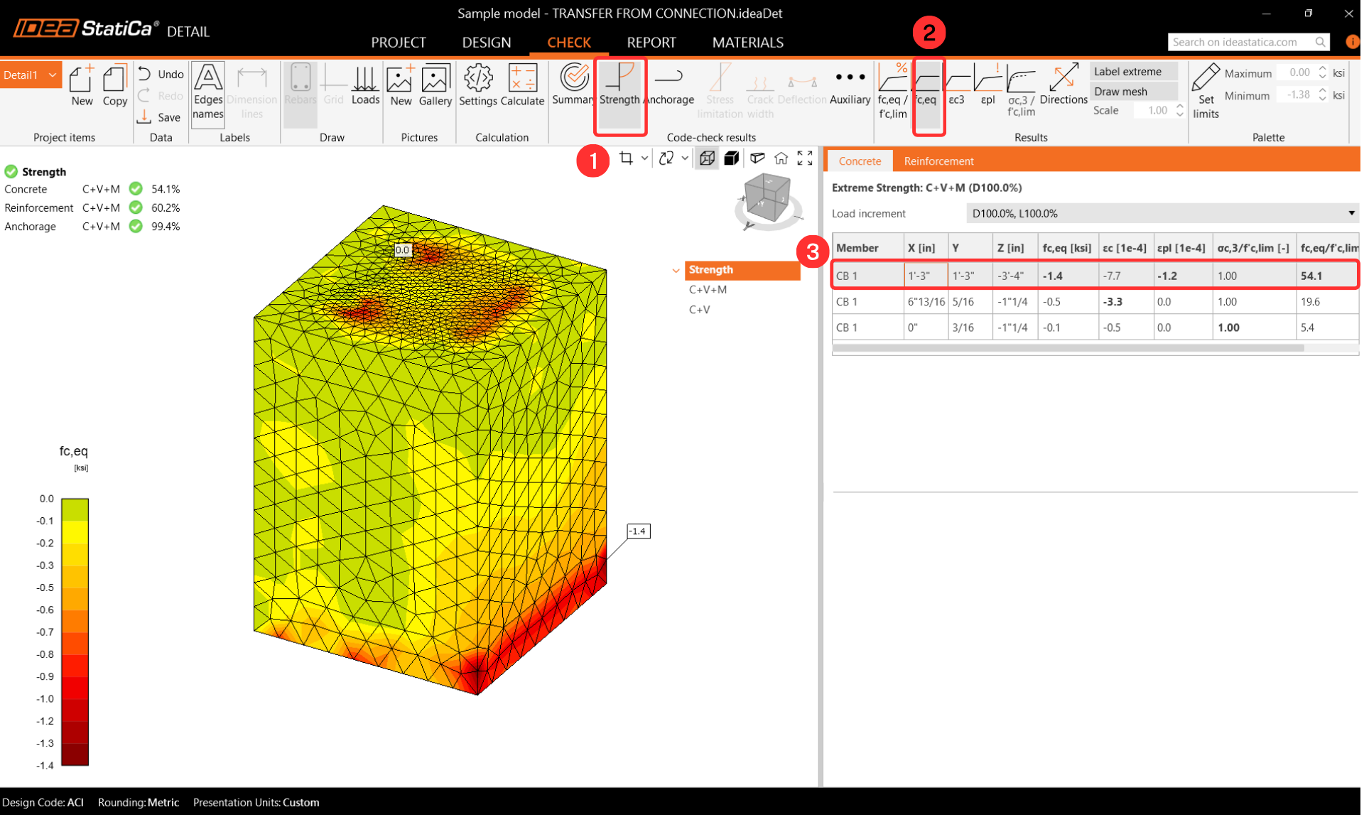
Tensiunea principală echivalentă
Tensiunea principală echivalentă (EPS) în beton este determinată pe baza comportamentului volumetric al blocului de beton. Zonele care suportă cele mai mari încărcări sunt identificate și evidențiate. Mai multe informații despre tensiunea principală echivalentă sunt incluse în acest articol din baza teoretică.
Tensiunea în bare
În timpul Verificării Armăturii, tensiunile pot fi observate pentru fiecare armătură. Puteți, de asemenea, să modificați ordinea rezultatelor pentru a vizualiza armătura cea mai solicitată. Din rezultatele reorganizate, este mai ușor să observați care ancore și armături sunt cele mai utilizate.

La afișarea gradului de utilizare a armăturii, utilizatorul poate vedea clar care armătură contribuie la transferul încărcării și la prevenirea cedării conului de beton.

Ancoraj
Verificați setările de Ancoraj și activați Forța totală în Ancore. Forțele din ancore pot varia ușor din cauza diferențelor în abordările de calcul pentru blocul de beton. Diferențele nu sunt semnificative, însă.

Deformații
Treceți la Auxiliar și activați Deformația.
Nu este necesar să se efectueze o verificare a deformației, dar este foarte recomandat să se verifice deformația după analiză pentru a se asigura că modelul nu prezintă deformații mari, rotații mari sau că niciun element finit nu este deteriorat. Aceasta va oferi o imagine de ansamblu a rezultatelor analizei și va ajuta la identificarea oricăror probleme care ar fi putut apărea în timpul analizei.

7 Raport
În final, mergeți la Previzualizare/Tipărire Raport. IDEA StatiCa oferă un raport complet personalizabil pentru tipărire sau salvare într-un format editabil.

Ați verificat întreaga proiectare a îmbinării conform AISC și ACI 318. Partea din oțel a fost verificată în IDEA StatiCa Connection, iar blocul de beton a fost verificat conform codului în IDEA StatiCa Connection și Detail.