Hegesztett kapcsolatok elemzése
A hegesztések numerikus modellekben való kezelésére több lehetőség is létezik. A nagy alakváltozások mechanikai szempontból összetettebbé teszik az elemzést, és különböző hálóleírások, különböző kinetikai és kinematikai változók, valamint alkotó modellek alkalmazhatók. Az általánosan alkalmazott 2D és 3D geometriai modellek, és ezáltal a végeselem-típusok különböző pontossági szintekre alkalmazhatók. A leggyakrabban használt anyagmodell a von Mises-féle folyási kritériumon alapuló közönséges sebességfüggetlen képlékenységi modell. Két, hegesztéseknél alkalmazott megközelítést ismertetünk. A hegesztés által okozott maradó feszültségeket és alakváltozásokat a méretezési modell nem veszi figyelembe.
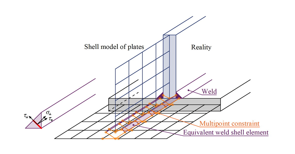
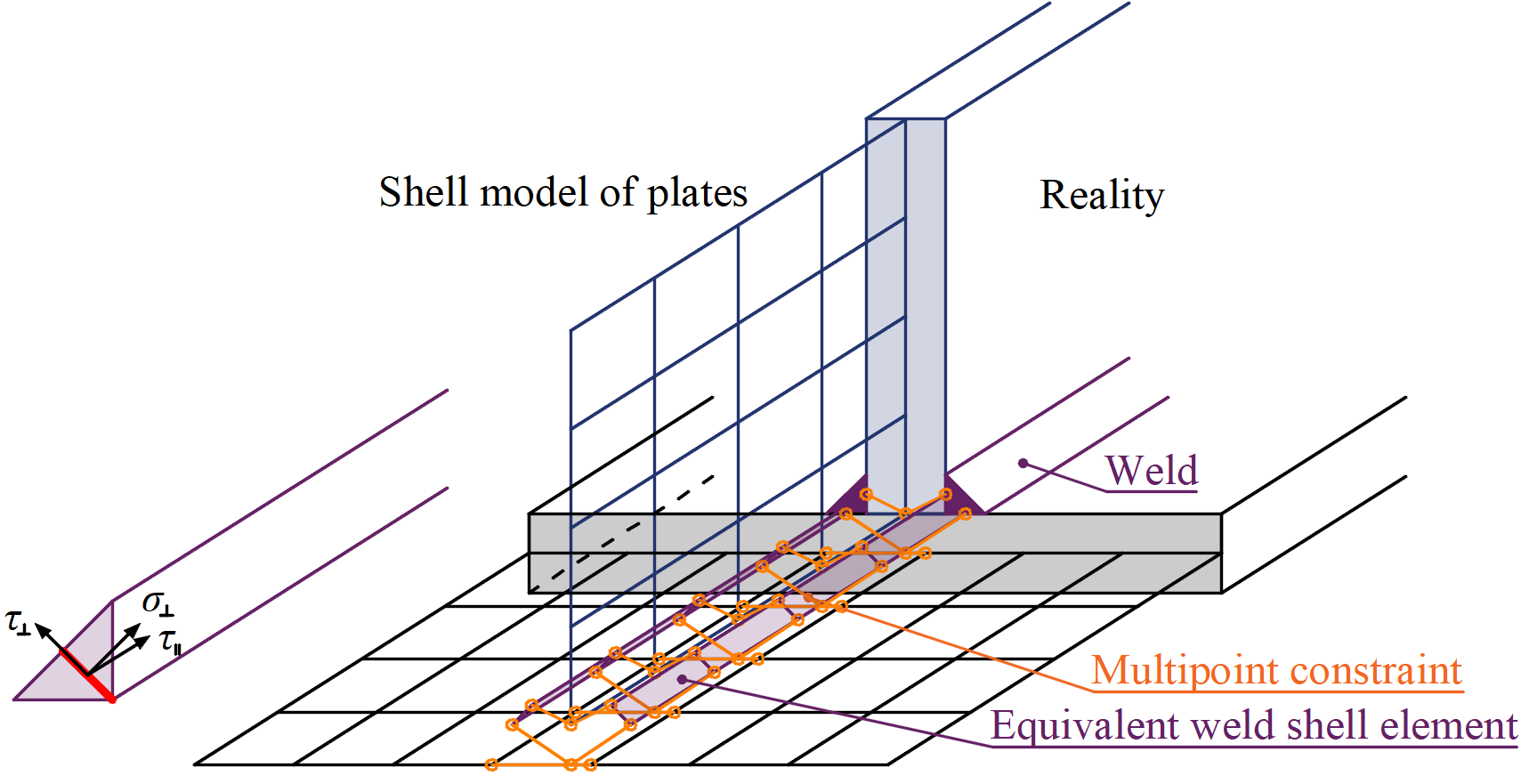
A terhelés a Lagrange-féle megfogalmazáson alapuló erő-alakváltozás kényszerfeltételeken keresztül kerül átadásra az ellentétes lemezre. A kapcsolatot többpontos kényszerfeltételnek (MPC) nevezik, és az egyik lemezél végeselem-csomópontjait a másikhoz kapcsolja. A végeselem-csomópontok nem kapcsolódnak közvetlenül egymáshoz. Ennek a megközelítésnek az előnye, hogy különböző sűrűségű hálók összekapcsolására is alkalmas. A kényszerfeltétel lehetővé teszi a kapcsolódó lemezek középvonali felületének eltolással történő modellezését, amely figyelembe veszi a valós hegesztési konfigurációt és a varrat vastagságát. A hegesztésben lévő terheléseloszlás az MPC-ből kerül levezetésre, így a feszültségek a varrat keresztmetszetében kerülnek kiszámításra. Ez fontos a hegesztés alatti lemez feszültségeloszlása és a T-csonkok modellezése szempontjából.
Képlékeny feszültség-átrendeződés a hegesztésekben
A csak többpontos kényszerfeltételeket alkalmazó modell nem veszi figyelembe a hegesztés merevségét, és a feszültségeloszlás konzervatív. A lemezélek végén, sarkokban és lekerekítéseknél megjelenő feszültségcsúcsok az egész varrat hosszán meghatározzák az ellenállást. A hatás kiküszöbölésére egy speciális rugalmas-képlékeny elemet adnak a lemezek közé. Az elem figyelembe veszi a varrat vastagságát, helyzetét és irányát. Az egyenértékű hegesztési tömör elem a megfelelő varratméretekkel kerül beillesztésre. A nemlineáris anyagelemzés kerül alkalmazásra, és az egyenértékű hegesztési tömör elemben a rugalmas-képlékeny viselkedés kerül meghatározásra. A képlékenységi állapotot a varrat keresztmetszetében lévő feszültségek szabályozzák. A feszültségcsúcsok a varrat hosszának nagyobb részén átrendeződnek.
A hegesztések rugalmas-képlékeny modellje valós feszültségértékeket ad, és nincs szükség a feszültség átlagolására vagy interpolálására. A legjobban igénybevett varratelem számított értékeit közvetlenül a varrat komponens ellenőrzéséhez használják. Így nincs szükség a többirányú hegesztések, merevítetlen övekhez készített hegesztések vagy hosszú hegesztések ellenállásának csökkentésére.
Kényszerfeltétel a varratelem és a hálócsomópontok között
Az általános hegesztések, képlékeny átrendeződés alkalmazása esetén, folyamatos, részleges és szakaszos kivitelűre állíthatók be. A folyamatos hegesztések az él teljes hosszán végigfutnak, a részleges lehetővé teszi a felhasználók számára, hogy az él mindkét oldalán eltolásokat állítsanak be, a szakaszos hegesztések pedig további beállításként meghatározott hosszal és hézaggal adhatók meg.