A szerény talplemez kapcsolat tervezése
Az egyszerű toldott kapcsolatról szóló első bejegyzésem folytatásaként ebben a bejegyzésben a szerény talplemezről fogok beszélni. Ez a kapcsolattípus volt az első, amelyet valaha terveztem, és akkoriban valóban nagyon egyszerű volt. Ha kíváncsi vagy, a toldott kapcsolat szorosan a második helyen végzett!
Ismét sok minden megváltozott az évek során – nem utolsósorban a szabványok. Az épületek összetettebbé váltak – mind megjelenésükben, mind a sikeres tervezésükhöz szükséges szakterületek számában. Ahogy az épületek és szerkezeti felépítésük egyre összetettebbé válik, a mérnökök egyre több időt töltenek az általuk generált összetett kapcsolatokkal. Az IDEA StatiCa segít enyhíteni ezeket a bonyolultságokat egy könnyen érthető felületen, amely hatékony, pontos, szabványellenőrzött kapcsolatokat hoz létre.
A szerény talplemez valószínűleg az egyik utolsó kapcsolat, amelyet megterveznek, de szó szerint az első acélelem, amelyre egy projektben szükség van. Egyes tervek építészeti szempontokat is figyelembe vesznek, a legtöbb tisztán funkcionális alapon készül, ahol a forma másodlagos. Az IDEA StatiCa rendelkezik azokkal az eszközökkel, amelyekkel szinte bármilyen elképzelhető konfiguráció modellezhető, elemezhető és ellenőrizhető.
A Támogatási Központunkban végzett gyors keresés számos projektet mutat, amelyeket ügyfeleink felhasználhatnak az IDEA StatiCa megismeréséhez:
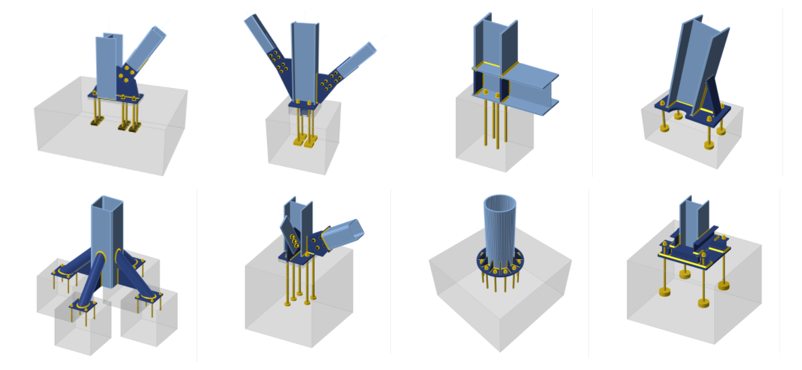
Mindezek a példák projektfájllal érkeznek, és az online Viewerben is megtekinthetők – szóval mire vársz? Ezeket a projekteket a Támogatási Központunkban találod.
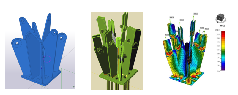
Nemcsak ezeket a viszonylag egyszerű talplemezeket tudjuk megtervezni, hanem az IDEA StatiCa-t a világ vezető mérnökei és gyártói is használták néhány nagyon összetett kapcsolat tervezéséhez:
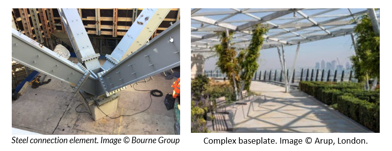
Mindkét esetben az IDEA StatiCa lehetővé tette a mérnökök számára, hogy elegánsan és magabiztosan tervezzék meg az összetett talplemez kapcsolatot.
Mi alkotja a talplemez kapcsolatot?
Nyilvánvalóan maga a talplemez. De milyen vastag? Milyen anyagból?
Ezután egy vagy több megtámasztandó szerkezeti elem következik.
Milyen erők vesznek részt, és hol hatnak?
Végül az alapozást és a horgonyzási rendszert kell figyelembe venni. Milyen vastag? Milyen minőségű? Milyen típusú horgony és milyen átmérőjű?
Az IDEA StatiCa ezt többféleképpen közelítheti meg:
- A kapcsolat felépítése lépésről lépésre az IDEA StatiCa alkalmazásban
- BIM kapcsolat használata egy elemzési alkalmazásból
- BIM kapcsolat használata egy modellező alkalmazásból (eredményekkel vagy anélkül)
- Az új Checkbot funkció használata egy geometriai modell és elemzési eredmények kombinálásához
Kétségtelen, hogy mindenkinek megfelelő megközelítést kínálunk, attól függően, hogy mennyire kívánják integrálni az általános tervezést.
Kapcsolat tervezése lépésről lépésre
A lépésről lépésre haladó megközelítés a talplemezből kiindulva felfelé és lefelé építi fel a kapcsolatot. A felhasználó hozzáadja a szerkezeti elemeket, elhelyezi őket, és létrehozza az ezekre ható teherhatásokat. További műveletek határozzák meg a talplemezét (és a betonalapozást), valamint számos egyéb speciális műveletet, mint például csomólemezek stb. Ez a legtöbb időt igénylő (de gyakran kielégítő) megközelítés. Ez a megközelítés nagyobb kockázatot is hordoz, amikor egy vagy több forrásból az adatokat az IDEA StatiCa-ba visszük át.
BIM kapcsolat elemzési szoftverből
Az elemzési alkalmazásból származó BIM kapcsolat használata lehetővé teszi, hogy a szerkezeti elemek és a teherhatások átkerüljenek az IDEA StatiCa-ba az új Checkbot alkalmazáson (vagy a régi Code-check manageren) keresztül. Ez a megközelítés még mindig megköveteli, hogy a további komponenseket manuálisan modellezzék az IDEA StatiCa-ban, de kisebb kockázatot hordoz.
BIM kapcsolat modellező szoftverből
Ha az előnyben részesített útvonal egy modellező alkalmazásból, például Revitből, Advance Steelből vagy Tekla Structuresből indul ki, akkor a kapcsolat komponensei az új Checkbot alkalmazáson (vagy a régi Code-check manageren) keresztül kerülnek replikálásra az IDEA StatiCa-ban. Ez a megközelítés azt feltételezi, hogy a teherhatásokat vagy manuálisan kell megadni, vagy automatikusan, ha a modellező szoftver lehetővé teszi, és hozzáfér a beágyazott vagy csatolt eredményekhez.
Mi történik, ha szeretnéd felhasználni a fent leírt koncepciókat, de nincsenek olyan alkalmazásaid, amelyek egymással kommunikálnak, de az IDEA StatiCa-val igen? Itt lép be a képbe a Checkbot alkalmazásunk új funkciója, amely lehetővé teszi egy geometriai modell és egy elemzési modell kombinálását a teherhatások két Checkbot projektből való importálásával.
Mik a tényleges tervezési szempontok?
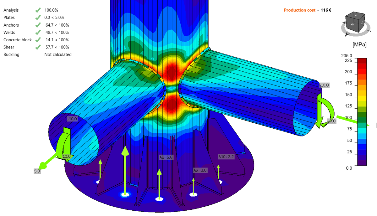
A talplemeznek megfelelő méretűnek, merevségűnek és szilárdságúnak kell lennie ahhoz, hogy az oszlopból érkező tengelyes nyomóerőt az ágyazóanyagon keresztül az alapozásra tudja átvinni, anélkül, hogy meghaladná az alapozás helyi nyomási ellenállását.
A leggyakoribb az egyszerű négyzet vagy téglalap alakú talplemez. Ez könnyen beszerezhető és kevés hulladékkal gyártható. Összehasonlítva egy négyzetből kivágott kör alakú talplemezzel, ez biztosan igaz. De melyik lenne esztétikailag vonzóbb egy kör keresztmetszetű üreges oszlop alátámasztásakor?
A horgonyzási rendszernek biztonságosan kell átvinnie az erőket az alapozásra. Ha egy normál csavaros kialakítás nem elegendő, akkor nyírófog alkalmazása jöhet szóba. Hogyan hatnak ezek kölcsön a rögzítőcsavarokkal és az alapozásban esetlegesen elhelyezett vasalással? Ez az a terület, ahol a BIM kiemelkedik – több szakterület integrálásának és koordinálásának képességével.
Ha elolvasod a gyakorlati irányelveket, azok az oszlop kiterjedésén túl extra 100 mm (4") ráhagyásról beszélnek. Azt is javasolják, hogy a méreteket a legközelebbi 50 mm-re (2") kerekítsük fel. Ez nem hangzik túl hatékonynak – kell lennie egy jobb módszernek! Nos, van: IDEA StatiCa Connection.

Egy egyszerű tervezési megközelítés a következőkből áll:
- Szükséges terület ellenőrzése
- Hatékony terület ellenőrzése
- Lemezvastagság ellenőrzése
- Hegesztés ellenőrzése
Ez az egyszerű szerkezetű, tengelyes nyomást és nyírást felvevő oszlopokra vonatkozik. Ha az oszlopba merevítő szerkezeti elem csatlakozik, vagy nyomatékot vesz fel, akkor ezek az ellenőrzések összetettebbé válnak és több időt igényelnek. Ez a 80/20 szabály klasszikus példája, ahol a kapcsolatok 80%-a az idő 20%-át veszi igénybe, és a kapcsolatok 20%-a az idő 80%-át veszi igénybe.
Ha a tervezésbe eleganciát és hatékonyságot is beviszünk, akkor a szerény talplemez már nem is olyan szerény. Ennek nagyszerű példája az, ahogyan a Wade Design Engineers az IDEA StatiCa-t használta egy dubaji feszített szövetszerkezet bonyolult, építészetileg meghatározott talplemezének ellenőrzésére.
A vázlatoktól a modellezésen át az elemzésig és a szabványellenőrzésig:
Egy egyszerűsített munkafolyamatot alkalmazva, amely a Tekla Structures BIM kapcsolatát használta. Ezek azok a munkafolyamatok, amelyek segítik a mérnököt mindennapi feladataiban. A modellek több formátumban való átvételének és az IDEA StatiCa-ba való kombinálásának képessége csökkenti az időt és a kockázatot. Ez lehetővé teszi a mérnökök számára, hogy arra koncentráljanak, amire szükségük van, és több időt fordítsanak a kapcsolat fejlesztésére, a változatok és a kapcsolódó költségek feltárására. A jelenlegi helyzetben mindannyiunknak meg kell felelni a kihívásnak!
A Marshall Building projektről itt olvashat bővebben, a dubaji projekt esettanulmánya pedig itt található.
Az IDEA StatiCa próbaverzióját itt töltheti le, és ezeket az oktatóanyagokat használhatja a kezdéshez. Ha mélyebb tudásra vágyik, itt található a CBFEM és az IDEA StatiCa elméleti háttere.
Jó utat!