Verificación normativa de bloques de hormigón (AISC)
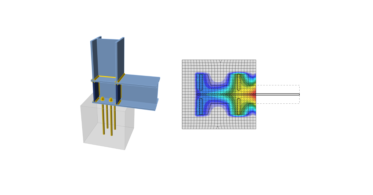
El hormigón bajo la placa base se simula mediante el subsuelo de Winkler con rigidez uniforme, que proporciona las tensiones de contacto. La tensión media en el área cargada en contacto con la placa base se utiliza para la verificación a compresión.
Hormigón en compresión
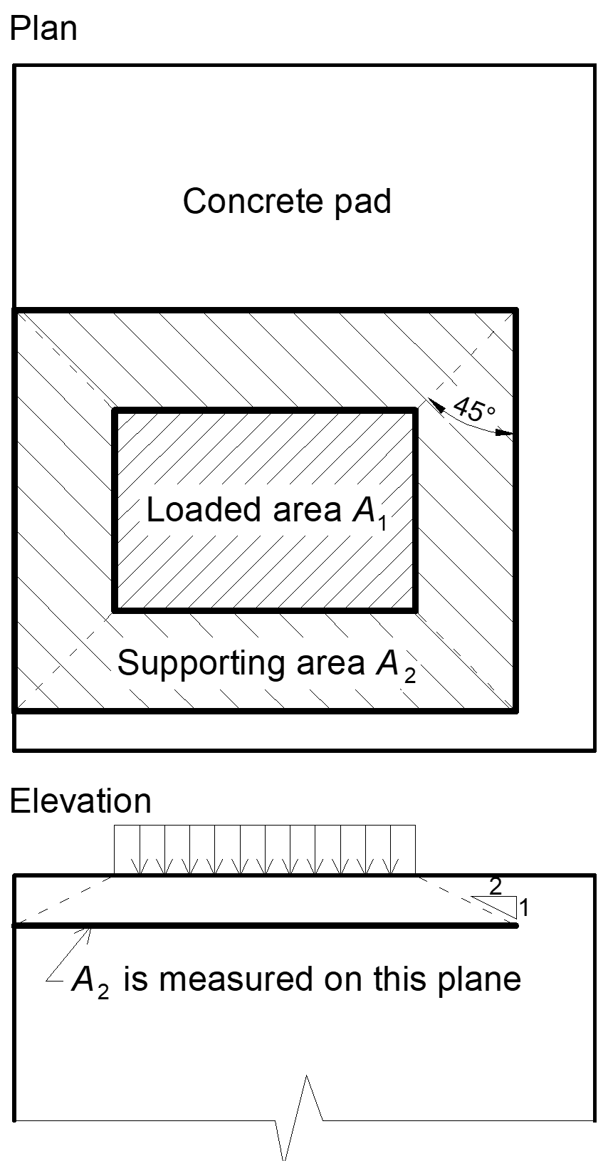
Diseño del hormigón La resistencia de apoyo en compresión se diseña según AISC 360-16, Sección J8. Cuando la superficie de apoyo del hormigón es mayor que la placa base, la resistencia de apoyo de cálculo se define como
\[ f_{p(max)}=0.85 f_c \sqrt{\frac{A_2}{A_1}} \le 1.7 f'_c \]
donde:
- f'c – resistencia a compresión del hormigón
- A1 – área de la placa base en contacto con la superficie de hormigón (área de la superficie superior del tronco de pirámide)
- A2 – superficie de apoyo del hormigón (área inferior geométricamente similar del tronco de pirámide con pendientes de 1 vertical a 2 horizontal)
La verificación del hormigón en el apoyo es la siguiente
σ ≤ ϕc fp(max) para LRFD
σ ≤ fp(max) / Ωc para ASD
donde:
- σ – tensión media de compresión bajo la placa base
- ϕc = 0.65 – factor de resistencia para el hormigón
- Ωc = 2.31 – factor de seguridad para el hormigón
Transferencia de fuerzas cortantes
Las cargas de cortante pueden transferirse mediante una de estas opciones:
- Llave de corte,
- Fricción,
- Pernos de anclaje.
Llave de corte
Solo está disponible LRFD. La carga de cortante se transfiere mediante la llave de corte. Son necesarias las verificaciones del hormigón en apoyo y, a menos que se proporcione armadura para desarrollar la resistencia requerida, las verificaciones de rotura del hormigón.
La capacidad de apoyo de la llave de corte frente al hormigón se determina según ACI 349-01 – B.4.5 y ACI 349-01 RB11 como:
ϕPbr = ϕ 1.3 f'c A1 + ϕ Kc (Ny – Pa)
donde:
- ϕ = 0.7 – factor de reducción de resistencia para apoyo sobre hormigón según ACI 349
- f'c – resistencia a compresión del hormigón
- A1 – área proyectada de la llave de corte embebida en la dirección de la fuerza, excluyendo la parte de la llave en contacto con la lechada sobre el elemento de hormigón
- Kc = 1.6 – coeficiente de confinamiento
- Ny = n Ase Fy – resistencia a la fluencia de los anclajes traccionados
- Pa – carga axial exterior
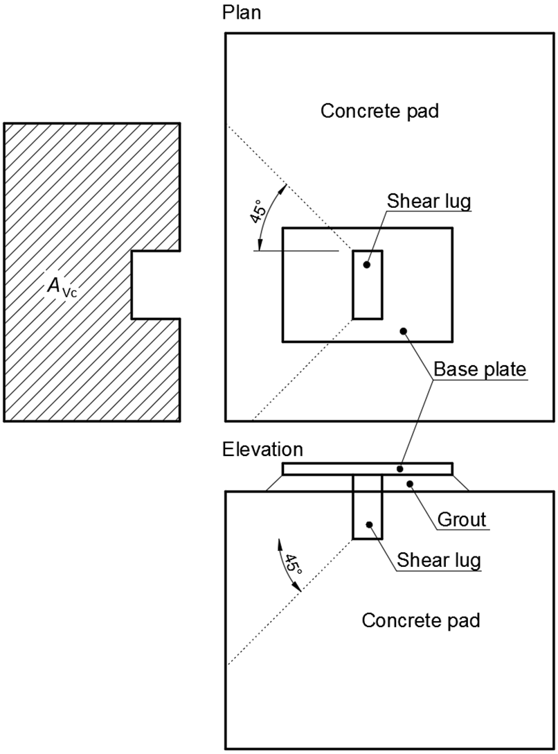
La resistencia a la rotura del hormigón de la llave de corte según ACI 349 – B11 es:
\[ \phi V_{cb} = A_{Vc} 4 \phi \sqrt{f'_c} \]
donde:
- ϕ = 0.85 – factor de reducción de resistencia a cortante según ACI 349
- AVc – área de tensión efectiva definida proyectando un plano a 45° desde los bordes de apoyo de la llave de corte hasta la superficie libre en la dirección de la carga de cortante. El área de apoyo de la llave de corte queda excluida del área proyectada
Si la resistencia a la rotura del hormigón en la configuración normativa está desactivada, se proporciona al usuario la fuerza que debe transferirse mediante hormigón armado.
Fricción
La carga de cortante se transfiere mediante fricción. La resistencia al cortante se determina como:
ϕc Vr = ϕc μ C (LRFD)
Vr / Ωc =μ C / Ωc (ASD)
donde:
- ϕc = 0.65 – factor de resistencia (LRFD)
- Ωc = 2.31 – factor de seguridad (ASD)
- μ = 0.4 – coeficiente de fricción entre la placa base y el hormigón (valor recomendado 0.4 en la Guía de Diseño AISC 7 – 9.2 y ACI 349 – B.6.1.4, editable en la configuración normativa)
- C – fuerza de compresión
Pernos de anclaje
Si la carga de cortante se transfiere únicamente mediante pernos de anclaje, la fuerza cortante que actúa sobre cada anclaje se determina mediante el Método de los Elementos Finitos y los pernos de anclaje se verifican según ACI 318-14 tal como se describe en los capítulos siguientes.