Descripción
El objetivo de este estudio es la verificación de la unión de momento en alero de pórtico atornillado, como se muestra en la Fig. 9.2.1. La viga inclinada se atornilla mediante placa de testa en el ala de la columna. La columna está rigidizada con dos rigidizadores horizontales a la altura de las alas de la viga. Las placas comprimidas, p. ej. los rigidizadores horizontales de la columna, el panel de alma a cortante o a compresión, y el ala comprimida de la viga, se diseñan como sección transversal de clase 3. La viga horizontal tiene 6 m de longitud y está cargada por una carga continua en toda su longitud.

Fig. 9.2.1 Unión de momento en alero de pórtico atornillado
Modelo analítico
Se examinan ocho componentes: soldadura en ángulo, panel de alma a cortante, alma de columna a compresión transversal, alma de columna a tracción transversal, ala de viga a compresión y tracción, ala de columna a flexión, placa de testa a flexión y tornillos. Todos los componentes se diseñan según EN 1993-1-8:2005. Las cargas de cálculo de los componentes dependen de su posición. El panel de alma a cortante se carga con las cargas de cálculo en el eje vertical de la columna. Los demás componentes se cargan con las cargas de cálculo reducidas en el ala de la columna a la que se conecta la viga horizontal.
Soldadura en ángulo
La soldadura rodea toda la sección transversal de la viga. El espesor de la soldadura en las alas puede diferir del espesor de la soldadura en el alma. La fuerza cortante vertical es transferida únicamente por las soldaduras del alma y se considera una distribución plástica de tensiones. El momento flector es transferido por toda la forma de la soldadura y se considera una distribución elástica de tensiones. Se considera el ancho efectivo de soldadura en función de la rigidez horizontal de la columna (debido a la flexión del ala de columna no rigidizada). El diseño de la soldadura se realiza según EN 1993-1-8:2005, Cl. 4.5.3.2(6). La comprobación se lleva a cabo en dos puntos principales: en el borde superior o inferior del ala (tensión máxima de flexión) y en la intersección del ala y el alma (combinación de tensiones de fuerza cortante y momento flector).
Panel de alma a cortante
El espesor del alma de la columna se diseña como máximo de clase tercera; véase EN 1993-1-8:2005, Cl. 6.2.6.1(1). Se consideran dos contribuciones a la capacidad de carga: la resistencia de la pared de la columna a cortante y la contribución del comportamiento de pórtico de las alas de la columna y los rigidizadores horizontales; véase EN 1993-1-8:2005, Cl. 6.2.6.1 (6.7 y 6.8).
Alma de columna a compresión o tracción transversal
Se considera el efecto de la interacción de la carga cortante; véase EN 1993-1-8:2005, Cl. 6.2.6.2 y Tab. 6.3. Se considera la influencia de la tensión longitudinal en la pared de la columna; véase EN 1993-1-8:2005, Cl. 6.2.6.2(2). Los rigidizadores horizontales evitan el pandeo y se incluyen en la capacidad de carga de este componente con el área efectiva.
Ala de viga a compresión
La viga horizontal se diseña como máximo de clase tercera.
Ala de columna o placa de testa a flexión
Se consideran las longitudes efectivas para fallos circulares y no circulares según EN 1993-1-8:2005, Cl. 6.2.6. Se consideran tres modos de colapso según EN 1993-1-8:2005, Cl. 6.2.4.1.
Tornillos
Los tornillos se diseñan según EN 1993-1-8:2005, Cl. 3.6.1. La resistencia de cálculo considera la resistencia al punzonamiento y la rotura del tornillo.
Modelo numérico de diseño
El stub-T se modela mediante elementos laminares de 4 nodos como se describe en el Capítulo 3 y se resume a continuación. Cada nodo tiene 6 grados de libertad. Las deformaciones del elemento consisten en contribuciones de membrana y flexión. El estado del material elastoplástico no lineal se investiga en cada capa del punto de integración. La comprobación se basa en la deformación máxima dada según EN 1993-1-5:2006 con un valor del 5 %. Los tornillos se dividen en tres subcomponentes. El primero es el vástago del tornillo, que se modela como un muelle no lineal y solo trabaja a tracción. El segundo subcomponente transmite la fuerza de tracción a las alas. El tercer subcomponente resuelve la transmisión del cortante.
Comportamiento global
Se realizó una comparación del comportamiento global de la unión, descrito mediante diagramas momento-giro para ambos procedimientos de diseño mencionados anteriormente. La atención se centró en las características principales del diagrama momento-giro: rigidez inicial, resistencia de cálculo y capacidad de deformación. La viga IPE 330 se conecta a la columna HEB 300 mediante placa de testa extendida con 5 filas de tornillos M24 8.8. Los resultados de ambos procedimientos de diseño se muestran en el gráfico de la Fig. 9.2.2 y en la Tab. 9.2.1. El MC generalmente proporciona una rigidez inicial mayor en comparación con el CBFEM. El CBFEM proporciona una resistencia de cálculo ligeramente mayor en comparación con el MC en todos los casos, como se muestra en el Capítulo 9.2.5. La diferencia es de hasta un 10%. También se compara la capacidad de deformación. La capacidad de deformación se calculó según (Beg et al. 2004) porque el EC3 proporciona una base limitada para la capacidad de deformación de las uniones con placa de testa.

Fig. 9.2.2 Diagrama momento-giro
Tab. 9.2.1 Resumen del comportamiento global
| MC | CBFEM | MC/CBFEM | ||
| Rigidez inicial | [kNm/rad] | 67400 | 112000 | 0,60 |
| Resistencia de cálculo | [kNm] | 204 | 199 | 0,98 |
| Capacidad de deformación | [mrad] | 242 | 47 | 5,14 |
Verificación de la resistencia
En el siguiente paso, la resistencia de cálculo calculada por CBFEM se comparó con los resultados del método de componentes. La comparación se centró en la resistencia y también en el componente crítico. El estudio se realizó para el parámetro de sección transversal de la columna. La viga IPE 330 se conecta a la columna mediante placa de testa extendida con 5 filas de tornillos. Se utilizan tornillos M24 8.8. Las dimensiones de la placa de testa P15 con distancias al borde y separaciones de tornillos en milímetros son: altura 450 (50-103-75-75-75-73) y anchura 200 (50-100-50). El borde exterior del ala superior está a 91 mm del borde de la placa de testa. Las alas de la viga se conectan a la placa de testa con soldaduras de garganta 8 mm. El alma de la viga se conecta con una garganta de soldadura de 5 mm. La columna está rigidizada con rigidizadores horizontales frente a las alas de la viga. Los rigidizadores tienen 15 mm de espesor y su anchura corresponde a la anchura de la columna. El espesor del rigidizador de la placa de testa es de 10 mm y su anchura es de 90 mm. Los resultados se muestran en la Tab. 9.2.2 y la Fig. 9.2.3.
Tab. 9.2.2 Resistencia de cálculo para el parámetro – perfil de columna
| Sección transversal de columna | MC | CBFEM | MC/ CBFEM | ||
| Resistencia | Componente | Resistencia | Componente | ||
| [kNm] | [kNm] | ||||
| HEB 200 | 107 | Alma de columna a cortante | 106 | Alma de columna a cortante | 1,01 |
| HEB 220 | 121 | Alma de columna a cortante | 136 | Alma de columna a cortante | 0,89 |
| HEB 240 | 143 | Alma de columna a cortante | 155 | Alma de columna a cortante | 0,92 |
| HEB 260 | 160 | Alma de columna a cortante | 169 | Alma de columna a cortante | 0,95 |
| HEB 280 | 176 | Alma de columna a cortante | 187 | Alma de columna a cortante | 0,94 |
| HEB 300 | 204 | Alma de columna a cortante | 199 | Ala de viga a tracción/compresión | 0,98 |
| HEB 320 | 222 | Alma de columna a cortante | 225 | Ala de viga a tracción/compresión | 0,99 |
| HEB 340 | 226 | Ala de viga a tracción/compresión | 242 | Ala de viga a tracción/compresión | 0,93 |
| HEB 360 | 229 | Ala de viga a tracción/compresión | 239 | Ala de viga a tracción/compresión | 0,96 |
| HEB 400 | 234 | Ala de viga a tracción/compresión | 253 | Ala de viga a tracción/compresión | 0,92 |
| HEB 450 | 241 | Ala de viga a tracción/compresión | 260 | Ala de viga a tracción/compresión | 0,93 |
| HEB 500 | 248 | Ala de viga a tracción/compresión | 268 | Ala de viga a tracción/compresión | 0,93 |
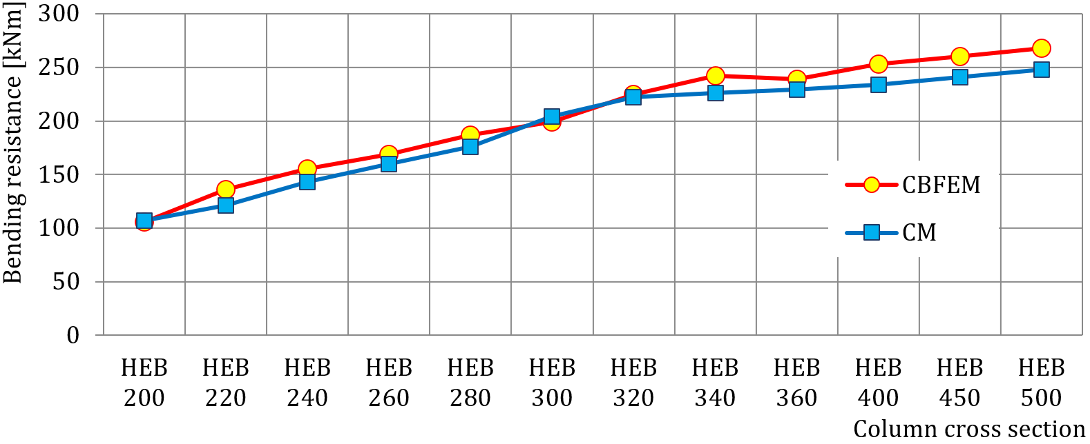
Fig. 9.2.3 Resistencia de cálculo en función de la sección transversal de la columna
Para ilustrar la precisión del modelo CBFEM, los resultados de los estudios paramétricos se resumen en el gráfico que compara las resistencias predichas por CBFEM y por MC; véase la Fig. 9.2.4. Los resultados muestran que el CBFEM proporciona una resistencia de cálculo ligeramente mayor en comparación con el MC en casi todos los casos. La diferencia entre ambos métodos es de hasta un 10%.

Fig. 9.2.4 Verificación del CBFEM respecto al MC
Ejemplo de referencia
Datos de entrada
- Acero S235
- Viga IPE 330
- Columna HEB 300
- Altura de la placa de testa hp = 450 (50-103-75-75-75-73) mm
- Anchura de la placa de testa bp = 200 (50-100-50) mm
- Placa de testa P15
- Rigidizadores de columna de 15 mm de espesor y 300 mm de anchura
- Rigidizador de placa de testa de 10 mm de espesor, 90 mm de anchura y canto, chaflanes de 20 mm
- Garganta de soldadura del ala af = 8 mm
- Garganta de soldadura del alma y del rigidizador de placa de testa aw = 5 mm
- Tornillos M24 8.8
Resultados
- Resistencia de cálculo a flexión MRd = 206 kNm
- Fuerza cortante vertical correspondiente VEd= –206 kN
- Modo de colapso: plastificación del rigidizador de viga en el ala superior
- Utilización de los tornillos 90,2 %
- Utilización de las soldaduras 99,0 %