Bemessung eines vorgespannten Verbundquerschnitts in RCS
Erstellen eines neuen Projekts
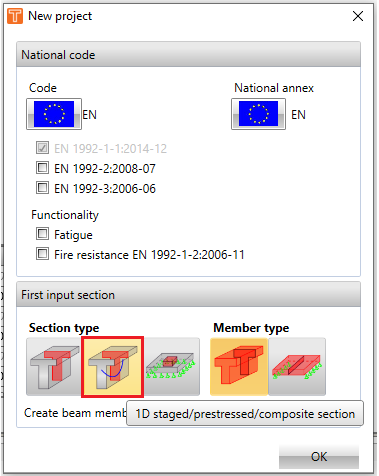
Zunächst ist es erforderlich, ein neues Projekt als ein 1D-Bauteil mit Bauphasen/Vorspannung/Verbund einzurichten.
Bemessungsbauteil
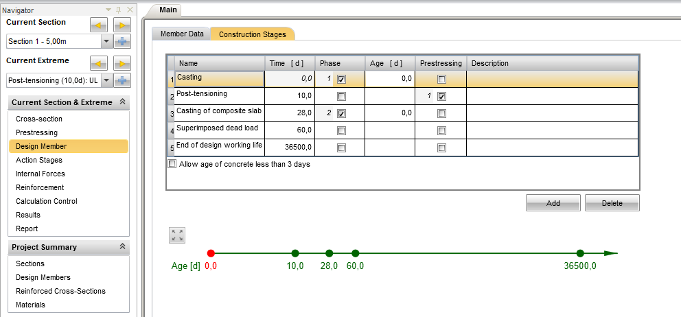
Nach der Definition der Querschnittsgeometrie und der Bewehrungsanordnung wird die Zeitachse im Tab Bauphasen festgelegt. Alle wichtigen Zeitpunkte während der Konstruktion werden definiert (z. B. Betonieren des ersten Teils des Querschnitts des Fertigteilträgers, Vorspannen, Betonieren des zweiten Teils des Querschnitts der Verbundplatte, aufgebrachte Eigenlasten und der Zeitpunkt der Bemessungsnutzungsdauer). Die definierten Bauphasen werden automatisch im Tab Lastphasen übernommen.
Lastphasen
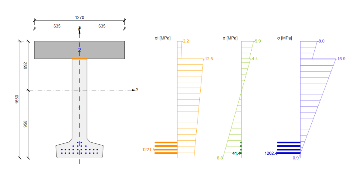
Aus der Sicht des Normnachweises von Verbundquerschnitten ist der Tab „Lastphasen" am wichtigsten. Die Definition des Ausgangsspannungszustands des Querschnitts, der durch die zeitabhängige Analyse (TDA) berechnet wird, ist entscheidend, da die Spannungsunstetigkeitsstelle (die Ebene der Dehnungsverschiebung) an der Grenzfläche zwischen zwei verschiedenen Betonen den Versagensmechanismus im Grenzzustand bestimmen kann.
Ausgangszustand des Querschnitts
Der Ausgangszustand des Verbundquerschnitts wird in der Tabelle "Schnittgrößen in Querschnittskomponenten" festgelegt. Es können zwei Optionen zur Definition des Ausgangszustands gewählt werden – Schnittgrößen und Dehnungsebenen. Es ist wesentlich einfacher, die aus der TDA berechneten Schnittgrößen aus Drittanbieter-Software (Midas, SCIA, etc.) zu definieren.
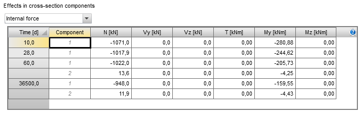
Die Tabelle „Schnittgrößen in Querschnittskomponenten" enthält die Schnittgrößen als Summe aus:
- Allen ständigen Lasten, die in der betrachteten Bauphase wirken
- Der Gesamtwirkung der Vorspannung (die primären und sekundären Wirkungen von verbundenen und nicht verbundenen internen Spanngliedern, die primären und sekundären Wirkungen von externen Spanngliedern)
- Rheologie (Kriechen, Schwinden)
Die meisten Drittanbieter-Programme (Midas, SCIA, etc.) stellen die Schnittgrößen jedes Teils des Verbundquerschnitts bezogen auf den Schwerpunkt des betrachteten Querschnittsteils dar (zum Beispiel wird das Biegemoment im Fertigteilträger auf den Schwerpunkt des Fertigteilträgers Cg,1 bezogen). Die RCS-Anwendung bezieht die Schnittgrößen auf den Schwerpunkt des tatsächlichen Querschnitts (Schaltfläche „Aktuell" im Menüband) oder den Schwerpunkt des endgültigen Verbundquerschnitts Cg,i (Schaltfläche „Gesamt" im Menüband). Die Umrechnung der aus Drittanbieter-Software erhaltenen Schnittgrößen für RCS kann gemäß den folgenden Formeln durchgeführt werden:
\[N_{i}^{T} = N_{i}\]
\[M_{i}^{T} = M_{i}-N_{i}\times e_{i}\]
NiT . . . . die Normalkraft im betrachteten Teil des Verbundquerschnitts, umgerechnet auf den Schwerpunkt des idealisierten endgültigen Verbundquerschnitts
MiT . . . . das Biegemoment im betrachteten Teil des Verbundquerschnitts, umgerechnet auf den Schwerpunkt des idealisierten endgültigen Verbundquerschnitts
Ni . . . . die Normalkraft im betrachteten Teil des Verbundquerschnitts, bezogen auf den Schwerpunkt des betrachteten Querschnittsteils
Mi . . . . das Biegemoment im betrachteten Teil des Verbundquerschnitts, bezogen auf den Schwerpunkt des betrachteten Querschnittsteils
Hinweis: Die Einhaltung der in der nachfolgenden Abbildung dargestellten Vorzeichenkonvention ist für die Umrechnung der Schnittgrößen wichtig.
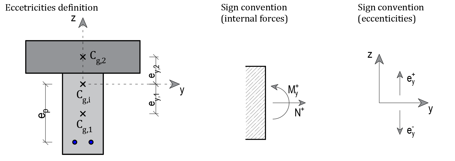
Cg,i . . . . der Schwerpunkt des idealisierten Verbundquerschnitts (Ecm(28) wird berücksichtigt)
Cg,1 . . . . der Schwerpunkt von Teil eins – Fertigteilträger (hellgrauer Teil)
Cg,2 . . . . der Schwerpunkt von Teil zwei – Verbundplatte (dunkelgrauer Teil)
ey,1 . . . . der Abstand von Cg,1 zu Cg,i
ey,2 . . . . der Abstand von Cg,2 zu Cg,i
ep . . . . der Abstand vom Schwerpunkt der Spannbewehrung zu Cg,i
Die Schnittgrößen N1, My,1, N2 und My,2 werden für die in Drittanbieter-Software modellierte Verbundstruktur ermittelt, die in vertikaler Richtung beansprucht wird. Für die korrekte Eingabe der Schnittgrößen in die RCS-Anwendung muss eine Umrechnung wie folgt durchgeführt werden:
Teil 1 (Fertigteilträger)
\[N_{1}^{T} = N_{1}\]
\[M_{y}^{T},_{1} = M_{y},_{1}-N_{1}\times e_{y},_{1}\]
N1T . . . . die Normalkraft im Fertigteilträger, umgerechnet auf den Schwerpunkt des idealisierten endgültigen Verbundquerschnitts Cg,I (negativer Wert für Druckkraft)
My,1T . . . das Biegemoment im Fertigteilträger, umgerechnet auf den Schwerpunkt des idealisierten endgültigen Verbundquerschnitts Cg,i
N1 . . . . die Normalkraft im Fertigteilträger, bezogen auf den Schwerpunkt des Fertigteilträgers Cg,1
My,1 . . . das Biegemoment im Fertigteilträger, bezogen auf den Schwerpunkt des Fertigteilträgers Cg,1
ey,1 . . . . der Abstand des Schwerpunkts des Fertigteilträgers Cg,1 vom Schwerpunkt des idealisierten endgültigen Verbundquerschnitts Cg,i (in diesem Fall wird der negative Wert der Exzentrizität berücksichtigt)
Teil 2 (Verbundplatte)
\[N_{2}^{T} = N_{2}\]
\[M_{y}^{T},_{2} = M_{y},_{2}-N_{2}\times e_{y},_{2}\]
N2T . . . . die Normalkraft in der Verbundplatte, umgerechnet auf den Schwerpunkt des idealisierten endgültigen Verbundquerschnitts Cg,i
My,2T . . . das Biegemoment in der Verbundplatte, umgerechnet auf den Schwerpunkt des idealisierten endgültigen Verbundquerschnitts Cg,i
N2 . . . . die Normalkraft in der Verbundplatte, bezogen auf den Schwerpunkt der Verbundplatte Cg,2
My,2 . . . das Biegemoment in der Verbundplatte, bezogen auf den Schwerpunkt der Verbundplatte Cg,2
ey,2 . . . . der Abstand des Schwerpunkts der Verbundplatte Cg,2 vom Schwerpunkt des idealisierten endgültigen Verbundquerschnitts Cg,i (in diesem Fall wird der positive Wert der Exzentrizität berücksichtigt)
Dank dieser Umrechnung können die gesamten Schnittgrößen im Verbundquerschnitt bestimmt werden.
\[N=N_{1}^{T}+N_{2}^{T}\]
\[M_{y}=M_{y}^{T},_{1}+M_{y}^{T},_{2}\]
Hinweis: Der Umrechnungsprozess der in horizontaler Richtung wirkenden Schnittgrößen ist derselbe wie oben beschrieben.
Spannung in der Bewehrung
Der nächste wichtige Schritt ist die Bestimmung der Ausgangsspannung in den Bewehrungsstäben und Spanngliedern. Die RCS-Anwendung kann die Spannung in den Bewehrungsstäben automatisch berechnen, daher wird empfohlen, die Einstellung „Basierend auf einer Komponentenanfangsgröße" beizubehalten.
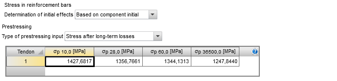
Wenn Spannbewehrung vorgesehen ist, muss die Spannung in jedem Spannglied für alle vorhandenen Bauphasen definiert werden (siehe Kapitel 2). Die RCS-Anwendung ermöglicht die Definition des Spannungswerts in Spanngliedern nach Langzeitverlusten, berechnet durch TDA („Spannung nach Langzeitverlusten"), oder die Definition geschätzter Kurz- und Langzeitverluste („Schätzung der Vorspannverluste").
Gesamtwirkungen der Vorspannung
Die RCS-Anwendung unterscheidet zwei Arten von Vorspannwirkungen – die primären und sekundären Wirkungen der Vorspannung. Beide Arten werden als auf den endgültigen Verbundquerschnitt wirkend angenommen. Vorspannwirkungen werden für jede Bauphase definiert, um Langzeit-Vorspannverluste zu erfassen. Die primären Wirkungen der Vorspannung werden automatisch gemäß den Spanngliedeligenschaften berechnet (die Position im Querschnitt, die Fläche eines Spannglieds und die Spannung in einem Spannglied in der betrachteten Bauphase). Die Schnittgrößen infolge primärer Vorspannung zum Zeitpunkt von 10 Tagen werden berechnet als:
\[N_{p}^{P},_{10}=A_{p}\times \sigma_{p},_{10}\]
\[M_{p}^{P},_{10}=A_{p}\times \sigma_{p},_{10}\times e_{p}\]
Np,10P . . . die Normalkraft im Querschnitt infolge der primären Wirkungen der verbundenen Spannbewehrung zum betrachteten Zeitpunkt (10 Tage)
Mp,10P . . . das Biegemoment im Querschnitt infolge der primären Wirkungen der verbundenen Spannbewehrung zum betrachteten Zeitpunkt (10 Tage)
Ap . . . . die Fläche der verbundenen Spannbewehrung
σp,10 . . . die Spannung in der Spannbewehrung zum betrachteten Zeitpunkt (10 Tage)
ep . . . . der Abstand vom Schwerpunkt der Spannbewehrung zum Schwerpunkt des idealisierten endgültigen Verbundquerschnitts Cg,i
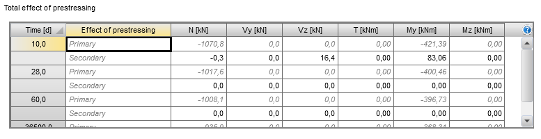
Die sekundären Wirkungen der Vorspannung werden stets vom Benutzer definiert. Die in der Tabelle definierten Schnittgrößen bestehen aus:
- Den Gesamtwirkungen der nicht verbundenen oder externen Spannbewehrung (sofern der Benutzer diesen Bewehrungstyp im globalen Berechnungsmodell definiert hat).
Die Summe der primären und sekundären Wirkungen, die in der oben gezeigten Tabelle definiert sind, wird automatisch in die Tabelle im Abschnitt „Schnittgrößen" übertragen. Es ist notwendig, die Vorspannung sorgfältig und korrekt zu definieren, um fehlerhafte Ergebnisse zu vermeiden.
Schnittgrößen
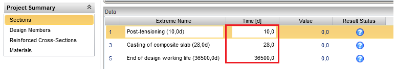
Für den korrekten Normnachweis des Verbundquerschnitts sind einige letzte Schritte erforderlich. Im „Abschnitt" ist es notwendig, „Extremwerte" für jeden Zeitpunkt zu definieren, zu dem der Normnachweis durchgeführt werden soll. Die definierten Zeitpunkte der Extremwerte müssen den in „Bauphasen" definierten Zeitpunkten entsprechen (Kap. 2). Anschließend werden die korrekten Werte der Schnittgrößen für die Berechnung des Ausgangszustands des Querschnitts aus dem Tab „Lastphasen" entnommen.
Weitere Arten von wirkenden Schnittgrößen müssen im Tab „Schnittgrößen" definiert werden. Schnittgrößen werden für jeden Extremwert separat definiert.
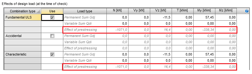
Ständige Last
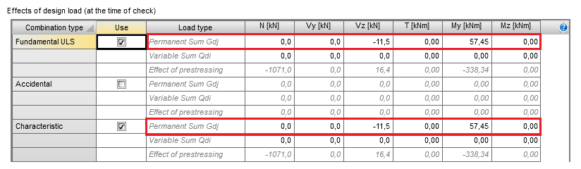
Die Zeilen mit der Bezeichnung „Ständige Summe Gdj" dienen als Eingabe für den Kombinationswert der ständigen Lasten (einschließlich Lastfaktoren), die in der betrachteten Bauphase wirken.
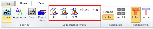
Ständige Schnittgrößen können manuell definiert oder mithilfe der Befehle im Menüband aus „Lastphasen" importiert werden. Beim Import von GZT-Schnittgrößen aus „Lastphasen" kann der Lastfaktor für die ständige Last vom Benutzer festgelegt werden.
Beim Import ständiger Schnittgrößen aus den „Lastphasen" gelten folgende Regeln:
- Der Kombinationswert der Schnittgrößen für GZT-Nachweise wird berechnet als
Ständige Summe = (Anfangswirkungen des Querschnitts – Gesamtwirkungen der Vorspannung) ·γGj,sup
- Die Kombinationswerte der Schnittgrößen für GZG-Nachweise werden berechnet als
Ständige Summe = Anfangswirkungen des Querschnitts – Gesamtwirkungen der Vorspannung
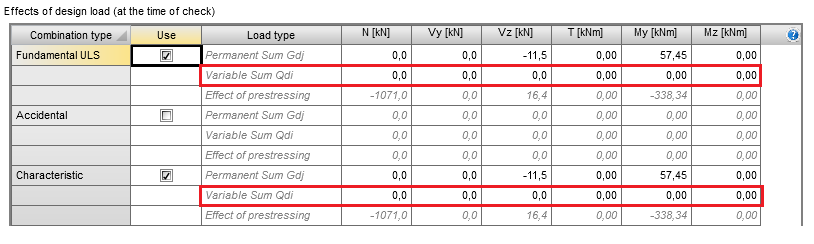
Veränderliche Last
Der resultierende Wert der Schnittgrößen infolge einer veränderlichen Last (einschließlich Kombinationslastfaktoren) wird vom Benutzer manuell definiert. Diese Werte werden in der Regel aus der globalen Tragwerksanalyse gewonnen.
Wirkungen der Vorspannung
Die Gesamtwirkungen der Vorspannung werden automatisch aus dem Tab „Lastphasen" als Summe der primären und sekundären Vorspannwirkungen importiert, die im Tab „Gesamtwirkungen der Vorspannung" definiert sind (Kap. 3.3). Diese Werte können vom Benutzer nicht bearbeitet werden.