Verificarea calculelor IDEA StatiCa pentru proiectarea îmbinărilor metalice (AISC)
Autori:

- Baris Kasapoglu, doctorand (Departamentul de Inginerie Civilă, de Mediu și Geodezică)
- Rafael Arthur Giorjao, Ph.D. (Departamentul de Știința și Ingineria Materialelor)
- Ali Nassiri, Ph.D. (Departamentul de Inginerie a Sistemelor Integrate)
- Halil Sezen, Ph.D. (Departamentul de Inginerie Civilă, de Mediu și Geodezică)
Iunie 2021
Introducere
În domeniul ingineriei structurale și civile, înțelegerea comportamentului structural și a integrității clădirii este esențială pentru a asigura siguranța ocupanților. Cu toate acestea, analiza și determinarea comportamentului unei structuri complexe supuse unei varietăți de condiții de încărcare prin metode analitice convenționale reprezintă o provocare. Prin urmare, Analiza cu Metoda Elementelor Finite (FEA) este un instrument valoros pentru modelarea numerică a structurilor fizice prea complexe pentru soluții analitice. Obiectivul principal al acestui raport este de a evalua rezultatele FEA obținute din pachetul software IDEA StatiCa pentru trei grupe de îmbinări metalice uzuale utilizate în Statele Unite (respectiv, îmbinări simple, semi-rigide și rigide) și de a le compara cu datele experimentale disponibile și cu rezultatele calculate cu un alt software FEA, ABAQUS. Răspunsul îmbinării grindă-stâlp obținut din software-ul IDEA StatiCa este apoi comparat cu calculele de proiectare efectuate conform cerințelor AISC 360, Specification for Structural Steel Building (2016), și AISC Steel Construction Manual (2017).
Acest raport include patru capitole. În Capitolele 1–3, pentru fiecare tip de îmbinare a fost ales din literatură un model de bază validat experimental. Verificările și calculele de proiectare conform codului au fost efectuate conform codurilor de construcție din S.U.A. pentru fiecare model de bază și cele zece variante ale acestuia. Rezultatele au fost apoi comparate cu predicțiile IDEA StatiCa. În plus, rezultatele FEA din IDEA StatiCa au fost comparate cu cele din ABAQUS. Toți pașii necesari și detaliile tuturor verificărilor geometrice și de proiectare conform codurilor AISC sunt incluse în anexe. Ultimul capitol conține evaluarea generală a software-ului IDEA StatiCa în ceea ce privește acuratețea și compatibilitatea cu cerințele codurilor de construcție din S.U.A. pentru îmbinările metalice.
1 ÎMBINĂRI SIMPLE
În acest studiu, capacitățile de rezistență la proiectare ale zece epruvete de îmbinare articulată au fost calculate conform cerințelor AISC 360 (2016) și AISC Construction Manual (2017). Patru epruvete de testare au fost selectate din studiul experimental realizat de McMullin și Astaneh (1988) în cadrul Departamentului de Inginerie Civilă de la Universitatea din California, Berkeley. Șase modele suplimentare au fost dezvoltate în scopuri de verificare prin modificarea parametrilor pe baza epruvetelor de testare disponibile. Ulterior, modelul de bază a fost analizat utilizând ABAQUS (2020) și IDEA StatiCa (Versiunea 20.1.3471.1), iar rezultatele au fost comparate.
Studiu Experimental
Șapte epruvete de îmbinare grindă-stâlp din oțel la scară reală au fost testate, iar rezultatele au fost prezentate în McMullin și Astaneh (1988). Fiecare epruvetă de îmbinare a fost prinsă cu șuruburi de grindă și sudată de stâlp cu secțiuni din corniere duble. Scopul principal al acestor teste este de a aplica doar forță de forfecare în îmbinare cu încovoiere sau moment foarte mic. Pentru a atinge acest obiectiv, actuatorul din apropierea îmbinării aplică forța de forfecare. Actuatorul din apropierea vârfului consolei urmărește să mențină grinда orizontală și să limiteze rotația (încovoierea) îmbinării.

Schema instrumentației utilizate în timpul experimentului (McMullin și Astaneh, 1988)
Calcule de Proiectare conform Codului și Comparații
Capacitățile de rezistență la proiectare (\(\phi\)Rn) ale îmbinărilor au fost calculate conform cerințelor AISC Specification for Structural Steel Buildings (AISC 360, 2016) și AISC Steel Construction Manual (AISC Manual, 2017). Rezistența nominală, Rn, și factorul de rezistență corespunzător, \(\phi\), pentru fiecare stare limită de proiectare a îmbinării pentru proiectarea pe baza factorilor de încărcare și rezistență (LRFD) sunt furnizate în Capitolul J al AISC 360. Următoarele 13 verificări de proiectare au fost efectuate conform ecuațiilor de proiectare LRFD incluse în AISC 360 sau AISC Manual.
- Verificare forfecare șuruburi (Ec. J3-1, AISC 360-16)
- Verificare întindere șuruburi (Ec. J3-1, AISC 360-16)
- Presiune pe grindă din șuruburi (AISC 360-16, Ec. J3-6a)
- Sfâșiere pe grindă din șuruburi (AISC 360-16, Ec. J3-6c)
- Presiune pe corniere din șuruburi (AISC 360-16, Ec. J3-6a)
- Sfâșiere pe corniere din șuruburi (AISC 360-16, Ec. J3-6c)
- Rupere la forfecare pe corniere (partea grinzii) (AISC 360-16, Ec. J4-4)
- Forfecare bloc pe corniere (partea grinzii) (AISC 360-16, Ec. J4-5)
- Curgere la forfecare pe corniere (AISC 360-16, Ec. J4-3)
- Curgere la forfecare pe grindă (AISC 360-16, Ec. J4-3)
- Rupere suduri pe corniere (partea rezemului) (Pagina 9-5, AISC Manual)
- Capacitate sudură (Pagina 10–11, AISC Manual)
- Capacitate sudură (fără excentricitate) (AISC 360-16, Ec. J4-2)
Analiza IDEA StatiCa
IDEA StatiCa verifică patru scenarii diferite de cedare pentru acest tip de îmbinare metalică: (1) cedarea plăcii, (2) cedarea șuruburilor, (3) cedarea sudurii și (4) flambaj. Cele patru epruvete de testare selectate (Tabelul 1.4) și șase modele suplimentare (Tabelul 1.6) au fost modelate în IDEA StatiCa și analizate sub o forță de forfecare, după cum se arată în Figura 1.9. În software, locația forței de forfecare poate fi selectată în mod arbitrar. Au fost investigate două locații ale forței de forfecare: (1) în șuruburi și (2) la fața stâlpului.
Compararea capacităților de forfecare: Patru epruvete testate
| Capacități de Rezistență | Test Nr. 4 | Test Nr. 5 | Test Nr. 6 | Test Nr. 9 |
| Rezistență prin IDEA StatiCa - forță aplicată pe șuruburi (kips) | 130.2 | 73.4 | 31.3 | 61.3 |
| Rezistență prin AISC Manual - forță aplicată pe șuruburi (kips) | 186.8 | 114.6 | 48.1 | 126.6 |
| Rezistență prin IDEA StatiCa - forță aplicată pe sudură (kips) | 216.6 | 145.4 | 74.8 | 168.0 |
| Rezistență prin AISC 360-16 Ec. J2.4 - forță aplicată pe sudură (kips) | 228.3 | 161.5 | 94.7 | 201.9 |
| Forfecare ultimă măsurată în timpul experimentelor (kips) | 230 | 205 | 117 | 192 |
Compararea capacităților de forfecare: șase modele suplimentare
| Capacități de Rezistență | Model 1 | Model 2 | Model 3 | Model 4 | Model 5 | Model 6 |
| Rezistență prin IDEA StatiCa - forță aplicată pe șuruburi (kips) | 127.3 | 200.1 | 129.1 | 130.2 | 132.3 | 127.9 |
| Rezistență prin AISC Manual - forță aplicată pe șuruburi (kips) | 233.5 | 186.8 | 139.9 | 186.8 | 186.8 | 214.4 |
| Rezistență prin IDEA StatiCa - forță aplicată pe sudură (kips) | 229.0 | 226.7 | 136.0 | 216.5 | 213.3 | 234.1 |
| Rezistență prin AISC 360-16 Ec. J2.4 - forță aplicată pe sudură (kips) | 285.4 | 228.1 | 139.9 | 228.1 | 228.1 | 285.4 |
Rezumat și Compararea Rezultatelor
Două capacități diferite de sudură au fost calculate pentru fiecare epruvetă de testare conform cerințelor de proiectare AISC LRFD. Pentru aceleași patru epruvete de testare, două capacități diferite de sudură au fost calculate din modelele IDEA StatiCa prin aplicarea forței de forfecare în locații diferite. În toate scenariile de încărcare, s-a constatat că cea mai slabă componentă a îmbinărilor era sudura. Rezistențele de control sau cele mai mici rezistențe calculate corespunzătoare capacităților de sudură sunt prezentate și comparate cu capacitatea ultimă de forfecare a sudurii măsurată în timpul experimentului.
Capacitățile de sudură ale epruvetelor de testare au fost calculate în două moduri diferite urmând cerințele codului AISC LRFD (AISC 360-16 și AISC Manual, 2017). Pentru Testul Nr. 4, dacă se urmează Ecuația J2.4 din AISC 360-16, capacitatea de proiectare a sudurii epruvetei este calculată ca 228,3 kips. În această soluție, nu se ia în considerare nicio excentricitate. Pentru a compara această abordare cu analiza IDEA StatiCa, forța de forfecare verticală a fost aplicată pe sudură (paralelă cu linia de sudură) și capacitatea de sudură a acestei epruvete a fost calculată ca 216,6 kips, foarte apropiată de cea calculată din Ecuația J2.4 din AISC 360-16 (228,3 kips).
Când forța de forfecare este aplicată pe șuruburi (forță verticală externă paralelă cu linia de șuruburi) în modelul IDEA StatiCa, capacitatea îmbinării a fost calculată ca 130,2 kips. Dacă capacitatea de sudură este calculată urmând ecuația de rezistență LRFD pentru suduri (Pagina 10-11 din AISC Construction Manual, 2017), care ia în considerare excentricitatea încărcării pe partea rezemului, capacitatea de sudură a epruvetei este calculată ca 186,8 kips. Cu toate acestea, în mod conservativ, această ecuație AISC LRFD nu ține cont de excentricitatea rezultată din distanța dintre șuruburi și sudură. Se consideră că această ipoteză este motivul diferenței dintre rezultatele calculate din IDEA StatiCa și ecuația de rezistență LRFD din AISC Manual (2017).
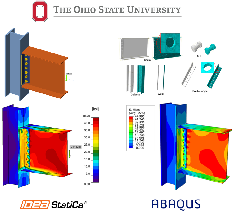
Compararea Rezultatelor IDEA StatiCa și ABAQUS
În general, a existat o bună concordanță între rezultatele celor două pachete software. În cazul 1, în care încărcarea a fost aplicată pe centrul de greutate al grupului de șuruburi, s-a observat o deformație mai mare pe cornierele duble în modelul ABAQUS. De asemenea, tensiunea maximă prognozată pe grindă, stâlp și liniile de sudură a fost ușor mai mare în modelul ABAQUS. În plus, o distribuție ușor diferită a tensiunilor a fost observată pe grindă în modelul ABAQUS. Deși aplicarea încărcării pe grupul de șuruburi nu este obișnuită în software-ul tradițional de elemente finite, o astfel de discrepanță ar putea fi asociată cu formulări diferite ale contactului sau tipuri de elemente (respectiv, element solid în ABAQUS față de element de tip placă în IDEA StatiCa). De asemenea, datorită naturii constrângerii de tip tie, tensiuni mai mari au fost obținute pe stâlp în modelul ABAQUS. În cazul 2, în care încărcarea a fost aplicată pe liniile de sudură, s-a observat o concordanță mult mai bună între cele două modele. În ambele modele, s-a constatat că cea mai slabă componentă a îmbinărilor era liniile de sudură. Acest lucru este, de asemenea, consistent cu verificările de proiectare conform codului LRFD.

Tensiunea von Mises prognozată între modelele IDEA StatiCa și ABAQUS; cazul 1 (rândul de sus): încărcarea de forfecare a fost aplicată pe centrul de greutate al grupului de șuruburi, și cazul 2 (rândul de jos): încărcarea de forfecare a fost aplicată pe liniile de sudură
2 ÎMBINĂRI SEMI-RIGIDE
În acest capitol, capacitățile de rezistență la proiectare ale zece epruvete de îmbinare semi-rigidă au fost calculate conform cerințelor AISC 360 (2016) și AISC Construction Manual (2017). Aceste epruvete au fost selectate din studiul experimental realizat de Azizinamini et al. (1985) în cadrul Departamentului de Inginerie Civilă de la Universitatea din Carolina de Sud. Toate epruvetele au fost analizate utilizând IDEA StatiCa, în timp ce una dintre ele a fost analizată utilizând ABAQUS (2020). Ulterior, rezultatele au fost comparate.
Studiu Experimental privind Îmbinările Semi-Rigide
Mai multe îmbinări semi-rigide alcătuite din corniere duble și tălpi superioare și inferioare ale grinzilor au fost supuse încărcărilor statice și ciclice pentru a investiga comportamentul lor moment-rotație. O pereche de epruvete a fost testată în același timp, după cum se arată în Figura 2.1. O parte a secțiunilor de grindă a fost prinsă cu șuruburi de stâlp, iar cealaltă parte a fost rezemată pe suporturi de tip rolă. Mișcarea verticală a tronsonului scurt de stâlp a fost permisă de ghidaje cu role atașate la partea superioară și inferioară a stâlpului. Actuatorul hidraulic a fost utilizat pentru a aplica încărcarea pe stâlp, iar îmbinarea a transferat încărcarea către grinzi.

Configurația de testare utilizată de Azizinamini et al. (1985)
Calcule de Proiectare conform Codului și Comparații
Capacitățile de rezistență la proiectare (\(\phi\)Rn) ale îmbinărilor au fost calculate conform cerințelor AISC 360 (2016) și AISC Manual (2017). Rezistența nominală, Rn, și factorul de rezistență corespunzător, \(\phi\) pentru fiecare stare limită LRFD de proiectare a îmbinării sunt furnizate în Capitolul J al AISC 360. Se presupune că cornierele superioare și inferioare asigură rezistența la moment, iar cornierele duble de inimă sunt utilizate pentru rezistența la forfecare a îmbinării, în mod conservativ.
Capacitatea de rezistență la proiectare a cornierelor duble de inimă
Următoarele 14 verificări de proiectare au fost efectuate conform ecuațiilor de proiectare LRFD incluse în AISC 360 sau AISC Manual pentru capacitatea de rezistență la proiectare a cornierelor duble de inimă.
- Cornier (partea grinzii)
- Forfecare șuruburi Ec. J3-1, AISC 360-16
- Presiune și sfâșiere șuruburi Ec. J3-6, AISC 360-16
- Curgere la forfecare Ec. J4-3, AISC 360-16
- Rupere la forfecare Ec. J4-4, AISC 360-16
- Forfecare bloc Ec. J4-5, AISC 360-16
- Cornier (partea stâlpului)
- Forfecare șuruburi Ec. J3-1, AISC 360-16
- Presiune și sfâșiere șuruburi Ec. J3-6, AISC 360-16
- Curgere la forfecare Ec. J4-3, AISC 360-16
- Rupere la forfecare Ec. J4-4, AISC 360-16
- Forfecare bloc Ec. J4-5, AISC 360-16
- Capacitate de întindere rezultantă datorată efectului de pârghie Partea 9, AISC Manual
- Grindă
- Presiune și sfâșiere șuruburi Ec. J3-6, AISC 360-16
- Curgere la forfecare Ec. J4-3, AISC 360-16
- Stâlp
- Presiune și sfâșiere șuruburi Ec. J3-6, AISC 360-16
Capacitatea de proiectare a două corniere duble de inimă (în epruvetele 14S1 și 14S2) a fost controlată de forfecarea bloc a șuruburilor pe cornierele atașate de grindă, în timp ce presiunea și sfâșierea șuruburilor pe grindă au controlat capacitățile de proiectare la forfecare ale celorlalte opt epruvete.
Capacitatea de rezistență la proiectare a cornierelor superioare și inferioare de reazem
Următoarele 16 verificări de proiectare au fost efectuate conform ecuațiilor LRFD incluse în AISC 360 sau AISC Manual pentru capacitatea de rezistență la proiectare a cornierelor superioare și inferioare de reazem.
- Cornier superior și inferior de reazem (partea grinzii)
- Curgere la întindere Ec. J4-1, AISC 360-16
- Rupere la întindere Ec. J4-2, AISC 360-16
- Compresiune Sec. J4.4, AISC 360-16
- Forfecare șuruburi Ec. J3-1, AISC 360-16
- Presiune și sfâșiere șuruburi Ec. J3-6, AISC 360-16
- Forfecare bloc Ec. J4-5, AISC 360-16
- Cornier superior și inferior de reazem (partea stâlpului)
- Curgere la forfecare Ec. J4-3, AISC 360-16
- Rupere la forfecare Ec. J4-4, AISC 360-16
- Capacitate de întindere datorată efectului de pârghie Pagina 9-10, AISC Manual
- Grindă
- Presiune și sfâșiere șuruburi Ec. J3-6, AISC 360-16
- Rezistență la încovoiere Sec. F13.1, AISC 360-16
- Forfecare bloc Ec. J4-5, AISC 360-16
- Stâlp
- Forfecare inimă panou Ec. J10-9, AISC 360-16
- Încovoiere locală a tălpii Ec. J10-1, AISC 360-16
- Curgere locală a inimii Ec. J10-2, AISC 360-16
- Strivire locală a inimii Ec. J10-4, AISC 360-16
Capacitățile de proiectare ale tuturor cornierelor superioare și inferioare de reazem au fost controlate de capacitatea de întindere datorată efectului de pârghie pe șuruburile cornierului atașat de stâlp. Capacitatea de proiectare a tuturor cornierelor superioare și inferioare de reazem a fost controlată de capacitatea de întindere datorată efectului de pârghie.
Analiza IDEA StatiCa
Cele zece epruvete de testare au fost modelate în IDEA StatiCa și analizate sub o forță de forfecare aplicată la o anumită distanță față de stâlp. Distanța a fost selectată să fie egală cu cea dintre axa stâlpului și rezemul grinzii. Rezemul grinzii este presupus a fi la 120 in. față de axa stâlpului pentru primele patru epruvete, în timp ce pentru celelalte șase epruvete distanța a fost de 72 in. Toate epruvetele cedează deoarece cornierele superioare atașate de stâlp depășesc limita de deformație plastică, definită ca 5% de software.
Diagramele moment-rotație împreună cu rezistențele determinate prin calculul tradițional AISC (albastru) și IDEA StatiCa (portocaliu) sunt prezentate în imaginile următoare.

Relația moment-rotație pentru Testul Nr: 14S1 (stânga) și 14S2 (dreapta)

Relația moment-rotație pentru Testul Nr: 14S3 (stânga) și 14S4 (dreapta)

Relația moment-rotație pentru Testul Nr: 8S1 (stânga) și 8S2 (dreapta)

Relația moment-rotație pentru Testul Nr: 8S3 (stânga) și 8S4 (dreapta)

Relația moment-rotație pentru Testul Nr: 8S5 (stânga) și 8S6 (dreapta)
Analiza ABAQUS
În această secțiune, rezultatele obținute din IDEA StatiCa au fost comparate cu cele din pachetul software ABAQUS (2020). În acest studiu, epruveta Testul Nr. 14S1 a fost aleasă ca model de bază. Simulările numerice cu condiții aproape identice (respectiv, în ceea ce privește proprietățile materialelor, condițiile la limită și încărcarea) au fost efectuate utilizând atât IDEA StatiCa, cât și ABAQUS. Modelul a fost inițial proiectat în IDEA StatiCa, iar apoi ansamblul (inclusiv grinда, stâlpul, cornierele de inimă și cornierele superioare și inferioare de reazem) a fost importat în ABAQUS utilizând platforma de vizualizare a IDEA StatiCa. Ulterior, un model simplificat pentru șurub a fost proiectat și adăugat la modelul ABAQUS.

Configurarea modelului de îmbinare semi-rigidă în ABAQUS
În ABAQUS, tipul de element a fost C3D8R (tensiune 3D, element solid liniar cu 8 noduri, integrare redusă), iar un total de 562.377 de elemente au fost generate în model.

Densitățile plasei modelului ABAQUS
Simulările numerice au fost efectuate pe patru procesoare (Intel Xenon (R) CPU E5-2698 v4 @ 2.20GHz), iar fiecare simulare a durat aproximativ 535 de minute.
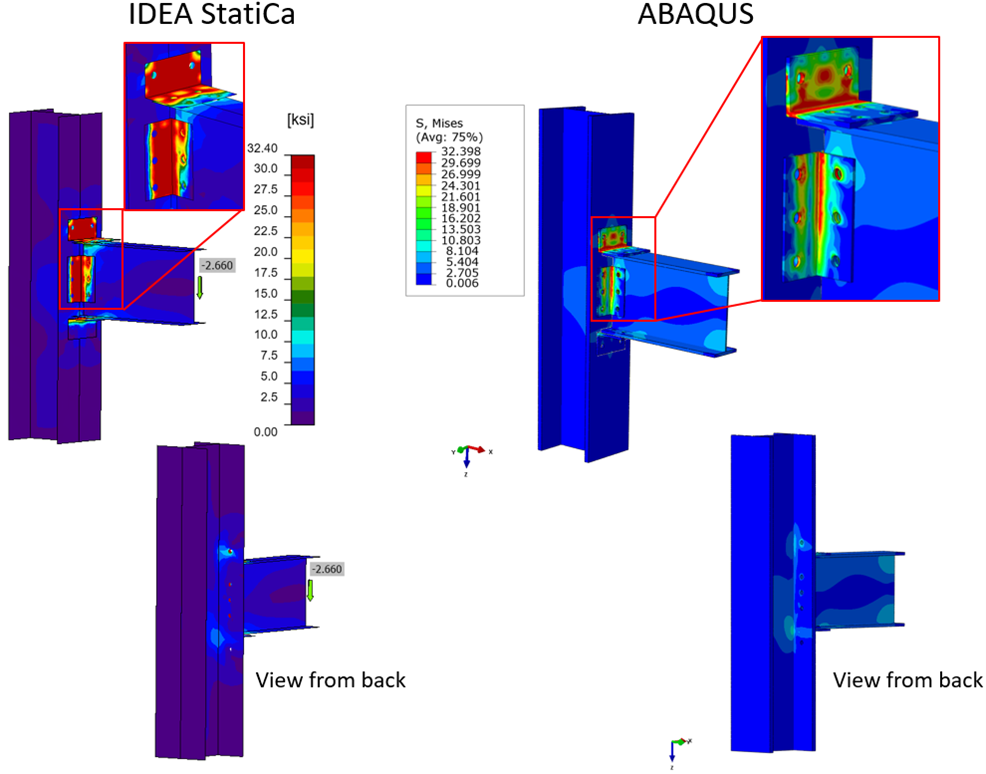
Compararea tensiunii von-Mises prognozate între IDEA StatiCa și ABAQUS

Compararea vederii laterale între IDEA StatiCa și ABAQUS cu un factor de scară al deformației de zece
În general, a existat o bună concordanță între rezultatele celor două pachete software. Cu toate acestea, mai multă deformație a fost capturată pe cornierele de inimă, tălpile superioare și inferioare în modelul IDEA StatiCa. De asemenea, distribuțiile de tensiuni pe cornierele de inimă au fost ușor diferite între cele două modele. Acest lucru se datorează cel mai probabil faptului că în modelul ABAQUS au fost utilizate elemente solide cu integrare redusă. În ambele modele, s-a constatat că cea mai slabă componentă a ansamblului era talpa superioară în întindere sub forța de forfecare aplicată în jos, care introduce întindere în talpa superioară.
3 ÎMBINĂRI RIGIDE
În acest capitol, capacitățile de rezistență la proiectare ale zece epruvete de îmbinare rigidă au fost calculate conform cerințelor AISC 360 (2016) și AISC Construction Manual (2017). Epruveta de bază a fost selectată din studiul experimental realizat de Sato et al. (2007) în cadrul Departamentului de Inginerie Structurală de la Universitatea din California, San Diego. Epruveta de bază și nouă modele de variație suplimentare au fost analizate utilizând IDEA StatiCa, în timp ce epruveta de bază a fost analizată și cu ABAQUS (2020).
Studiu Experimental privind Îmbinările Rigide
Trei îmbinări moment cu plăci de flanșă cu șuruburi (BFP) la scară reală au fost supuse testării ciclice la Universitatea din California, San Diego. Toate epruvetele au îndeplinit cerințele AISC Seismic Provisions for Structural Steel Buildings pentru îmbinările grindă-stâlp ale cadrelor cu moment special. Distanța de contravântuire laterală pentru epruvete a fost determinată în conformitate cu această prevedere. Deplasările verticale au fost aplicate de un actuator hidraulic la vârful grinzii.

Calcule de Proiectare conform Codului și Comparații
Capacitățile de rezistență la proiectare (\(\phi\)Rn) ale zece îmbinări rigide au fost calculate conform cerințelor AISC Specification for Structural Steel Buildings (AISC 360, 2016) și AISC Steel Construction Manual (AISC Manual, 2017). Rezistența nominală, Rn, și factorul de rezistență corespunzător, \(\phi\), pentru fiecare stare limită de proiectare a îmbinării pentru proiectarea pe baza factorilor de încărcare și rezistență (LRFD) sunt furnizate în Capitolul J al AISC 360.
Capacitatea de rezistență la proiectare a plăcilor de inimă simple
Următoarele opt verificări de proiectare au fost efectuate conform ecuațiilor de proiectare LRFD incluse în AISC 360 sau AISC Manual pentru capacitățile de rezistență la proiectare ale plăcii de inimă simple.
- Placă de inimă
- Forfecare șuruburi Ec. J3-1, AISC 360-16
- Presiune și sfâșiere șuruburi Ec. J3-6, AISC 360-16
- Curgere la forfecare Ec. J4-3, AISC 360-16
- Rupere la forfecare Ec. J4-4, AISC 360-16
- Forfecare bloc Ec. J4-5, AISC 360-16
- Forfecare sudură Ec. 8-2, AISC Manual
- Grindă
- Forfecare șuruburi Ec. J3-1, AISC 360-16
- Presiune și sfâșiere șuruburi Ec. J3-6, AISC 360-16
Din capacitățile de proiectare calculate pentru cele zece epruvete de testare, capacitatea de proiectare a modelului 2 a fost controlată de ruperea la forfecare, în timp ce forfecarea șuruburilor a condus la cedare pentru celelalte opt epruvete.
Capacitatea de rezistență la proiectare a plăcilor de flanșă
Următoarele 13 verificări de proiectare au fost efectuate conform ecuațiilor de proiectare LRFD incluse în AISC 360 sau AISC Manual pentru capacitățile de rezistență la proiectare ale plăcilor de flanșă.
- Placă de flanșă
- Forfecare șuruburi Ec. J3-1, AISC 360-16
- Presiune și sfâșiere șuruburi Ec. J3-6, AISC 360-16
- Curgere la întindere Ec. J4-3, AISC 360-16
- Rupere la întindere Ec. J4-4, AISC 360-16
- Forfecare bloc Ec. J4-5, AISC 360-16
- Compresiune Sec. J4-4, AISC 360-16
- Grindă
- Presiune și sfâșiere șuruburi Ec. J3-6, AISC 360-16
- Încovoiere Sec. F13.1, AISC 360-16
- Forfecare bloc Ec. J4-5, AISC 360-16
- Stâlp
- Forfecare inimă panou Ec. J10-9, AISC 360-16
- Încovoiere locală a tălpii Ec. J10-1, AISC 360-16
- Curgere locală a inimii Ec. J10-2, AISC 360-16
- Strivire locală a inimii Ec. J10-4, AISC 360-16
Din capacitățile de proiectare calculate pentru cele zece epruvete de testare, capacitatea de proiectare a șapte epruvete a fost controlată de forfecarea panoului de inimă, două epruvete au fost controlate de forfecarea șuruburilor și o epruvetă a fost controlată de forfecarea bloc. Capacitățile la moment ale epruvetelor au fost calculate prin înmulțirea capacității de proiectare de control cu brațul momentului, conform Tabelului 3.5. Brațul momentului este egal cu înălțimea grinzii pentru forfecarea șuruburilor, în timp ce este egal cu suma înălțimii grinzii și a grosimii plăcii pentru rezistențele la forfecarea panoului de inimă și forfecarea bloc (BFP, modelele 1, 2, 3, 4, 5, 6 și 8).
Analiza IDEA StatiCa
Cele zece epruvete de îmbinare metalică rigidă au fost modelate în IDEA StatiCa și analizate sub o forță de forfecare aplicată la 177,5 in. față de axa stâlpului, conform raportului de testare. Forța de forfecare a fost mărită incremental până când îmbinările și-au atins capacitățile în IDEA StatiCa.

Analiza ABAQUS
În această secțiune, rezultatele obținute din IDEA StatiCa au fost comparate cu pachetul software ABAQUS (versiunea 2020). Testul BFP a fost ales ca model de bază. Simulările numerice cu condiții aproape identice (respectiv, în ceea ce privește proprietățile materialelor, condițiile la limită și încărcarea) au fost efectuate utilizând atât IDEA StatiCa, cât și ABAQUS. Modelul a fost inițial proiectat în IDEA StatiCa, iar apoi ansamblul (inclusiv grinда, stâlpul și plăcile) a fost importat în ABAQUS utilizând platforma de vizualizare a IDEA StatiCa. Ulterior, un model simplificat pentru șurub a fost proiectat și adăugat la modelul ABAQUS.
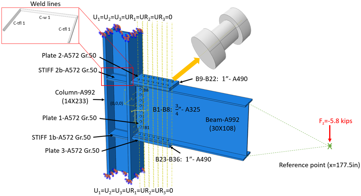
Configurarea modelului în ABAQUS
În ABAQUS, tipul de element a fost C3D8R (tensiune 3D, element solid liniar cu 8 noduri, integrare redusă), iar un total de 681.016 elemente au fost generate în model. Simulările numerice au fost efectuate pe opt procesoare (Intel Xenon (R) CPU E5-2698 v4 @ 2.20GHz), iar simularea a durat aproximativ 685 de minute.

A existat o bună concordanță între rezultatele celor două pachete software. Distribuțiile de tensiuni pe grindă și stâlp au fost foarte apropiate. Cu toate acestea, tensiuni ușor mai mari au fost prognozate pe stâlp, placa 1 și elementele de rigidizare în modelul ABAQUS, cel mai probabil datorită naturii constrângerii de tip tie. Încărcarea prognozată pe șuruburi și grupurile de suduri a fost, de asemenea, foarte apropiată între cele două software-uri.
4 REZUMAT ȘI CONCLUZII
IDEA StatiCa este un pachet software de analiză cu Metoda Elementelor Finite (FEA) bazat pe componente pentru proiectarea îmbinărilor metalice. Poate fi utilizat pentru evaluarea structurală sau proiectarea unei varietăți de îmbinări metalice sudate și cu șuruburi și plăci de bază. Obiectivul principal al acestui raport a fost de a verifica rezultatele FEA obținute din pachetul software IDEA StatiCa pentru trei tipuri de îmbinări metalice utilizate frecvent în Statele Unite (respectiv, simple, semi-rigide și rigide) conform codurilor de construcție din S.U.A. Răspunsul experimental măsurat a fost disponibil pentru epruvetele de îmbinare selectate în scopuri de verificare în acest studiu. Pentru fiecare tip de îmbinare și zece variante ale acestuia, mai întâi, verificările și calculele conform codului au fost efectuate urmând cerințele AISC 360, Specification for Structural Steel Building (2016), și AISC Steel Construction Manual (2017). Ulterior, rezultatele au fost comparate cu predicțiile IDEA StatiCa. În plus, rezultatele din IDEA StatiCa au fost comparate cu ABAQUS, care este un alt cod FEA robust pe piață. Răspunsurile măsurate ale epruvetelor de testare au fost, de asemenea, utilizate pentru a compara și a înțelege mai bine comportamentul general și modul de cedare al modelelor de îmbinare.
În general, a existat o bună concordanță între rezultatele IDEA StatiCa, verificările conform codurilor S.U.A. și rezultatele ABAQUS. Rezultatele calculate diferă de cele obținute cu IDEA StatiCa, posibil deoarece AISC este un cod de proiectare și poate fi conservativ, în timp ce software-ul este destinat să surprindă comportamentul real, care se preconizează a fi mai precis.
Deși există multe pachete software FEA pe piață capabile să prognozeze răspunsul structural general la o varietate de condiții de încărcare, există o lipsă de instrumente FEA specializate cu accent pe proiectarea îmbinărilor. Comparativ cu alte pachete software FEA de pe piață, software-ul IDEA StatiCa are multe avantaje. Pe lângă ușurința de utilizare, cea mai importantă caracteristică a IDEA StatiCa s-a dovedit a fi timpul de calcul, în care rezultatele pot fi obținute într-o fracțiune din timpul necesar față de codurile FEA convenționale, cum ar fi ABAQUS. Acest lucru îi va ajuta pe ingineri să evalueze și să modifice mai rapid și mai eficient proiectul preliminar al îmbinării, dacă sunt necesare modificări. În plus, în pachetele software FEA obișnuite, încărcările și capacitățile elementelor de îmbinare (respectiv, șuruburi, suduri, plăci) trebuie extrase din model în etapa de post-procesare, ceea ce reprezintă o sarcină greoaie și consumatoare de timp. Cu toate acestea, în IDEA StatiCa, rezultatele sunt calculate și raportate direct. De asemenea, în IDEA StatiCa, încărcarea poate fi aplicată direct în orice locații/elemente ale îmbinării, în timp ce în codurile FEA tipice acest lucru trebuie realizat prin definirea punctului de referință și cuplarea acestuia cu îmbinarea, ceea ce reprezintă un pas suplimentar.
O discrepanță minoră a fost totuși constatată în ceea ce privește contactele definite între plăci și fețele stâlpului/grinzii, deși același tip de analiză a fost efectuat, respectiv deformație mică. Aceasta ar putea fi datorată diferențelor dintre elementele solide și elementele de tip placă sau algoritmului (algoritmilor) de contact utilizați în cele două software-uri. De asemenea, modul în care codul IDEA StatiCa calculează și utilizează dimensiunea optimă a elementului nu a fost clar. În plus, datorită limitei de deformație plastică recomandate de 5% de Eurocode (EN1993-1-5 app. C par. C8 nota 1), care este definită ca valoare implicită în software-ul IDEA StatiCa, au fost observate moduri diferite de cedare.
Datorită capacităților rapide și ușoare de modelare și analiză a îmbinărilor din IDEA StatiCa, modelarea neliniară complicată și analiza dinamică consumatoare de timp a structurilor metalice mari pot fi efectuate relativ rapid. Proprietățile îmbinărilor în structurile cadru grindă-stâlp pot fi definite pe baza analizelor și verificărilor de proiectare finalizate în IDEA StatiCa. Ulterior, modelul de îmbinare poate fi revizuit și re-analizat dacă este necesar după finalizarea analizei cadrului utilizând un software de analiză structurală, de exemplu SAP2000. Îmbinările pot fi făcute mai slabe sau mai puternice în IDEA StatiCa în funcție de performanța optimă dorită a modelului de cadru structural. O abordare ușoară și mai robustă pentru dezvoltarea răspunsului moment-rotație al îmbinărilor în IDEA StatiCa va fi foarte utilă, deoarece în programe precum SAP2000 răspunsul moment-rotație al îmbinărilor trebuie definit ca parte a modelării structurilor cadru.
Software-ul IDEA StatiCa este la fel de bun ca Interfața sa Grafică cu Utilizatorul. Dacă interfața grafică nu este bine executată, utilizatorii vor întâmpina dificultăți în utilizarea aplicației sau a software-ului. IDEA StatiCa a proiectat-o bine. Alături de o interfață grafică bună — se observă și calitatea software-ului. Urmarea unui set de convenții sau standarde asigură consecvența și facilitează navigarea utilizatorilor în software. Un limbaj standard și consecvent asigură că utilizatorii vor înțelege termenii atunci când îi întâlnesc. Modelele sunt ușor de modificat, permițând explorarea rapidă a variabilelor și verificarea.
Software-ul se actualizează constant, incluzând timpi de încărcare mai rapizi și chiar remedieri de erori pentru a îmbunătăți experiența generală a utilizatorului.
Referințe
[1] AISC (2016). "Specification for Structural Steel Buildings," American Institute of Steel Construction ANSI/AISC 360-16, Chicago, Illinois.
[2] AISC (2017). "Steel Construction Manual," ediția a 15-a, American Institute of Steel Construction, Chicago, Illinois.
[3] McMullin, K. M., & Astaneh-Asl, A. (1988). Analytical and experimental studies of double-angle framing connections. Structural Engineering, Mechanics, and Materials, Department of Civil Engineering, University of California, Berkeley.
[4] ABAQUS 2020, Dassault Systemes Simulia Corporation, Providence, RI, USA.
[5] IDEA StatiCa s.r.o., Sumavska 519/35, Brno, 602 00 Czech Republic; https://www.ideastatica.com/support-center/general-theoretical-background
[6] Azizinamini, A., Bradburn, J. H., and Radziminski, J. B. (1985). Static and cyclic behavior of semi-rigid steel beam-column connections. University of South Carolina.
[7] Sato, A., Newell, J., and Uang, C. M. (2007). Cyclic testing of bolted flange plate steel moment connections for special moment frames. Final Repor to American Institute of Steel Construction.
Versiunea completă a raportului poate fi descărcată prin linkul de mai jos:
Descărcări atașate
- Final Report_OSU.pdf (PDF, 7,2 MB)