
Limitări cunoscute pentru Detail 3D
Introducere
La începutul acestui text, să definim pentru ce este destinată aplicația. În versiunea actuală, am dezvoltat instrumente și am verificat soluția doar pentru ancorarea structurilor metalice în blocuri simple de beton armat.
Textul următor este împărțit în două părți: limitările aplicației și ale metodei în sine, și limitările importului din IDEA StatiCa Connection.
Limitările aplicației
Beton armat
CSFM 3D nu este conceput pentru beton simplu sau beton slab armat. În acest caz, rezultatul calculului poate conduce la rezultate înșelătoare sau la divergența calculului neliniar.
Puteți citi mai multe în Fundamente teoretice.
Motivul principal pentru care în aplicație trebuie modelate doar elemente din beton armat este că rezistența la întindere a betonului este neglijabilă. Prin urmare, toate tensiunile de întindere trebuie preluate de armătură.
Al doilea motiv este: În IDEA StatiCa Detail 3D, mecanica fracturii nu este utilizată. Modelul nu simulează propagarea explicită a fisurilor și nici nu folosește parametrii de mecanică a fracturii pentru beton (G_f, K_IC, forma suprafeței de fractură). Betonul este modelat ca un material ductil cu o ramură plastică orizontală la compresiune – odată ce tensiunea limită de compresiune este atinsă, tensiunea rămâne constantă, iar deformațiile continuă să crească până la o limită prescrisă. Ca urmare, Detail 3D poate surprinde redistribuirea plastică a tensiunilor și deformațiilor în zonele D, dar nu modelează explicit mecanismele de cedare fragilă guvernate de mecanica fracturii (de ex., cedarea la forfecare pură a betonului simplu, propagarea instabilă a unei singure fisuri dominante etc.).
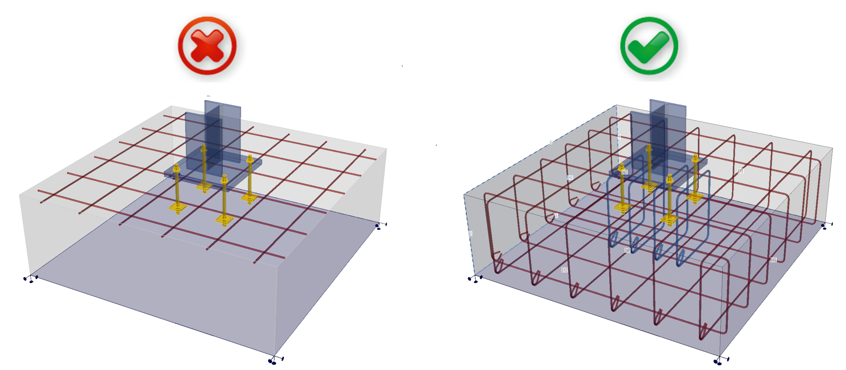
În concluzie, modelele dumneavoastră trebuie să respecte definiția betonului armat prezentată în standardele internaționale. Respectați regulile de detaliere și obțineți rezultate corecte.
Starea Limită Ultimă
Toate calculele și verificările conform codului sunt implementate doar pentru SLU. Definirea materialelor și modul de calcul în sine trebuie să fie diferite pentru SLS. Puteți vedea această diferență în Detail 2D.
Rezistența redusă a betonului comprimat
Mai întâi, să definim ce este rezistența redusă a betonului comprimat: Betonul comprimat își pierde rezistența și rigiditatea atunci când este simultan puternic fisurat la întindere, adică atunci când există deformații transversale mari de întindere.
În cazurile în care rezistența este guvernată de o bielă comprimată (diagonală comprimată) care traversează beton puternic fisurat, Detail 3D tinde să supraestimeze capacitatea (adică să fie ușor neconservativ) dacă rezultatul este interpretat direct ca și capacitate ultimă reală.
Din aceste motive, modulul 3D este adecvat pentru utilizare doar la verificarea rezistenței ancorării în blocuri simple de beton armat.
Deși este posibil să se modeleze, de exemplu, un radier pe piloți folosind reazeme pe o suprafață mică, verificarea nu este fiabilă deoarece efectul de rezistență redusă devine semnificativ, în special în problemele legate de perforare. Aceeași situație poate apărea în cazul unei plăci subțiri cu un stâlp plasat pe ea și în alte cazuri similare.
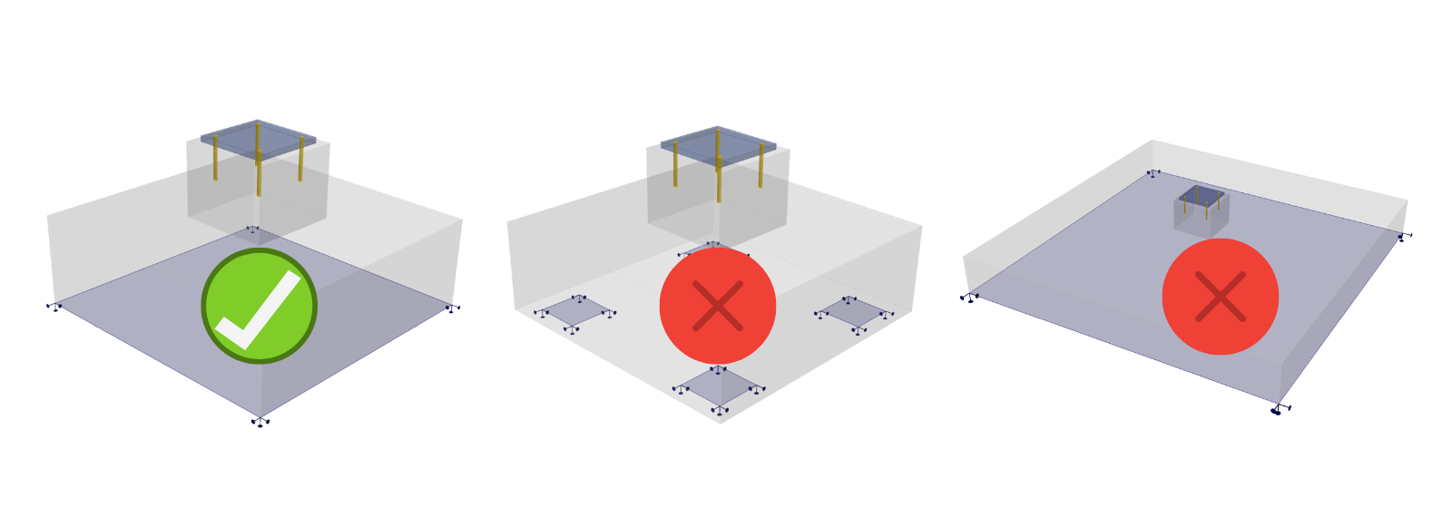
Pentru aceste situații, este necesară implementarea rezistenței reduse a betonului comprimat, care este disponibilă în prezent doar în modulul 2D. Prin urmare, modulul 3D poate fi utilizat doar pentru verificarea cedărilor în care acest efect nu are influență.
Verificarea ancorelor
Elementul ancorei este definit ca fiind capabil să transfere forțe normale de întindere sau compresiune, precum și forțe de forfecare, luând în considerare și rigiditatea la încovoiere, după cum este descris în Fundamente teoretice.
Susținem verificările conform codului în conformitate cu standardele relevante (doar EN), prin urmare IDEA StatiCa Detail poate fi utilizat independent pentru evaluarea ancorelor (ancore, armătură, beton).
Coduri implementate: EN 1992-4, EN 1993-1-8, EN 1994-1-1
Pentru verificarea altor componente ale îmbinării (suduri, plăci etc.), trebuie să utilizați IDEA StatiCa Connection, unde puteți efectua și verificarea completă a ancorelor pentru beton simplu. Ancorarea în Connection — împreună cu forțele aplicate — poate fi exportată în Detail pentru proiectarea suplimentară a armăturii.
Pentru codul ACI și codul australian, verificările conform codului ale ancorelor la forfecare și la forfecare și întindere nu sunt implementate încă, prin urmare este întotdeauna necesar să se utilizeze ambele aplicații pentru verificări complete conform codului ale ancorelor.
Răsturnare
Dacă introducerea încărcărilor provoacă răsturnarea modelului, modelul va calcula până la divergență sau atingerea unui criteriu. Aceasta durează de obicei mult timp și veți primi următorul rezultat:
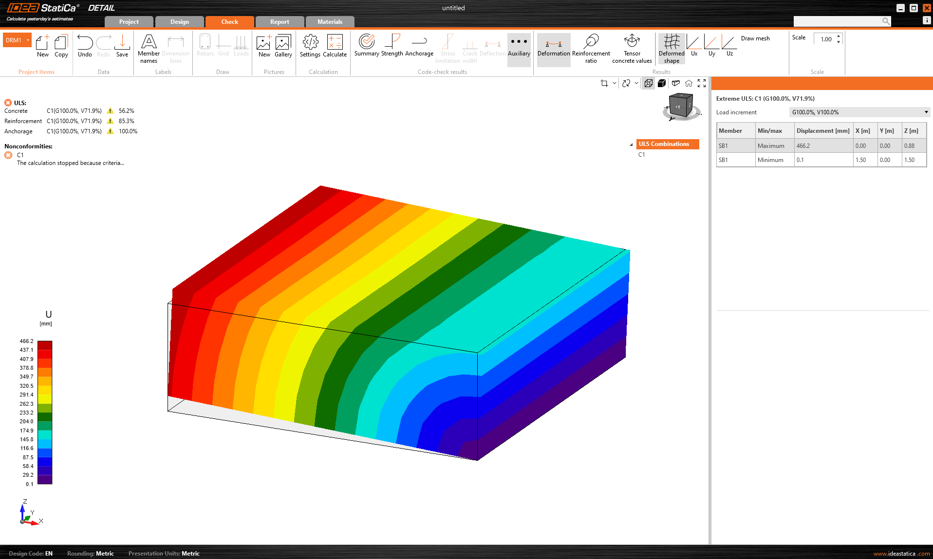
Este afișat procentul din încărcarea transferată. Mai mult, în Rezultate auxiliare este prezentată deformația extremă.
Soluție de lucru: Se recomandă calcularea oricărui model mai întâi cu Multiplicatorul dimensiunii implicite a plasei setat la o valoare ridicată (4-5). Acest multiplicator poate fi găsit în Setări -> Setări plasă. Calculul va fi rapid și veți putea vedea dacă răsturnarea este sau nu problema.
Este necesar să verificați dacă greutatea proprie a blocului de beton este inclusă, deoarece aceasta poate preveni răsturnarea modelului. Rețineți că la importul din aplicația Connection, greutatea proprie nu este introdusă automat în model — consultați textul de mai jos pentru detalii.
Limitările importului din Connection
Contacte
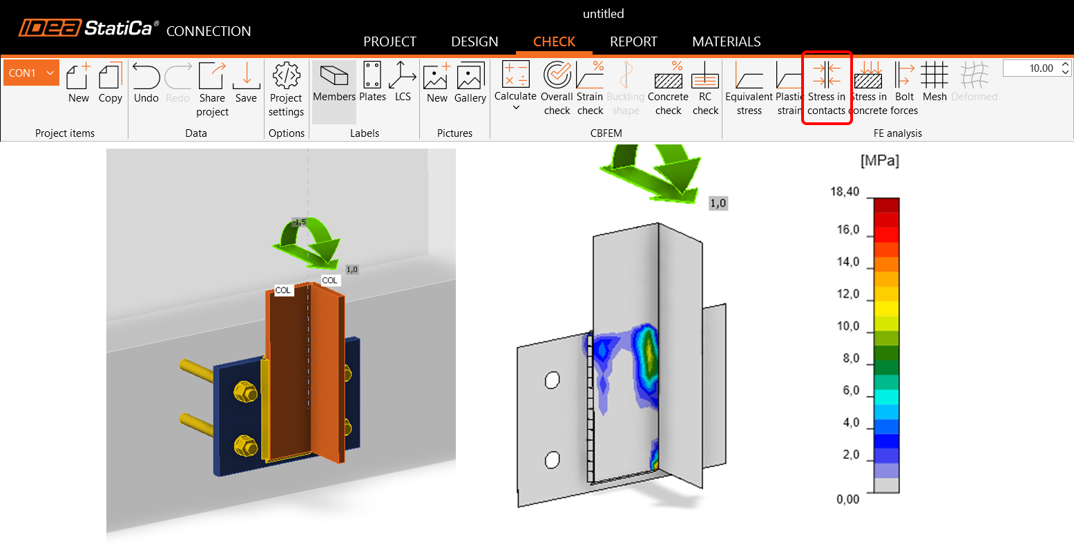
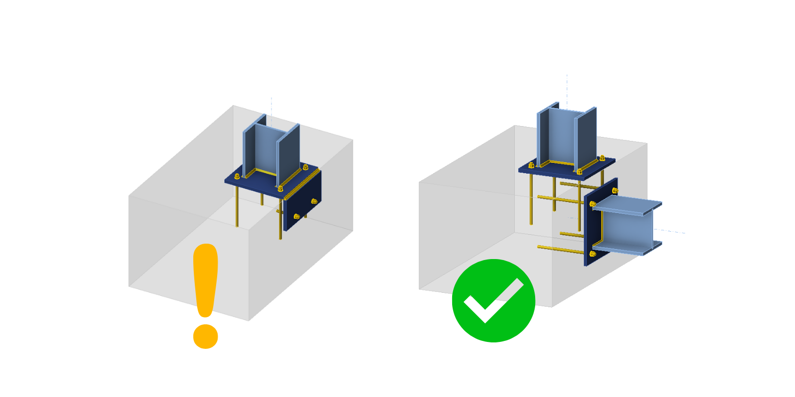
În general, importul forțelor care acționează pe placa de bază prin contact cu o altă placă metalică nu este suportat. Aceasta se aplică atât contactului de tip muchie-suprafață, cât și celui de tip suprafață-suprafață. Citiți mai multe în acest articol.
Ancorare prin element
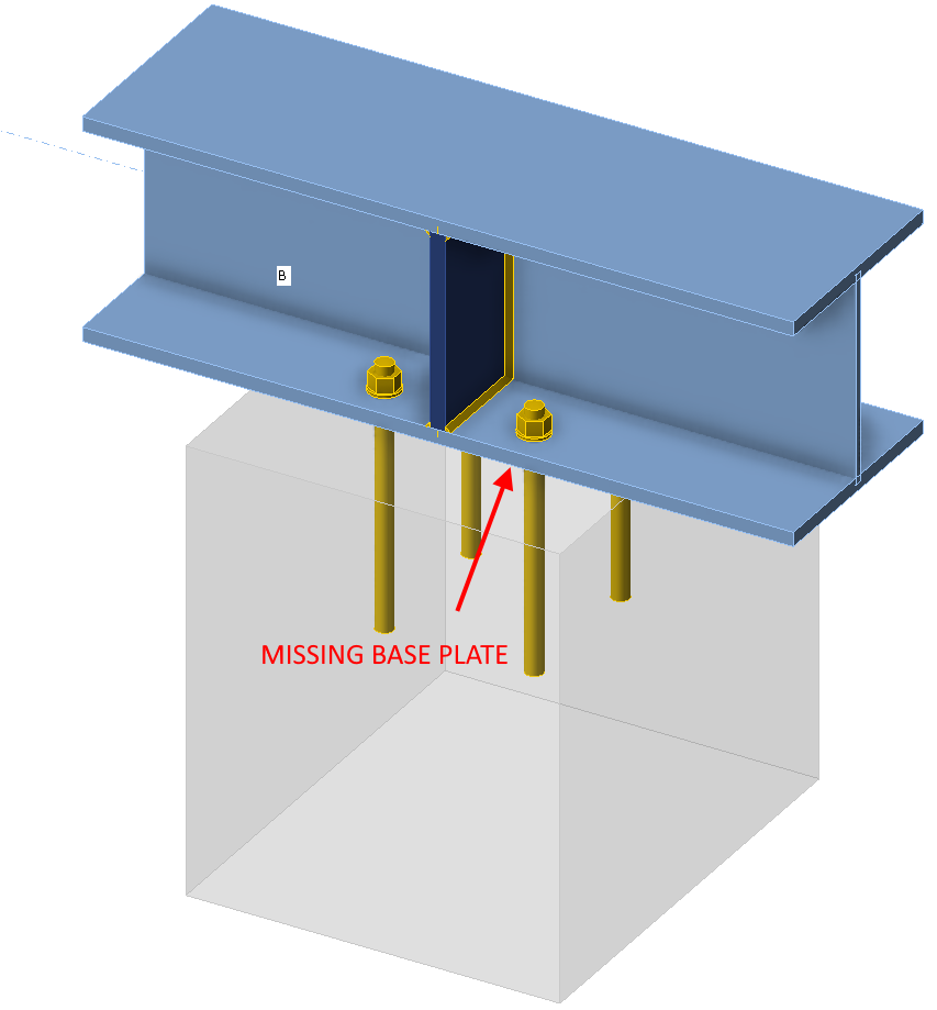
Doar modelele ancorate prin intermediul plăcii de bază pot fi importate corect în aplicația Detail. Pentru modelele în care elementele sunt conectate direct la blocurile de beton, placa de conectare a elementului cu ancore este importată fără încărcări.
Greutatea proprie nu este adăugată automat
Greutatea proprie nu este calculată/adăugată automat. Aceasta trebuie inclusă manual în proiect pentru Detail. Acest lucru poate afecta în principal verificarea ancorării la fundații, unde neluarea în considerare a greutății proprii ar putea duce la răsturnarea fundației, după cum s-a menționat în paragraful de mai sus.
Tipuri de ancorare nesuportate pentru export
Ancorele cu cârlig nu sunt suportate în Detail. În schimb, în fișierul exportat va fi utilizată o placă tip șaibă.
Placa tip șaibă este modelată ca un element placă-coajă atașat direct la tija ancorei, transferând încărcarea către beton exclusiv prin contact de compresiune. Placa în sine este modelată liniar, fără plasticitate, și nu este supusă verificărilor de rezistență. Deoarece tija are rezistență la aderență zero, întreaga încărcare este transferată betonului prin placa tip șaibă. Mai multe informații despre tipurile de ancore pot fi găsite în articolul: Definiția ancorei individuale.
Combinații nesuportate pentru tipurile de ancore
Aplicația Detail nu suportă combinarea dornurilor cu cap sau a armăturii cu alte tipuri de ancore. Aceste tipuri de ancore nu vor fi incluse în rezultat. Mai multe informații despre opțiunile plăcilor pot fi găsite în articolul: Opțiuni plăci de ancorare.
Combinarea încărcărilor importate cu încărcările introduse de utilizator
Încărcările importate și încărcările introduse de utilizator nu pot fi combinate într-un singur model. Din motivele descrise în Fundamente teoretice. Ancorele sunt importate deconectate de plăcile de bază. Dacă creați un caz de încărcare definit de utilizator, este evident că încărcarea nu va fi transferată corect.
Soluție de lucru: Copiați elementul de Proiect importat, ștergeți toate încărcările importate, interconectați toate ancorele cu placa de bază și apoi puteți introduce cazul de încărcare definit de utilizator.
Mai multe blocuri de beton
Doar un singur bloc de beton este suportat în Detail. Cu toate acestea, blocul de beton poate fi modificat folosind Volumul negativ, Planul de tăiere și operația de tăiere. Astfel, este posibil să se modeleze forme mai complexe, cum ar fi socluri, extensii de fundații continue, ancorare lângă goluri etc.
Este de asemenea posibil să se importe două blocuri de beton independente din Connection, care sunt importate în Detail ca două entități de model ce pot fi modificate ulterior folosind operația de tăiere.
Mai mult de o placă de bază într-un singur bloc
Exportul mai multor plăci de bază într-un singur bloc este suportat, deși nu se recomandă importul așa-numitei ancorări de margine.
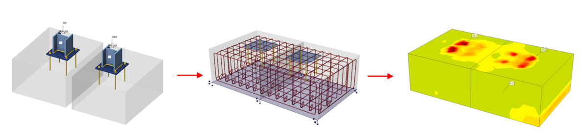
În aplicația Connection, betonul este modelat într-un mod simplificat folosind subgradeul Winkler. Pe de altă parte, modelul părții metalice de deasupra blocului de beton este modelat în detaliu, inclusiv plasticitatea materialelor. Pentru o verificare mai detaliată a betonului armat de sub placa de bază, este posibil să se exporte placa de bază, ancorele și încărcările în aplicația Detail. Acolo, betonul este modelat plastic.
Ancorele sunt exportate deconectate axial, iar încărcarea dintre ele este înlocuită de o pereche de forțe egale și opuse (tocmai din cauza lipsei de rigiditate a părții metalice de deasupra plăcii de bază). Prin urmare, nu este posibil ca forțele axiale din ancore să se modifice dacă stratul de acoperire din colțul blocului de beton devine plastic. În mod similar, sudurile plăcilor de bază sunt exportate deconectate, conexiunea fiind înlocuită de forțe egale și opuse. Prin urmare, nu poate exista nicio modificare a tensiunii în sudură în cazul plastificării colțului de beton.
Rezultă că după export, deși toate forțele care acționează pe plăcile de bază sunt în echilibru, condițiile de deformare nu vor fi îndeplinite.
Se aplică versiunii curente 25.1.2. Poate diferi în versiunile anterioare, deoarece lucrăm treptat la eliminarea acestor limitări. Puteți găsi mai multe informații despre fiecare versiune în notele de lansare.