Verificarea conform codului a ancorelor conform standardelor australiene
Forțele din ancore, inclusiv efectul de pârghie, sunt determinate prin analiza cu elemente finite, dar rezistențele sunt verificate conform prevederilor AS 5216.
Verificarea ancorelor se efectuează conform AS 5216:2018. Deși codul nu prevede în mod specific unele formule pentru ancorele turnate in situ, formulele sunt identice cu cele din SA TS 101:2015, unde ancorele turnate in situ sunt menționate explicit. Betonul fisurat sau nefisurat poate fi selectat în configurarea codului. Betonul fisurat este considerat în mod conservativ ca valoare implicită. Verificarea conului de beton la întindere și forfecare poate fi ignorată în configurarea codului, ceea ce înseamnă că forța este considerată a fi transferată prin armătură. Utilizatorul primește informații privind mărimea acestei forțe. Datorită utilizării rezistenței conului de beton în formula de verificare la smulgere prin pârghie, această verificare este de asemenea ignorată.
Următoarele verificări ale ancorelor solicitate la întindere nu sunt furnizate și trebuie verificate utilizând informațiile din Specificația Tehnică de Produs relevantă (testare conform AS 5216:2018: Anexa A):
- Cedarea prin smulgere a dispozitivului de fixare (pentru ancore mecanice post-instalate) – AS 5216:2018: 6.2.4,
- Cedarea combinată prin smulgere și con de beton (pentru ancore adezive post-instalate) – AS 5216:2018: 6.2.5,
- Cedarea prin despicare a betonului – AS 5216:2018: 6.2.6.
Cedarea prin suflare a betonului este furnizată doar pentru ancorele cu plăci tip șaibă.
Cedarea oțelului la întindere
Cedarea oțelului la întindere este verificată conform Cl. 6.2.2:
\[ ϕ_{Ms} N_{tf} = ϕ_{Ms} A_s f_{uf} \]
unde:
- \( ϕ_{Ms} = \frac{5 f_{yf}}{6 f_{uf}} \le 1/1.4 \) – factor de capacitate pentru cedarea oțelului la întindere (Tabelul 3.2.4)
- As – aria secțiunii transversale la întindere a unui șurub, conform AS 1275
- fuf – rezistența minimă la întindere a șurubului, conform AS 4100 – Tabelul 9.3.1
Cedarea conului de beton
Cedarea conului de beton este verificată conform Cl. 6.2.3 și este furnizată pentru grupul de ancore (acolo unde este aplicabil). Rezistența caracteristică a dispozitivelor de fixare solicitate la întindere dintr-un grup sau a unui singur dispozitiv de fixare este:
\[ ϕ_{Mc} N_{Rk,c} = ϕ_{Mc} N_{Rk,c}^0 \left ( \frac{A_{c,N}}{A^0_{c,N}} \right ) \psi_{s,N} \psi_{re,N} \psi_{ec,N} \psi_{M,N} \]
unde:
- ϕMc – factor de capacitate pentru modurile de cedare ale ancorelor legate de beton, editabil în configurarea codului; valoarea recomandată este 1/1.5 (Tabelul 3.2.4)
- \( N_{Rk,c}^0 = k_1 \sqrt{f'_c} h_{ef}^{1.5} \) – rezistența caracteristică a unui dispozitiv de fixare, departe de efectele dispozitivelor de fixare adiacente sau ale marginilor elementului de beton – Cl. 6.2.3.2
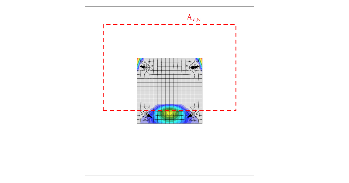
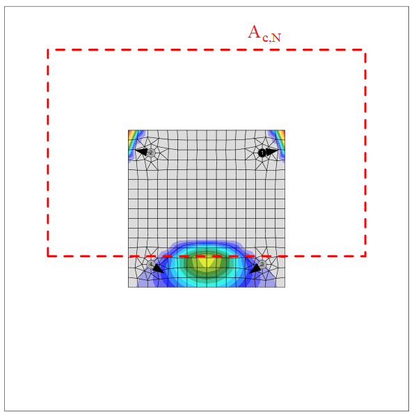
- Ac,N – aria proiectată reală a conului de cedare al dispozitivului de fixare, limitată de dispozitivele de fixare adiacente și de marginile elementului de beton – Cl. 6.2.3.3
- Ac,N0 = scr,N2 – aria proiectată de referință a unui singur dispozitiv de fixare cu o distanță față de margine cel puțin egală cu 1.5 hef – Cl. 6.2.3.3
- \( \psi_{s,N} = 0.7 + 0.3 \frac{c}{c_{cr,N}} \le 1 \) – parametru legat de distribuția tensiunilor în beton datorită proximității dispozitivului de fixare față de marginea elementului de beton – Cl. 6.2.3.4
- \( \psi_{re,N} = 0.5 + \frac{h_{ef}}{200} \le 1 \)– parametru care ține cont de efectul de exfoliere a stratului de acoperire – Cl. 6.2.3.5
- \( \psi_{ec,N} = \frac{1}{1+2 e_N / s_{cr,N}} \le 1 \) – parametru care ține cont de excentricitatea forței rezultante într-un grup de dispozitive de fixare – Cl. 6.2.3.6
- \( \psi_{M,N} = 2- \frac{2 z}{3 h_{ef}} \ge 1 \) – parametru care ține cont de efectul forței de compresiune dintre placa de prindere și beton – Cl. 6.2.3.7; acest parametru este egal cu 1 dacă c < 1.5 hef sau dacă raportul dintre forța de compresiune (inclusiv compresiunea datorată încovoierii) și suma forțelor de întindere din ancore este mai mic de 0.8
- \item k1 – parametru; pentru ancorele turnate in situ (tip ancoră – plăci tip șaibă) k1 = kcr,N = 8.9 pentru beton fisurat și k1 = kucr,N = 12.7 pentru beton nefisurat; pentru ancore post-instalate (tip ancoră – drepte) k1 = kcr,N = 7.7 pentru beton fisurat și k1 = kucr,N = 11.0 pentru beton nefisurat
- scr,N = 2 ccr,N = 3 hef – distanța dintre dispozitivele de fixare
- ccr,N = 1.5 hef – distanța caracteristică față de margine
- hef – adâncimea efectivă de încastrare a dispozitivului de fixare; în cazul unui element de beton îngust, se aplică Cl. 6.2.3.8 și\( h'_{ef} = \max \left ( \frac{c_{max}}{c_{cr,N}}h_{ef}; \, \frac{s_{max}}{s_{cr,N}}h_{ef} \right ) \)
- z – brațul interior al forței
- c – cea mai mică distanță față de margine
Aria conului de rupere a betonului pentru un grup de ancore solicitate la întindere care formează un con comun de beton, Ac,N, este indicată prin linie roșie întreruptă.
Conform Cl. 6.2.8, armătura suplimentară poate fi utilizată pentru a transfera forțele care provoacă cedarea conului de beton. O astfel de armătură trebuie proiectată în conformitate cu AS 3600.
Cedarea prin smulgere
Cedarea prin smulgere este verificată pentru dispozitivele de fixare cu cap turnat in situ (tip ancoră – placă tip șaibă) conform SA TS 101:2015 – Cl. 6.2.3:
\[ ϕ_{Mc} N_{Rk,p} = k_1 A_h f'_c \]
- ϕMc – factor de capacitate pentru modurile de cedare ale ancorelor legate de beton, editabil în configurarea codului; valoarea recomandată este 1/1.5 (Tabelul 3.2.4)
- k1 – parametru legat de starea betonului; pentru beton fisurat k1 = 8.0, pentru beton nefisurat k1 = 11.2
- Ah – aria capului portant al dispozitivului de fixare; pentru placă tip șaibă circulară \( A_h = \frac{\pi}{4} \left ( d_h^2 - d^2 \right \)$, pentru placă tip șaibă dreptunghiulară \( A_h = a_{wp}^2 - \frac{\pi}{4} d^2 \)
- dh ≤ 6 th + d – diametrul capului dispozitivului de fixare
- th – grosimea capului dispozitivului de fixare cu cap
- d – diametrul tijei dispozitivului de fixare
- awp – lungimea laturii plăcii tip șaibă dreptunghiulare
- f'c – rezistența caracteristică la compresiune a betonului
Cedarea prin smulgere pentru ancorele cu cap altele decât cele turnate in situ nu este calculată, iar rezistența trebuie garantată de producător sau determinată prin testare și evaluare în conformitate cu Anexa A.
Nici rezistența la cedarea prin despicare în timpul instalării (Cl. 6.2.6.1), nici cea datorată încărcării (Cl. 6.2.6.2) nu sunt furnizate și trebuie garantate de producător sau determinate prin testare și evaluare în conformitate cu Anexa A.
Cedarea prin suflare
Cedarea prin suflare este verificată pentru ancorele cu cap (tip ancoră – șaibă) cu distanța față de margine c ≤ 0.5 hef conform Cl. 6.2.7. Ancorele sunt tratate ca grup dacă distanța dintre ele în apropierea marginii este s ≤ 4 c1. Ancorele cu coadă de rândunică pot fi verificate în același mod, dar valoarea Ah este necunoscută în software. Cedarea prin suflare a ancorelor cu coadă de rândunică poate fi determinată prin selectarea plăcii tip șaibă cu dimensiunea corespunzătoare.
\[ ϕ_{Mc} N_{Rk,cb} = ϕ_{Mc} N_{Rk,cb}^0 \frac{A_{c,Nb}}{A_{c,Nb}^0} \psi_{s,Nb} \psi_{g,Nb} \psi_{ec,Nb} \]
unde:
- ϕMc – factor de capacitate pentru modurile de cedare ale ancorelor legate de beton, editabil în configurarea codului; valoarea recomandată este 1/1.5 (Tabelul 3.2.4)
- \( N_{Rk,cb}^0 = k_5 c_1 \sqrt{A_h} \sqrt{f'_c} \) – rezistența caracteristică a unui singur dispozitiv de fixare departe de efectele dispozitivelor de fixare adiacente și ale marginilor elementului de beton – Cl. 6.2.7.2
- Ac,Nb – aria proiectată reală pentru dispozitivul de fixare, limitată de marginile elementului de beton (c2 ≤ 2 c1), de prezența dispozitivelor de fixare adiacente (s ≤ 4 c1) sau de grosimea elementului – Cl. 6.2.7.3
- Ac,Nb0 = (4 c1)2 – aria proiectată de referință a unui singur dispozitiv de fixare cu distanța față de margine egală cu c1 – Cl. 6.2.7.3
- \( \psi_{s,Nb} = 0.7+0.3 \frac{c_2}{2 c_1} \le 1 \) – parametru care ține cont de perturbarea tensiunilor în beton datorită proximității dispozitivului de fixare față de un colț al elementului de beton – Cl. 6.2.7.4
- \( \psi_{g,Nb} = \sqrt{n} + (1-\sqrt{n}) \frac{s_2}{4c_1} \ge 1 \) – parametru care ține cont de efectul de grup – Cl. 6.2.7.5
- \( \psi_{ec,Nb} = \frac{1}{1+2 e_N / s_{cr,Nb}} \le 1 \) – parametru care ține cont de excentricitatea încărcării pe un grup de dispozitive de fixare – Cl. 6.2.7.6
- k5 – parametru legat de starea betonului; pentru beton fisurat k5 = 8.7, pentru beton nefisurat k5 = 12.2
- c1 – distanța față de margine a dispozitivului de fixare în direcția 1, către cea mai apropiată margine
- c2 – distanța față de margine a dispozitivului de fixare perpendicular pe direcția 1, care este cea mai mică distanță față de margine într-un element îngust cu mai multe distanțe față de margine
- Ah – aria capului portant al dispozitivului de fixare; pentru placă tip șaibă circulară \( A_h = \frac{\pi}{4} \left ( d_h^2 - d^2 \right \), pentru placă tip șaibă dreptunghiulară \( A_h = a_{wp}^2 - \frac{\pi}{4} d^2 \)
- f'c – rezistența caracteristică la compresiune a betonului
- n – numărul de dispozitive de fixare dintr-un rând paralel cu marginea elementului de beton
- s2 – distanța dintre dispozitivele de fixare dintr-un grup, perpendicular pe direcția 1
- scr,Nb = 4 c1 – distanța necesară pentru ca un dispozitiv de fixare să dezvolte rezistența sa caracteristică la întindere împotriva cedării prin suflare
Cedarea oțelului la forfecare
Cedarea oțelului la forfecare este determinată conform Cl. 7.2.2. Se presupune că ancora este realizată dintr-o tijă filetată cu aceleași proprietăți de material ca și șuruburile.
Forță tăietoare fără braț de pârghie
Forța tăietoare fără braț de pârghie este considerată dacă este selectată opțiunea stand-off – direct. Se presupune că dispozitivele de fixare sunt din oțel ductil și factorul k7 = 1. Fiecare dispozitiv de fixare este verificat separat. Rezistența este determinată conform AS 5216 – Cl. 7.2.2.2 și AS 4100 – Cl. 9.2.2.1:
\[ ϕ_{Ms} V_{Rk,s} = ϕ_{Ms} 0.62 f_{uf} A \]
unde:
- \( ϕ_{Ms} = f_{yf} / f_{uf} \le 0.8 \) când fuf ≤ 800 MPa și fyf / fuf ≤ 0.8; ϕMs = 2/3 în caz contrar – factor de capacitate pentru cedarea oțelului la forfecare (Tabelul 3.2.4)
- fuf – rezistența minimă la întindere a șurubului, conform AS 4100 Tabelul 9.2.1
- A – aria unui șurub egală fie cu Ac, fie cu Ao, care reprezintă aria secțiunii transversale la diametrul minim al șurubului, conform AS 1275, respectiv aria nominală a tijei netede a șurubului
Pentru dispozitivele de fixare cu hef / d < 5 în beton cu f'c < 20 MPa, VRk,s se înmulțește cu un factor egal cu 0.8.
Forță tăietoare cu braț de pârghie
Rezistența la forfecare a oțelului cu braț de pârghie este calculată conform Cl. 7.2.2.3:
\[ ϕ_{Ms} V_{Rk,s,M} = ϕ_{Ms} \frac{\alpha_M M_{Rk,s}}{l_a} \]
unde:
- \( ϕ_{Ms} = f_{yf} / f_{uf} \le 0.8 \) când fuf ≤ 800 MPa și fyf / fuf ≤ 0.8; ϕMs = 2/3 în caz contrar – factor de capacitate pentru cedarea oțelului la forfecare (Tabelul 3.2.4)
- αM = 2 – parametru care ține cont de gradul de încastrare; se presupune că placa de prindere este împiedicată să se rotească – Cl. 4.2.2.4
- \( M_{Rk,s} = M_{Rk,s}^0 \left ( 1- \frac{N^*}{ϕ_{Ms} N_{Rk,s}} \right ) \) – rezistența caracteristică la încovoiere a dispozitivului de fixare influențată de forța axială
- la = a3 + e1 – lungimea brațului de pârghie
- a3 = 0.5 d – distanța dintre punctul presupus de încastrare al dispozitivului de fixare solicitat la forfecare și suprafața betonului
- e1 = tg + tfix / 2 – excentricitatea forței tăietoare aplicate față de suprafața betonului, neglijând grosimea stratului de nivelare din mortar
- tg – grosimea stratului de mortar
- tfix – grosimea plăcii de bază
- d – diametrul nominal al dispozitivului de fixare
- N* – forța de întindere de calcul
- ϕMs NRk,s – rezistența la întindere a unui dispozitiv de fixare la cedarea oțelului
- MRk,s0 = 1.2 Wel fuf – rezistența caracteristică la încovoiere a dispozitivului de fixare – ETAG 001 – Anexa C
- Wel = π d3 / 32 – modulul de rezistență elastic al dispozitivului de fixare; diametrul redus la filet, \( d_s = \sqrt{\frac{4 A_s}{\pi}} \), este utilizat în locul diametrului nominal, d, dacă este selectată opțiunea Planul de forfecare în filet
Cedarea betonului la margine
Cedarea betonului la margine este verificată conform Cl. 7.2.3. Dacă conurile de beton ale dispozitivelor de fixare se intersectează, acestea sunt verificate ca grup. Se verifică marginile în direcția forței tăietoare. Se presupune că întreaga forță de la o placă de bază este transferată de dispozitivul de fixare din apropierea marginii verificate.
\[ ϕ_{Mc} V_{Rk,c} = ϕ_{Mc} V_{Rk,c}^0 \frac{A_{c,V}}{A_{c,V}^0} \psi_{s,V} \psi_{h,V} \psi_{ec,V} \psi_{\alpha,V} \psi_{re,V} \]
unde:
- ϕMc – factor de capacitate pentru modurile de cedare ale ancorelor legate de beton, editabil în configurarea codului; valoarea recomandată este 1/1.5 (Tabelul 3.2.4)
- \( V_{Rk,c}^0 = k_9 d^{\alpha} l_f^{\beta} \sqrt{f'_c} c_1^{1.5} \) – valoarea inițială a rezistenței caracteristice la forfecare a dispozitivului de fixare – Cl. 7.2.3.2
- Ac,V – aria reală a corpului idealizat de rupere a betonului – Cl. 7.2.3.3
- Ac,V0 = 4.5 c12 – aria proiectată de referință a conului de cedare – Cl. 7.2.3.3
- \( psi_{s,V} = 0.7 + 0.3 \frac{c_2}{1.5 c_1} \le 1 \) – parametru care ține cont de perturbarea distribuției tensiunilor în elementul de beton – Cl. 7.2.3.4
- \( \psi_{h,V} = \left ( \frac{1.5 c_1}{h} \right ) ^{0.5} \ge 1 \) – parametru care ține cont de influența grosimii elementului – Cl. 7.2.3.5
- \( \psi_{ec,V} = \frac{1}{1+2 e_V / (3c_1)} \le 1 \) – parametru care ține cont de excentricitatea forței rezultante într-un grup de dispozitive de fixare – Cl. 7.2.3.6
- \( \psi_{\alpha,V} = \sqrt{\frac{1}{(\cos \alpha_V)^2 + (0.5 \sin \alpha_V)^2}} \ge 1 \) – parametru care ține cont de unghiul forței aplicate – Cl. 7.2.3.7
- ψre,V = 1 – parametru care ține cont de efectul de exfoliere a stratului de acoperire – Cl. 7.2.3.8; se presupune că nu există armătură la margine sau etrieri
- k9 – parametru care ține cont de starea betonului; pentru beton fisurat k9 = 1.7, pentru beton nefisurat k9 = 2.4
- d – diametrul nominal al dispozitivului de fixare
- \( \alpha = 0.1 \left ( \frac{l_f}{c_1} \right ) ^{0.5} \)
- \( \beta = 0.1 \left ( \frac{d}{c_1} \right ) ^{0.2} \)
- lf = hef ≤ 12 d unde d ≤ 24 mm; lf = hef ≤ max (8 d, 300 mm) unde d > 24 mm – parametru legat de lungimea dispozitivului de fixare
- f'c – rezistența caracteristică la compresiune pe cilindru a betonului la 28 de zile
- c1 – distanța față de marginea investigată a dispozitivului de fixare; conform Cl. 7.2.3.9, pentru un element îngust, c2,max < 1.5 c1, considerat și subțire, h < 1.5 c1, se utilizează c'1 în ecuațiile anterioare în locul lui c1; valoarea redusă c'1 = max (c2,max / 1.5, h/ 1.5, sc,max / 3)
- c2 – cea mai mică distanță față de margine a dispozitivului de fixare în direcția perpendiculară pe marginea investigată
- h – grosimea elementului de beton
- eV – excentricitatea forței tăietoare rezultante care acționează asupra unui grup de dispozitive de fixare față de centrul de greutate al dispozitivelor de fixare solicitate la forfecare
- αV – unghiul dintre forța aplicată pe dispozitivul de fixare sau grupul de dispozitive de fixare și direcția perpendiculară pe marginea liberă considerată, 0° < αV < 90°
- hef – adâncimea efectivă de încastrare a dispozitivului de fixare
Conform Cl. 6.2.8, armătura suplimentară poate fi utilizată pentru a transfera forțele care provoacă cedarea betonului la margine și/sau cedarea prin pârghie a betonului. O astfel de armătură trebuie proiectată în conformitate cu AS 3600.
Cedarea prin pârghie a betonului
Cedarea prin pârghie a betonului este verificată conform Cl. 7.2.4. Se presupune că toate ancorele de la o placă de bază sunt solicitate la forfecare, iar rezistența la rupere a conului de beton, NRk,c, utilizată în calcul, este calculată cu ipoteza că toate ancorele sunt solicitate la întindere fără nicio excentricitate. Nu se consideră armătură suplimentară.
\[ ϕ_{Mc} V_{Rk,cp} = ϕ_{Mc} k_8 N_{Rk,c} \]
unde:
- ϕMc – factor de capacitate pentru modurile de cedare ale ancorelor legate de beton, editabil în configurarea codului; valoarea recomandată este 1/1.5 (Tabelul 3.2.4)
- k8 – parametru publicat în Raportul de Evaluare, conform ETAG 001 – Anexa C; pentru hef < 60 mm, k8 = 1 și pentru hef ≥ 60 mm, k8 = 2
- NRk,c – rezistența caracteristică a conului de beton pentru un singur dispozitiv de fixare sau pentru un dispozitiv de fixare dintr-un grup
Solicitare combinată la întindere și forfecare
Rezistența unui dispozitiv de fixare solicitat la întindere și forfecare combinate este determinată conform Capitolului 8.
Cedarea oțelului
Evaluarea comportamentului sub solicitare combinată la întindere și forfecare a dispozitivului de fixare se bazează pe AS 4100:
\[ \left ( \frac{N^*}{ϕ_{Ms} N_{Rk,s}} \right ) ^2 + \left ( \frac{V^*}{ϕ_{Ms} V_{Rk,s}} \right ) ^2 \le 1.0 \]
Cedarea betonului
Modurile de cedare altele decât cedarea oțelului sunt verificate conform Cl. 8.2.1:
\[ \left ( \frac{N^*}{ϕ_{Mc} N_{Rk,i}} \right ) ^{1.5} + \left ( \frac{V^*}{ϕ_{Mc} V_{Rk,i}} \right ) ^{1.5} \le 1.0 \]
unde:
- N* – forța de întindere de calcul aplicată unui singur dispozitiv de fixare sau unui grup
- V* – forța tăietoare de calcul aplicată unui singur dispozitiv de fixare sau unui grup
- NRk,i – rezistența caracteristică la întindere a dispozitivului de fixare sau grupului pentru modul de cedare „i"
- VRk,i – rezistența caracteristică la forfecare a dispozitivului de fixare sau grupului pentru modul de cedare „i"
- \( ϕ_{Ms} = \frac{5 f_{yf}}{6 f_{uf}} \) – factor de capacitate pentru cedarea oțelului la întindere (Tabelul 3.2.4)
- ϕMs = fyf / fuf ≤ 0.8 când fuf ≤ 800 MPa și fyf / fuf ≤ 0.8; ϕMs = 2/3 în caz contrar – factor de capacitate pentru cedarea oțelului la forfecare (Tabelul 3.2.4)
- ϕMc – factor de capacitate pentru modurile de cedare ale ancorelor legate de beton, editabil în configurarea codului; valoarea recomandată este 1/1.5 (Tabelul 3.2.4)
Ancore cu stand-off
Ancorele cu stand-off sunt proiectate ca elemente de tip grindă conform AS 4100 cu factorii de capacitate ai șuruburilor. Lungimea presupusă a elementului este suma înălțimii golului, jumătate din grosimea diametrului nominal și jumătate din grosimea plăcii de bază. Ancorele cu stand-off sunt de obicei verificate ca etapă de execuție înainte de injectare.
Capacitatea la încovoiere
Capacitatea la încovoiere este determinată conform AS 4100, Cl. 5.1.
M* ≤ ϕ Ms
unde:
- M* – momentul încovoietor care acționează asupra ancorului, determinat prin metoda elementelor finite
- ϕ = 0.8 – factor de capacitate pentru șuruburi
- Ms = fy Ze – capacitatea de moment a secțiunii la încovoiere
- fy – limita de curgere a ancorului
- Ze = min {S, 1.5 · Z} – modulul de rezistență efectiv al secțiunii – Cl. 5.2.3
- \( S = \frac{d^3}{6} \) – modulul de rezistență plastic al secțiunii; dacă este selectată opțiunea Planul de forfecare în filet, diametrul nominal d este înlocuit cu diametrul redus la filet, ds
- \( Z = \frac{1}{32} \pi d^3 \) – modulul de rezistență elastic al secțiunii; dacă este selectată opțiunea Planul de forfecare în filet, diametrul nominal d este înlocuit cu diametrul redus la filet, ds
Capacitatea la forfecare
Capacitatea la forfecare este determinată conform AS 4100, Cl. 5.11.
V* ≤ ϕ Vw
unde:
- V* – forța tăietoare de calcul
- ϕ = 0.8 – factor de capacitate pentru șuruburi
- Vw = 0.6 fy Aw – capacitatea nominală la curgere prin forfecare – Cl. 5.11.4
- fy – limita de curgere a ancorului
- Aw = 0.844 As – aria de forfecare
- As – aria secțiunii transversale la întindere a unui șurub, conform AS 1275
Capacitatea la compresiune axială
Capacitatea la compresiune axială este determinată conform AS 4100, Cl. 6. Flambajul este luat în considerare conform Cl. 6.3:
N* ≤ ϕ Nc
unde:
- N* – forța de compresiune de calcul
- ϕ = 0.8 – factor de capacitate pentru șuruburi
- Nc = αc Ns ≤ Ns – capacitatea nominală a elementului – Cl. 6.3.3
- Ns = kf As fy – capacitatea nominală a secțiunii – Cl. 6.2
- fy – limita de curgere a ancorului
- le = ke l – lungimea de flambaj – Cl. 6.3.2
- ke = 2 – factorul lungimii efective a elementului; se presupune în mod conservativ că ancora este încastrată la bază și articulată la vârf, ca element cu deplasare laterală
- l = lgap + d / 2 + tp / 2 – lungimea presupusă a elementului
- lgap – înălțimea golului
- d – diametrul nominal al șurubului
- tp – grosimea plăcii de bază
- \( \alpha_c = \xi \left \{ 1 - \sqrt{1- \left ( \frac{90}{\xi \lambda} \right )^2 } \right \} \) – factorul de reducere a zveltețe a elementului comprimat – Cl. 6.3.3
- \( \xi = \frac{\left( \frac{\lambda}{90} \right)^2 + 1 + \eta}{2 \left( \frac{\lambda}{90} \right)^2} \) – factorul elementului comprimat – Cl. 6.3.3
- \( \lambda = \lambda_n + \alpha_a \alpha_b \) – raportul de zveltețe – Cl. 6.3.3
- \( \eta = 0.00326 (\lambda-13.5) \) – factorul de imperfecțiune al elementului comprimat – Cl. 6.3.3
- \( \lambda_n = \frac{l_e}{r} \sqrt{k_f} \sqrt{\frac{f_y}{250}} \) – zveltețea modificată a elementului comprimat – Cl. 6.3.3
- kf = 1 – factorul de formă – Cl. 6.2.2
- \( r = \sqrt{\frac{I_s}{A_s}} \) – raza de girație
- \( I_s = \frac{1}{64} \pi d_s^4 \) – momentul de inerție
- As – aria secțiunii transversale la întindere a unui șurub, conform AS 1275
- \( d_s = \sqrt{\frac{4 A_s}{\pi}} \) – diametrul redus la filet
- \( \alpha_a = \frac{2100 (\lambda_n - 13.5)}{\lambda_n^2 - 15.3 \lambda_n + 2050} \) – factorul elementului comprimat – Cl. 6.3.3
- αb = 0.5 – constanta de secțiune a elementului comprimat - Tabelul 6.3.3
Capacitatea la întindere axială
Capacitatea la întindere axială este determinată conform AS 4100, Cl. 7:
N* ≤ ϕ Nt
unde:
- N* – forța de întindere de calcul
- ϕ = 0.8 – factor de capacitate pentru șuruburi
- Nt = As fy – capacitatea nominală a secțiunii unui șurub la întindere – Cl. 7.2
- As – aria secțiunii transversale la întindere a unui șurub, conform AS 1275
- fy – limita de curgere a ancorului
Interacțiunea solicitărilor
Dacă o ancoră cu stand-off este solicitată de o forță tăietoare și o forță de compresiune, se efectuează verificarea interacțiunii solicitărilor:
\[ \frac{N^*}{\phi N_c} + \frac{M^*}{\phi M_s} \le 1 \]
unde:
- N* – forța de compresiune de calcul
- ϕ = 0.8 – factor de capacitate pentru șuruburi
- Nc – rezistența la compresiune
- M* – momentul încovoietor de calcul datorat forței tăietoare pe brațul de pârghie
- Ms – rezistența la încovoiere
În plus, se efectuează verificările cedării oțelului la forfecare și ale cedărilor betonului la forfecare (cedarea betonului la margine, cedarea prin pârghie a betonului).
Dacă o ancoră cu stand-off este solicitată de o forță tăietoare și o forță de întindere, se efectuează verificarea interacțiunii solicitărilor:
\[ \frac{N_{tf}^*}{\phi N_{t}} + \frac{M^*}{\phi M_s} \le 1 \]
unde:
- N*tf – forța de întindere de calcul
- ϕ = 0.8 – factor de capacitate pentru șuruburi
- Nt – rezistența la întindere
- M* – momentul încovoietor de calcul datorat forței tăietoare pe brațul de pârghie
- Ms – rezistența la încovoiere
În plus, se efectuează verificările cedării oțelului la forfecare și ale cedărilor betonului datorate întinderii și forfecării.