Kolom voetplaat – Open doorsnede kolom in buiging om sterke as
Beschrijving
Het doel van dit hoofdstuk is de verificatie van de component-gebaseerde eindige elementen methode (CBFEM) van de kolom voetplaat van de stalen open doorsnede kolom belast op druk en buiging om de sterke as met de componentenmethode (CM). De studie is opgesteld voor de afmeting van de kolom, de geometrie en de dikte van de voetplaat. In de studie worden vijf componenten onderzocht: kolomflens en -lijf op druk, beton op druk inclusief grout, voetplaat op buiging, ankers op trek en lassen. Alle componenten zijn ontworpen volgens EN 1993-1-8:2005, EN 1992‑1‑1:2005 en EN 1992‑4.
Verificatie van de weerstand
Een voorbeeld van het ontwerp met de componentenmethode is weergegeven voor de verankering van een stalen kolomdoorsnede HEB 240:
Het betonblok heeft afmetingen a' = 1000 mm, b' = 1500 mm, h = 900 mm en betonkwaliteit C20/25. De voetplaatafmetingen zijn a = 330 mm, b = 440 mm, t = 20 mm en de staalsoort is S235. Ankerbouten zijn 4 × M20, As = 245 mm2, lengte 300 mm, met kopdiameter a = 60 mm en staalsoort 8.8. De groutdikte is 30 mm.
De resultaten van de analytische oplossing kunnen worden weergegeven op een interactiediagram met kenmerkende significante punten. Punt −1 stelt belasting in pure trek voor, en punt 4 stelt de drukweerstand voor. Een gedetailleerde beschrijving van punten 0, 1, 2 en 3 is weergegeven in Fig. 8.2.1; zie (Wald, 1995) en (Wald et al. 2008).
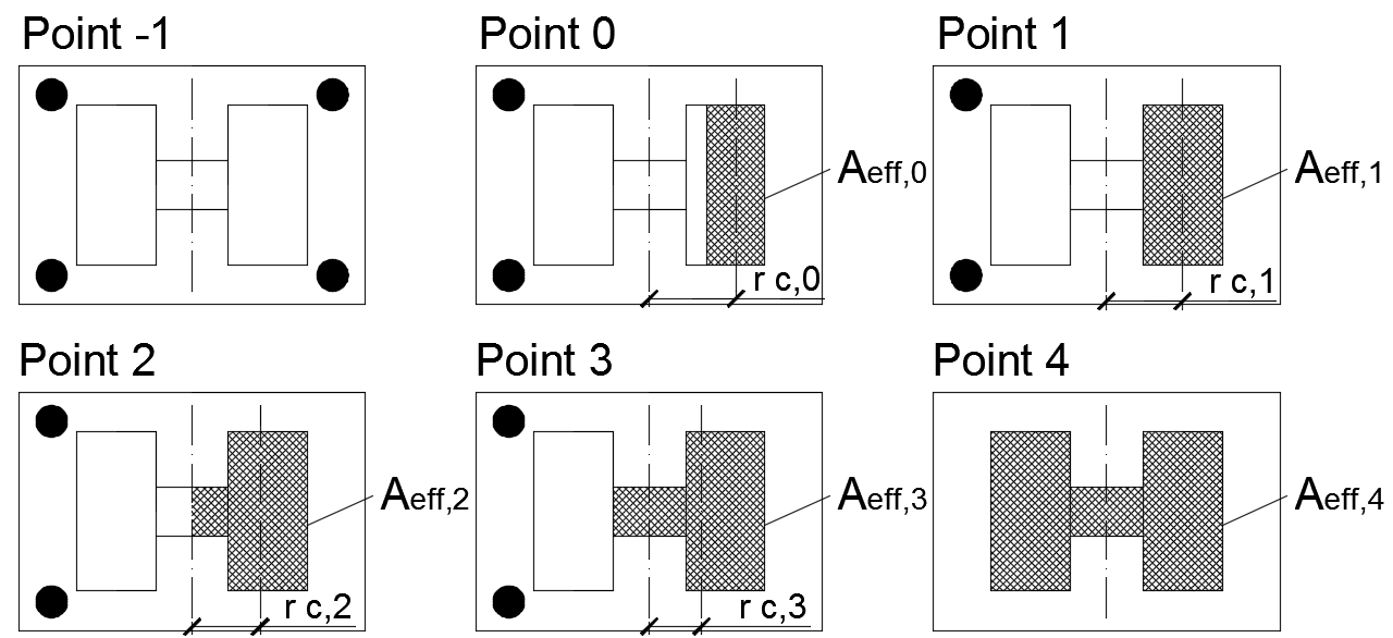
Fig. 8.2.1 Significante punten op het interactiediagram
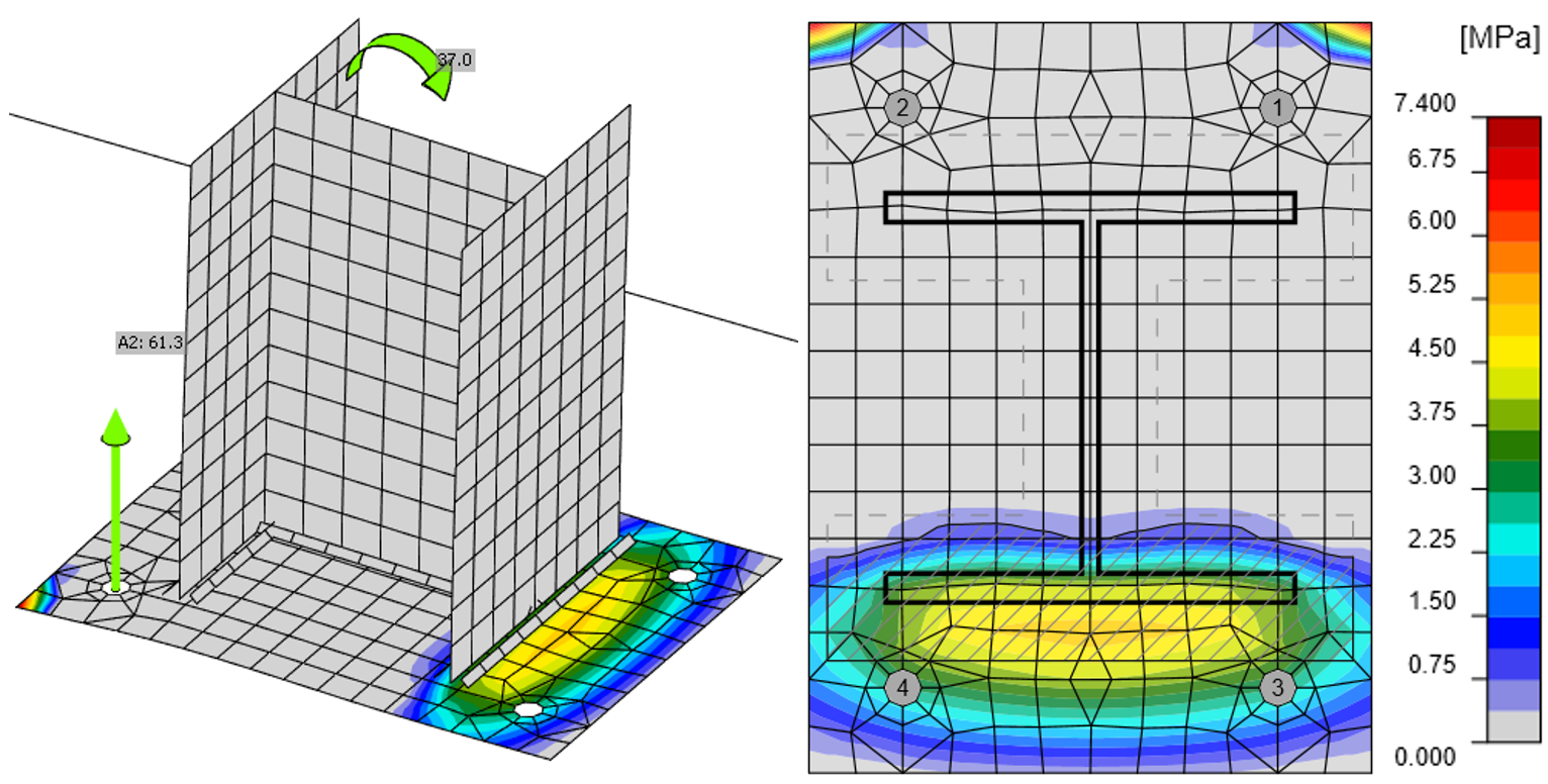
De spanningsverdeling voor punt 0 en 3 verkregen met CBFEM is weergegeven in Fig. 8.2.2 en 8.2.3.

Fig. 8.2.2 Spanning in beton en krachten in ankers voor punt 0 verkregen met CBFEM (vervorm. schaal 10)
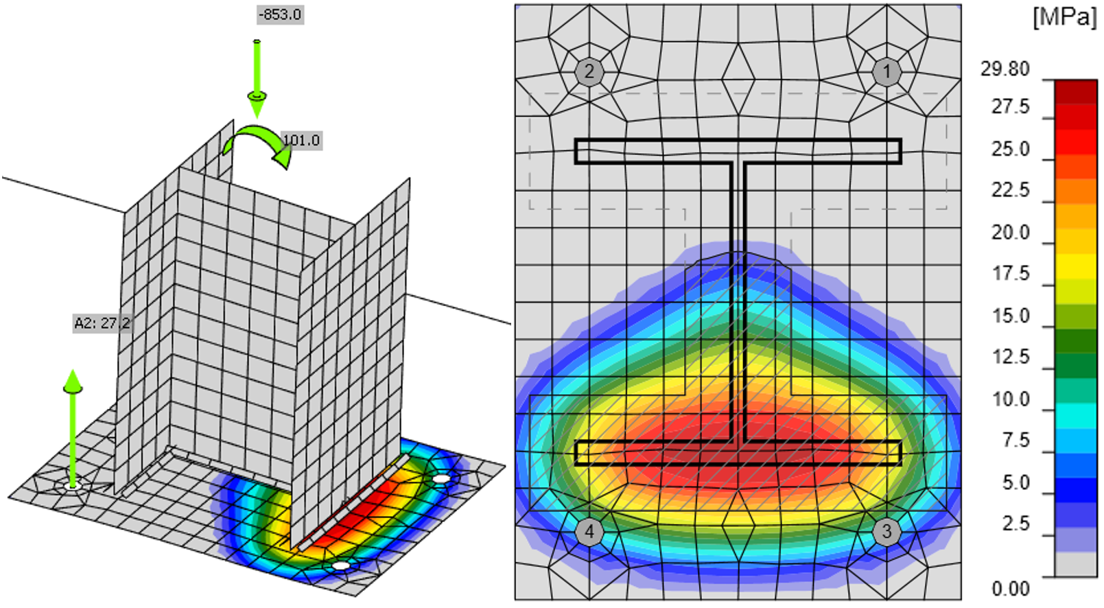
Fig. 8.2.3 Spanning in beton en krachten in ankers voor punt 3 verkregen met CBFEM
(vervorm. schaal 10)
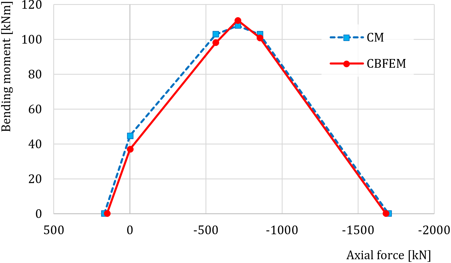
Fig. 8.2.4 Vergelijking van modellen op het interactiediagram
De vergelijking van het interactiediagram verkregen met CBFEM met het interactiediagram berekend volgens de CM is weergegeven in Fig. 8.2.4 en Tab. 8.2.1.
Tab. 8.2.1 Vergelijking van resultaten van het interactiediagram voor HEB 240 via analytische oplossing en via CBFEM
| Analytische oplossing | Resultaten van CBFEM | |||
| Normaalkracht [kN] | Buigweerstand [kNm] | Normaalkracht [kN] | Buigweerstand [kNm] | |
| Punt -1 | 169 | 0 | 150 | 0 |
| Punt 0 | 0 | 45 | 0 | 37 |
| Punt 1 | −564 | 103 | −564 | 98 |
| Punt 2 | −708 | 108 | −708 | 111 |
| Punt 3 | −853 | 103 | −853 | 101 |
| Punt 4 | −1700 | 0 | −1683 | 0 |
Gevoeligheidsstudie
De resultaten van CBFEM werden vergeleken met de resultaten van de componentenmethode. De vergelijking werd gemaakt op basis van de buigmomentweerstand voor het gegeven niveau van de normaalkracht voor elk van de punten van het interactiediagram.
In de gevoeligheidsstudie werden de afmeting van de kolom, de afmetingen van de voetplaat en de afmetingen van het betonblok gevarieerd. De geselecteerde kolomdoorsneden waren HEB 200, HEB 300 en HEB 400. De breedte en lengte van de voetplaat werden gekozen als respectievelijk 100 mm, 150 mm en 200 mm groter dan de kolomdoorsnede; de dikte van de voetplaat was 15 mm, 20 mm en 25 mm. Het betonblok was van kwaliteit C25/30. De hoogte van het betonblok was in alle gevallen 900 mm, en de breedte en lengte waren 200 mm groter dan de afmetingen van de voetplaat. Ankerbouten waren M20 kwaliteit 8.8 met een inbeddiepte van 300 mm. De parameters zijn samengevat in Tab. 8.2.2. De lassen waren gelijk over de gehele kolomdoorsnede met voldoende keeldikte zodat deze niet de maatgevende component zouden zijn. Één parameter werd gevarieerd terwijl de overige op de middelste waarde werden gehouden.
Tab. 8.2.2 Geselecteerde parameters
| Kolomdoorsnede | HEB 200 | HEB 300 | HEB 400 |
| Voetplaat uitkraging | 100 mm | 150 mm | 200 mm |
| Voetplaatdikte | 15 mm | 20 mm | 25 mm |
In Fig. 8.2.5 zijn de resultaten voor variaties in de kolomdoorsnede weergegeven. In Fig. 8.2.6 en Fig. 8.2.7 worden respectievelijk de voetplaat uitkraging en de voetplaatdikte gevarieerd.

Fig. 8.2.5 Variatie van de kolomdoorsnede

Fig. 8.2.6 Variatie van de voetplaat uitkraging – 100, 200 en 300 mm

Fig. 8.2.7 Variatie van de voetplaatdikte – 15, 20 en 25 mm
Benchmarkgeval
Invoer
Kolomdoorsnede
- HEB 240
- Staal S235
Voetplaat
- Dikte 20 mm
- Uitkragingen boven 100 mm, links 45 mm
- Staal S235
Ankerbout
- M20 8.8
- Verankeringslengte 300 mm
- Ankertype: Ankerplaat - cirkelvormig; afmeting 40 mm
- Uitkragingen bovenste rijen 50 mm, linker rijen −10 mm
- Afschuifvlak in schroefdraad
- Lassen beide 8 mm
Funderingsblok
- Beton C20/25
- Uitkraging 335 mm en 530 mm
- Diepte 900 mm
- Afschuifkrachtoverdracht door wrijving
- Groutdikte 30 mm
Belasting
- Normaalkracht N = −853 kN
- Buigend moment My = 100 kNm
Uitvoer
- Ankerbouten 42,2 % (NEd,g = 51,7 kN ≤ NRdc = 122,4 kN - betonuitbraak voor ankers A1 en A2)
- Betonblok 99,5 % (σ = 26,7 MPa ≤ fjd = 26,8 MPa)
Referenties
EN 1992-1-1, Eurocode 2, Ontwerp van betonconstructies – Deel 1-1: Algemene regels en regels voor gebouwen, CEN, Brussel, 2005.
EN 1992-4:2018, Eurocode 2: Ontwerp van betonconstructies – Deel 4: Ontwerp van bevestigingen voor gebruik in beton, Brussel, 2018.
EN 1993-1-8, Eurocode 3, Ontwerp van staalconstructies – Deel 1-8: Ontwerp van verbindingen, CEN, Brussel, 2005.
Wald F. Column Bases, CTU Publishing House, Praag, 1995.
Wald F., Sokol Z., Steenhuis M., Jaspart, J.P. Component method for steel column bases, Heron, 53, 2008, 3-20.