Enhanced sketches in reports
2D drawings, named user-defined sections in the Connection app, are one of the most common ways to provide details of connection design.
Therefore, after refining the data contained in the sketches and avoiding overlapping of the annotations, you can achieve optimized readability. That means that every detailer is able to easily and clearly read the required data from the sketches.
The results in enhancement to the Section model view – drawings (“sketches”).
Better readability of sketches
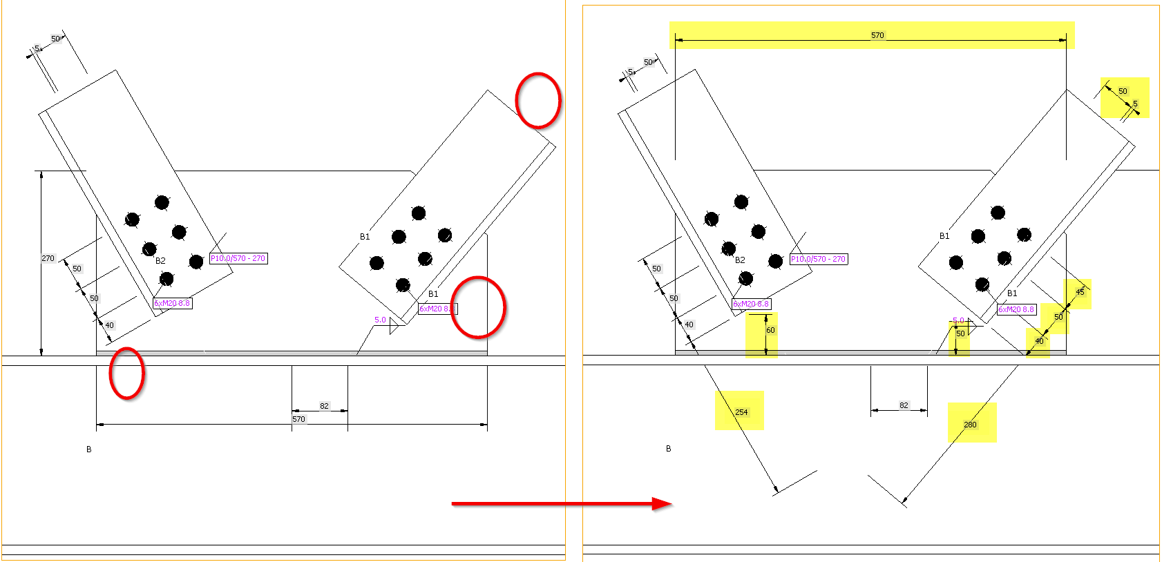
The sketches' readability is critical for avoiding mistakes in the final design in 3D CAD software due to the needs to avoid overlapping texts with the lines, etc. By providing clearer sketches where the annotation marks do not overlap with other objects anymore, the sketches are simple, clear, and fully readable.
No overlapping of texts and lines
The special allocation algorithm eliminates the aforementioned overlapping of annotation marks in sketches, preventing the occurrence of cluttered sketches.
To enhance sketch readability and annotation distribution, we use a quadrant principle: By centering the picture and dividing sketches into four quadrants around the node base point, annotations are strategically placed in the best positions within the corresponding quadrant. Using this principle, we reach a much better and more logical distribution of the annotation marks of plates, welds, and bolts.
Big display in the report
Sketches occupy approximately two-thirds of an A4 page, ensuring readability and utility in the final report. This prevents sketches from being too small and surrounded by excessive empty spaces, detracting from the overall quality and effectiveness of the documentation.
Sketches are set to ON in the report by default.
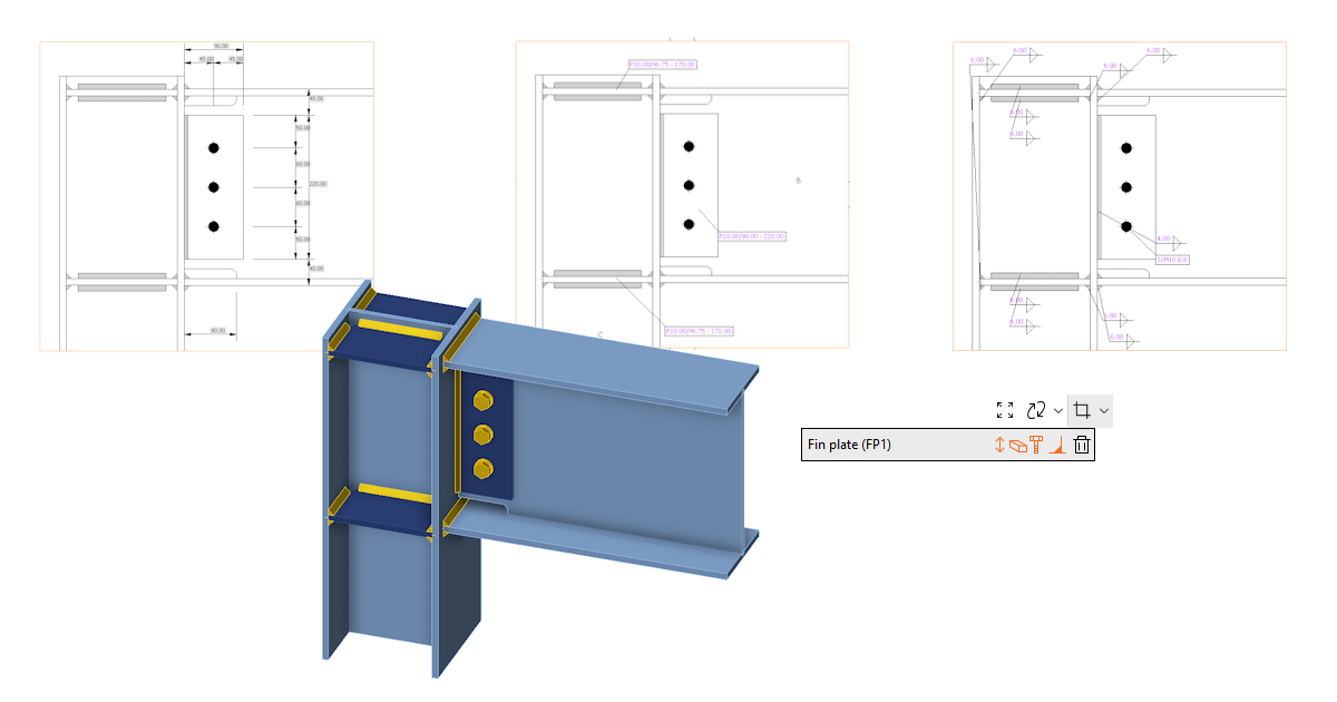
Improved annotations of operations
Annotations in key manufacturing operations such as fin plate, widener, stiffener, and gusset plate, help streamline the design process and eliminate sketch overlaps. Repositioning annotations, adding missing dimensions, and correcting inaccuracies avoid the risk of unclear sketches and incomplete details.
Section Editor and settings
The Section Editor accelerates the management and customization of user-defined sections within the Design tab, directly affecting ease of use. These settings are reflected in the Report and preserved with the model, ensuring consistency across documentation. You have the flexibility to easily remove sections or tailor the visibility of various annotations to suit the complexity of the section, resulting in clarity and user control over section presentations.
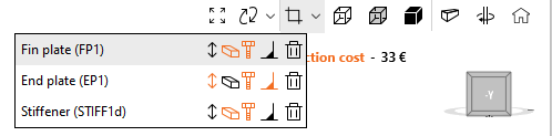
It is available in the Design tab, directly under the original button for opening the section mode view.
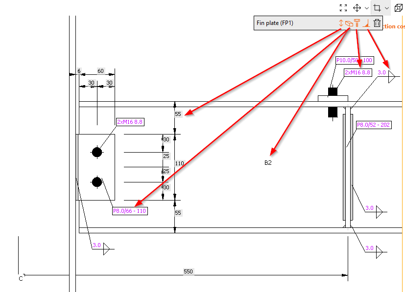
Functions available in the section editor are:
- Show/hide annotations
- Show/hide member and plate labels
- Show/hide bolt descriptions
- Show/hide weld symbols
- Delete sketch
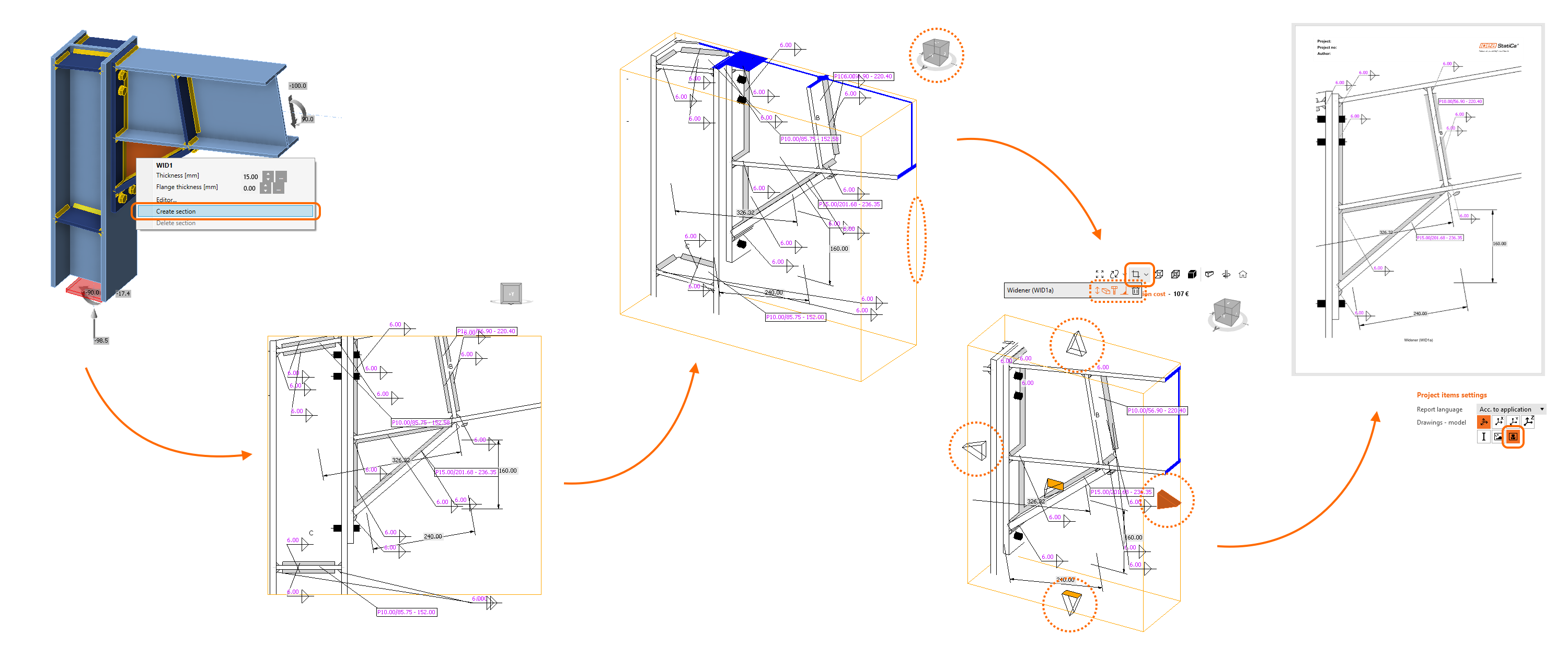
How to work with sketches
- To create a new sketch/section view, use the right mouse button in the 3D scene and select Create section.
- Rotate the model to view the orange box defining the section.
- Click its boundaries and adjust them using the arrows around the box.
- In the menu above the 3D scene, you can select which entities will be included in the section view.
- The sketch will be automatically printed in the report unless you change the settings.
You can edit the section anytime using the Section editor button in the menu above the 3D scene. Also, you can create as many sections as you wish.
Find out more in the How to create a section view article.
Released in IDEA StatiCa version 24.0.