Betonblokk szerkezeti modellje
Méretezési modell
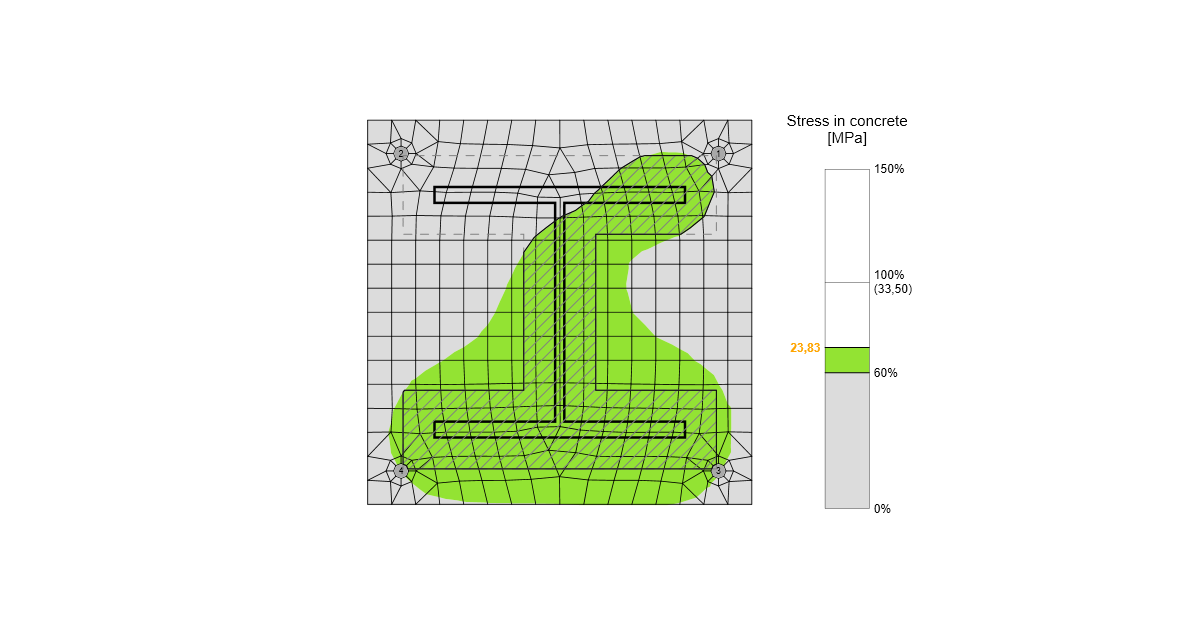
A CBFEM-ben célszerű a betonblokkot 2D kontaktelemekkel egyszerűsíteni. A beton és a talplemez közötti kapcsolat csak nyomást vesz fel. A nyomás a Winkler-Pasternak altalajmodellen keresztül adódik át, amely a betonblokk alakváltozásait reprezentálja. A talplemez és a betonblokk közötti húzóerőt a horgonycsavarok veszik fel. A nyíróerőt a talplemez és a betonblokk közötti súrlódás, a nyírófog, valamint a horgonycsavarok hajlítása és súrlódás útján adódik át. A csavarok nyírási ellenállását analitikusan értékelik. A súrlódást és a nyírófogat teljes egypont-kényszerfeltételként modellezik a talplemez–beton érintkezési síkjában.
Alakváltozási merevség
A betonblokk merevsége az oszlopalap méretezéséhez rugalmas félgömb formájában becsülhető. A Winkler-Pasternak altalajmodellt általánosan alkalmazzák az alapozás egyszerűsített számításához. Az altalaj merevsége a beton rugalmassági modulusa és az altalaj hatékony magassága alapján határozható meg:
\[ k = \frac{E_c}{(\alpha_1 + \upsilon) \sqrt{\frac{A_{eff}}{A_{ref}}}} \left( \frac{1}{\frac{h}{a_2 d} + a_3}+a_4 \right) \]
ahol:
- k – a betonaltalaj nyomási merevsége
- Ec – a beton rugalmassági modulusa
- υ – a betonblokk Poisson-együtthatója
- Aeff – hatékony nyomott terület
- Aref = 1 m2 – referenciaterület
- d – talplemez szélessége
- h – betonblokk magassága
- a1 = 1,65; a2 = 0,5; a3 = 0,3; a4 = 1,0 – együtthatók
A képletben SI mértékegységeket kell használni, az eredmény mértékegysége N/m3.
Nyíróterhelés átadása a talplemezen
A talplemezen a nyíróterhelés háromféle módon adható át:
- Súrlódás
- Nyírófog
- Horgonyok
A felhasználók a talplemez-művelet szerkesztésével választhatják ki az átadási módot. A szoftverben az átadási módok kombinációja nem megengedett, azonban az EN 1993-1-8 – 6.2.2. pont és az Fib 58 – 4.2. fejezet bizonyos feltételek mellett lehetővé teszi a horgonyok és a súrlódás általi nyíróerő-átadás kombinációját. Általánosságban elmondható, hogy a súrlódás elhanyagolása konzervatív megközelítés a lehorgonyzás méretezésénél, bár egyes esetekben a használhatósági határállapoton a beton repedezettségének alábecsléshez vezethet. Főszabályként a súrlódási ellenállást el kell hanyagolni, ha:
- a habarcsréteg vastagsága meghaladja a horgonyátmérő felét,
- a lehorgonyzási kapacitást szélközeli feltétel szabályozza,
- a lehorgonyzás földrengési terhek felvételére szolgál.
A nyírófogával való kombinációt az alakváltozási kompatibilitás miatt soha nem szabad megengedni.
Nyíróterhelés átadása súrlódással
A nyírási ellenállás egyenlő az ellenállási biztonsági tényező és a Szabványbeállításokban szerkeszthető súrlódási együttható, valamint a nyomóterhelés szorzatával. A nyomóterhelés minden erőt magában foglal, pl. ha az oszlopalap nyomóerővel és hajlítónyomatékkal terhelt, a súrlódási nyírási ellenálláshoz használt nyomóterhelés nagyobb lehet az alkalmazott nyomóerőnél.
Nyíróterhelés átadása nyírófog segítségével
A nyírófogat a talplemez alatt betonba ágyazott csonkként szimulálják. A nyíróterhelés átadása egyenletes tehereloszlással történik, amely a betonblokkba ágyazott nyírófog teljes részére hat, azaz a nyírófog betonfelszín alatti összes csomópontja egyenletesen terhelt. A betonfelszín felett habarcsban lévő nyírófog-rész nem vesz részt a nyíróterhelés átadásában.
Figyelembe kell venni, hogy az alkalmazott nyíróterhelés (a talplemezen) és a nyírási ellenállás (a betonba ágyazott nyírófog félmagassága) közötti karhossz hajlítónyomatékot okoz, amelyet a betonban lévő nyomóerőnek és a horgonyokban lévő húzóerőknek kell felvenni.
A nyírófog héj végeselem-módszer elemekből áll, és szabályos lemezként ellenőrzik. A nyírófog talplemezhez való hegesztéseit szintén szabványos eljárásokkal ellenőrzik az IDEA StatiCa Connection programban. A kézi számítás általában gerendaelméletet feltételez a nyírófognál, bár ez nem pontos, mivel a nyírófog hossz-szélesség aránya nagyon kicsi. Ezért jelentős eltérés lehet az IDEA StatiCa Connection és a kézi számítás között.
Nyíróterhelés átadása horgonyok segítségével
A nyírási ellenállást a horgonyok nyírási ellenállása határozza meg. A horgonyok acél ellenállása elasztoplasztikus terhelés-alakváltozás görbével rendelkezik, a beton tönkremeneteli módokat azonban tökéletesen ridegnek tekintik.