
Comment fusionner des assemblages depuis les logiciels CAO et EF
Cette fonctionnalité est disponible pour tous les logiciels EF/CAO pris en charge. Il est important de noter que le lien entre les deux fichiers de projet est maintenu, ce qui permet des mises à jour et des modifications aisées.
Exigences et limitations
La géométrie des modèles d'assemblage importés depuis les logiciels EF et CAO doit être identique. Le modèle d'analyse globale en EF doit représenter fidèlement le modèle CAO réel, en tenant compte de facteurs tels que les excentricités, la position des éléments, les angles entre les éléments, etc.
Si les topologies d'assemblage que vous souhaitez fusionner diffèrent (par exemple, un nombre différent d'éléments ou des variations dans la rotation des éléments), le logiciel émettra un avertissement et aucune fusion ne sera effectuée. De plus, l'option "Charges en équilibre" (garantissant que les forces non équilibrées = 0) constitue un outil de vérification pour vous.
Pour une fusion réussie, l'algorithme compare les positions des éléments dans les deux projets et associe automatiquement les forces aux éléments corrects. Cela signifie que vous n'avez pas à vous soucier de l'ordre des éléments.
Comment fusionner les assemblages importés depuis les logiciels EF et CAO
Vous devez d'abord importer les données des modèles EF et CAO dans deux projets IDEA StatiCa Checkbot distincts, puis fusionner les données dans l'application IDEA StatiCa Connection.
Étape 1 :
- Ouvrez le modèle EF, effectuez le calcul et importez les nœuds concernés dans Checkbot.
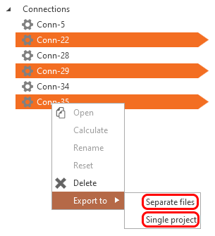
- Sélectionnez le nœud que vous souhaitez dimensionner et exportez-le depuis Checkbot dans un fichier séparé.
Étape 2 :
- Ouvrez le modèle CAO et exportez les nœuds concernés vers Checkbot (un projet Checkbot différent de celui de l'étape 1 précédente - il y en a un pour le modèle EF et un pour le modèle CAO).
- Sélectionnez le nœud que vous souhaitez vérifier normativement et ouvrez-le depuis le projet Checkbot.
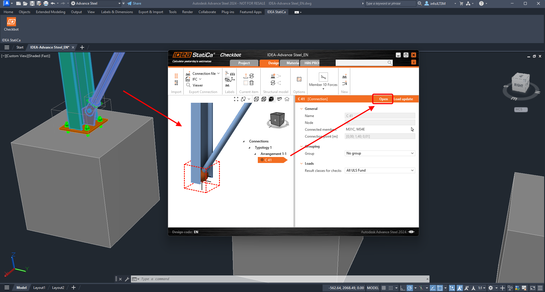
Étape 3 :
- Le modèle d'assemblage est ouvert dans l'application Connection. Cliquez sur le bouton Connection Import et sélectionnez le fichier exporté créé à l'étape 1.
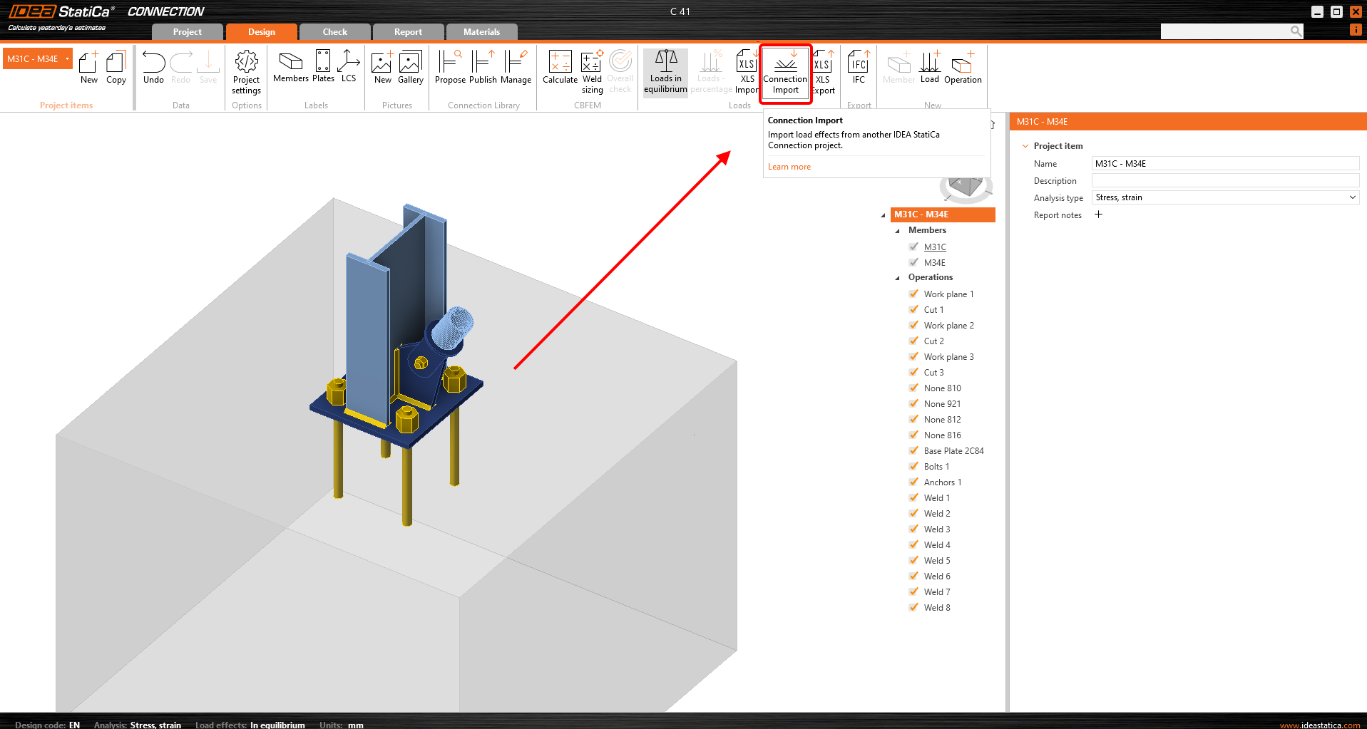
- Vous disposez de l'assemblage dimensionné importé depuis le modèle CAO, et vous avez ajouté en une seule fois les efforts intérieurs de toutes les combinaisons de charges depuis le modèle EF. Cliquez maintenant sur Calculer et examinez les résultats.
Ressources supplémentaires
Vous pouvez suivre le tutoriel pas à pas.