Béton en compression
Type d’assemblage : Pied de poteau
Système d'unité : Métrique
Calcul selon : EN 1993-1-8 et EN 1992-1-1
Investigation : Béton en compression
Acier : S235
Boulons : M20 nuance 4.6
Béton : C20/25
Géométrie
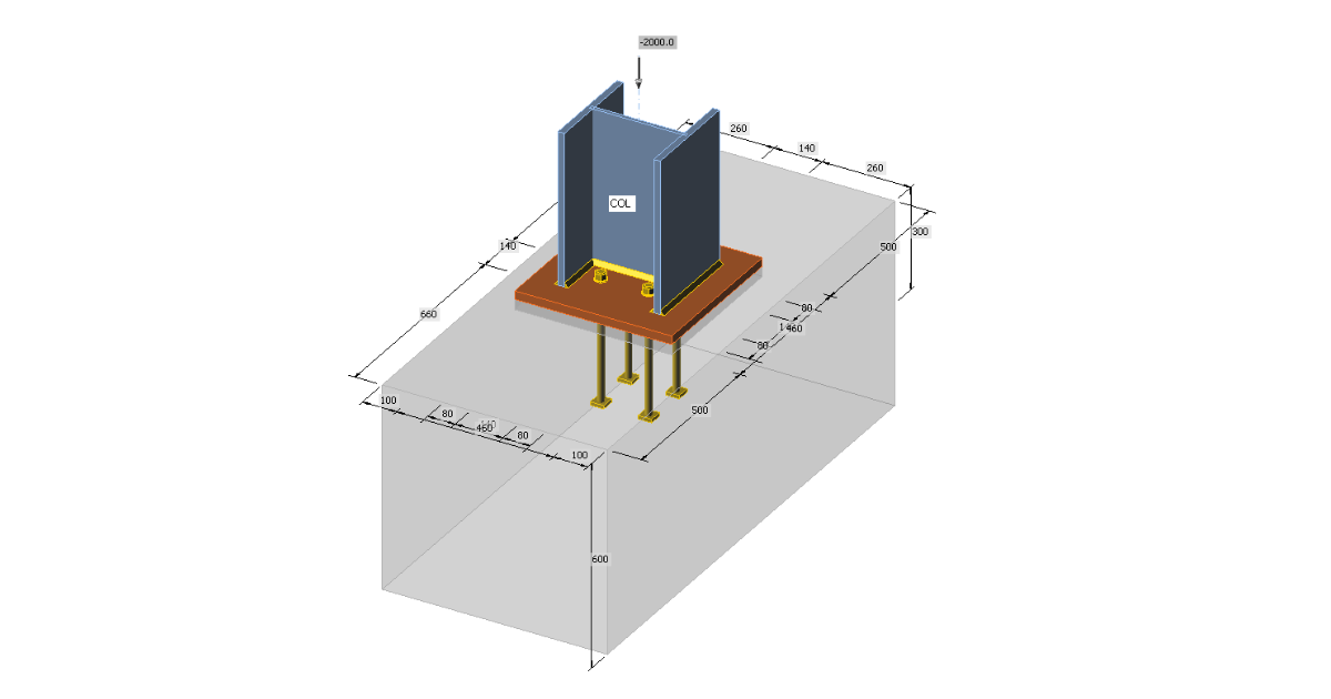
Le pied articulé est calculé pour un poteau HEB 300. La platine d’embase a pour dimensions 460×460 mm. Les boulons d'ancrage sont M20 4.6 placés à l'intérieur des bords du poteau pour réduire la rigidité de l’assemblage. La platine d’embase est scellée sur une plaque de béton de 30mm d’épaisseur.
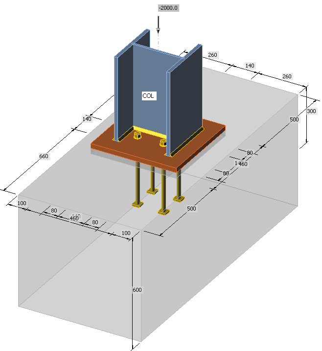
Charge appliquée
Le poteau est chargé par un effort de compression de 2 000 kN.
Calcul manuel
Général
Trois composants sont examinés: âme et aile du poteau comprimé, béton en compression y compris le scellement, soudures. Tous les composants sont calculés conformément à l’EN 1993-1-8 et l’EN 1992-1-1. Dans cet exemple, seul le tronçon en T équivalent comprimé selon l’EN 1993-1-8 – Cl. 6.2.5 est étudié.
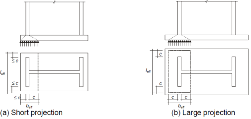
Le comportement élastoplastique de la platine d’embase est prévu dans la norme. La contrainte de compression uniforme sous la zone efficace de la platine d’embase, égale à la résistance à l’écrasement (portance) du béton augmentée par l'état de contrainte triaxiale, f jd, est estimée à la résistance de compression de calcul de l’assemblage. La zone efficace A eff est créée en utilisant une largeur de portance supplémentaire, c. Cette valeur est calculée selon la formule suivante:
\[ c=t\sqrt{\frac{f_y}{3f_{jd} \gamma_{M0}}} \]
où :
- t – épaisseur de la platine d’embase
- fy – limite élastique de la platine d’embase
- fjd – résistance à l’écrasement (portance) du béton
- γM0 = 1.0 – résistance à l’écrasement (portance) du béton
La section du poteau est augmentée de cette largeur d'appui supplémentaire, à moins qu'elle ne dépasse la surface de la platine d’embase. Les efforts membranaires sont négligés pour plus de simplicité, bien qu'ils puissent être assez importants, par exemple dans le cas de poteaux à section fermée (tube).
La résistance à l’écrasement (portance) du béton f jd est déterminée selon l'équation suivante:
\[ f_{jd} = \beta_j \frac{F_{Rdu}}{A_{eff}} \]
où :
- βj – le coefficient du matériau de la fondation, qui peut être considéré comme 2/3 à condition que la résistance caractéristique du scellement ne soit pas inférieure à 0,2 fois la résistance caractéristique de la fondation en béton, et que l’épaisseur du scellement ne soit pas supérieure à 0,2 fois la dimension la plus faible (largeur) de la platine d’embase en acier. Dans le cas où l'épaisseur du scellement est supérieure à 50 mm, la résistance caractéristique de ce scellement doit être au moins la même que celle de la fondation en béton.
- FRdu – l’effort de compression limite donné dans l’EN 1992-1-1 – Cl. 6.7. L’aire chargée A c0 est la zone efficace A eff, et l’aire maximale de diffusion utilisée pour le calcul A c1 doit être géométriquement similaire et concentrique à l’aire chargée. La pente de diffusion est assez raide, hauteur à largeur 2:1.
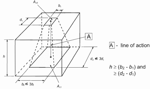
L'augmentation de la résistance du béton, grâce à la contrainte triaxiale dans le béton, peut être exprimée par un coefficient de concentration :
\[ k_j = \sqrt{\frac{A_{c1}}{A_{eff}}} \le 3.0 \]
La résistance à l’écrasement (portance) du béton est alors :
\[ f_{jd} = \beta_j k_j f_{cd} \]
La résistance de compression de calcul de l’assemblage est : Nc,Rd = fjd Aeff.
Cet algorithme est en fait un processus itératif car l’aire efficace dépend de la résistance à l’écrasement (portance) du béton et vice versa. Généralement, la première itération est choisie pour prendre l’aire de la platine d’embase comme aire efficace. Avec la diminution de cette aire efficace, le coefficient de concentration augmente et avec d'autres itérations, la résistance à la compression de calcul de l’assemblage augmente également. En particulier pour les platine d’embase inutilement grandes, l'augmentation peut être importante mais souvent, seule la première itération est suffisante pour que la résistance à la compression de calcul dépasse l’effort de compression de calcul.
Exemple
La section du poteau est représentée sur la figure suivante :
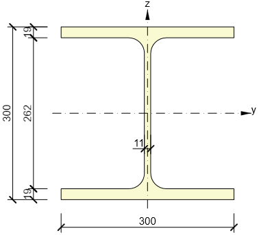
La première étape consiste à calculer la résistance à l’écrasement (portance) du béton avec l'hypothèse que la platine d’embase entière est l’aire chargée, A c0 = 460 2 = 211 600 mm2. L’aire de diffusion de calcul doit être géométriquement similaire et concentrique à la platine d’embase. Le décalage de béton est de 500 mm dans un sens mais seulement de 100 mm dans l'autre. L’aire de diffusion de calcul peut donc être augmentée de 100 mm dans toutes les directions. La hauteur du bloc de béton est suffisante, h = 600 mm ≥ (660 – 460) = 200 mm. L’aire de diffusion de calcul est A c1 = 660 2 = 435 600 mm². Le coefficient de concentration est :
\[ k_j = \sqrt{\frac{A_{c1}}{A_{c0}}} = \sqrt{\frac{435600}{211600}} = 1.435 \]
Finalement, la résistance à l’écrasement (portance) du béton est :
\[ f_{jd} = \beta_j k_j f_{cd} = 0.67 \cdot 1.435 \cdot 13.333 = 12.756 \, \texttt{MPa} \]
Ensuite, la largeur de portance supplémentaire est calculée :
\[ c=t\sqrt{\frac{f_y}{3f_{jd} \gamma_{M0}}} = 25 \sqrt{\frac{235}{3 \cdot 12.756 \cdot 1}} = 62 \, \texttt{mm} \]
Et l’aire efficace peut être construite :
Aeff = 2 · (2 · 62 + 19) · (300 + 2 · 62) + (262 – 2 · 62) · (2 · 62 + 11) = 139 894 mm2.
La résistance à la compression de calcul de l’assemblage est N c,Rd = f jd A eff = 12,756 · 139 894 = 1 784 kN. Une seconde itération est nécessaire.
L’aire efficace est prise égale à l’aire chargée et elle se propage dans un carré avec une taille latérale de 660 mm. Le coefficient de concentration pour la deuxième itération est :
\[ k_j = \sqrt{\frac{A_{c1}}{A_{c0}}} = \sqrt{\frac{435600}{139894}} = 1.765 \]
La résistance à l’écrasement (portance) du béton est :
\[ f_{jd} = \beta_j k_j f_{cd} = 0.67 \cdot 1.765 \cdot 13.333 = 15.685 \, \texttt{MPa} \]
La largeur de portance supplémentaire est :
\[ c=t\sqrt{\frac{f_y}{3f_{jd} \gamma_{M0}}} = 25 \sqrt{\frac{235}{3 \cdot 15.685 \cdot 1}} = 56 \, \texttt{mm} \]
La largeur de portance supplémentaire est :
Aeff = 2 · (2 · 56 + 19) · (300 + 2 · 56) + (262 – 2 · 56) · (2 · 56 + 11) = 126 394 mm2.
La résistance de compression de calcul de l’assemblage est :
Nc,Rd = fjd Aeff = 15.685 · 126 394 = 1 982 kN.
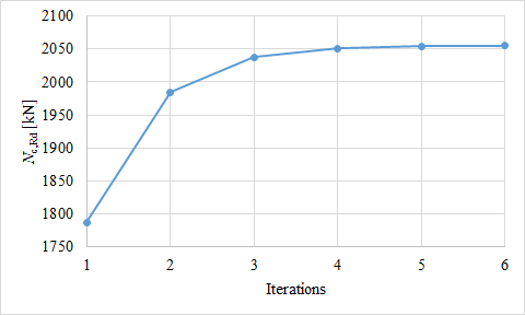
Les itérations suivantes sont représentées sous la forme d'un graphique. On voit que trois itérations sont généralement suffisantes et que la résistance à la compression de calcul n’augmente pas de manière significative par la suite.
Résultats dans IDEA Connection
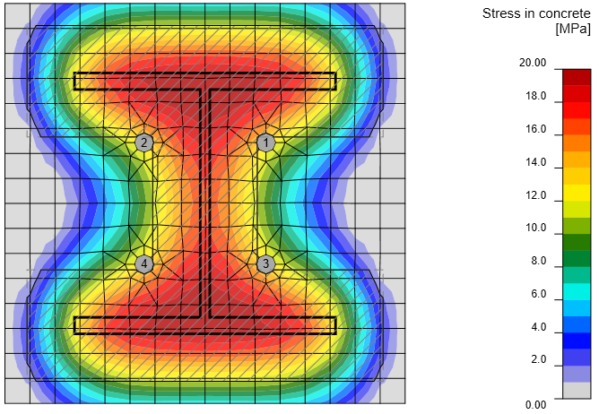
L’aire efficace dans la portance est dans IDEA Connection déterminée en utilisant l'intersection de deux zones pour permettre de vérifier tout chargement et toute forme de poteau, y compris les raidisseurs ou les élargisseurs. Une zone est déterminée par l'analyse éléments finis et montre la zone de la platine d’embase en contact avec le béton. La deuxième zone est calculée par l'algorithme de la méthode des composants en utilisant la largeur de portance supplémentaire c. Le logiciel effectue des itérations jusqu'à ce que la différence entre les itérations de largeur de portance supplémentaire soit inférieure à 1 mm.
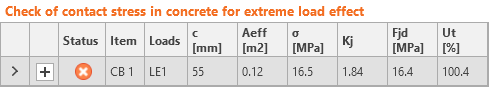
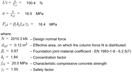
La résistance à la compression de cette platine d’embase selon IDEA Connection est de 1 992 kN.
Comparaison
La résistance du béton en portance dans IDEA Connection (1 992 kN) est ici légèrement inférieure à celle du calcul manuel avec plusieurs itérations (2 055 kN) car l’aire efficace est légèrement plus petite. La différence est seulement de 3 %.