Description
L'objectif de cette étude est la vérification de la méthode des éléments finis basée sur les composants (CBFEM) d'un raidisseur d'âme de poteau de classe 4 dans un assemblage poutre-poteau avec un modèle EF de recherche (RFEM) créé dans le logiciel Dlubal RFEM et la méthode des composants (CM).
Modèle EF de recherche
Le modèle EF de recherche (RFEM) est utilisé pour vérifier le modèle CBFEM. Dans le modèle numérique, des éléments coques quadrilatéraux à 4 nœuds situés aux coins sont utilisés. Une analyse géométriquement et matériellement non linéaire avec imperfections (GMNIA) est appliquée. Les imperfections géométriques équivalentes sont dérivées du premier mode de flambement, et l'amplitude est définie conformément à l'Annexe C de EN 1993-1-5:2006. Le modèle numérique est présenté à la Fig. 6.3.1.

\[ \textsf{\textit{\footnotesize{Fig. 6.3.1 Modèle EF de recherche d'un assemblage poutre-poteau avec raidisseur d'âme de poteau élancé}}}\]
CBFEM
La procédure de calcul pour les plaques élancées est décrite à la section 3.10. L'analyse linéaire de flambement est implémentée dans le logiciel. Le calcul des résistances de calcul est effectué conformément à la procédure de calcul. FCBFEM est interpolé par l'utilisateur jusqu'à ce que ρ ∙ αult,k/γM1 soit égal à 1. Un assemblage poutre-poteau avec un raidisseur d'âme de poteau élancé est étudié. La même section transversale est utilisée pour la poutre et le poteau. L'épaisseur du raidisseur d'âme de poteau varie. La géométrie des exemples est décrite dans le Tab. 6.3.1. L'assemblage est chargé par un moment fléchissant.
Tab. 6.3.1 Aperçu des exemples
| Exemple | Semelle poteau/poutre | Âme poteau/poutre | Raidisseur | Matériau | ||
| bf | tf | hw | tw | ts | ||
| [mm] | [mm] | [mm] | [mm] | [mm] | ||
| t3 | 400 | 20 | 600 | 12 | 3 | S235 |
| t4 | 400 | 20 | 600 | 12 | 4 | S235 |
| t5 | 400 | 20 | 600 | 12 | 5 | S235 |
| t6 | 400 | 20 | 600 | 12 | 6 | S235 |
Comportement global et vérification
Le comportement global d'un assemblage poutre-poteau avec un raidisseur d'âme de poteau élancé d'épaisseur 3 mm, décrit par le diagramme moment-rotation dans le modèle CBFEM, est présenté à la Fig. 6.3.2. L'attention est portée sur les caractéristiques principales : la résistance de calcul et la charge critique. Le diagramme est complété par un point où la plastification commence et la résistance à 5 % de déformation plastique.

\[ \textsf{\textit{\footnotesize{Fig. 6.3.2 Courbe moment-rotation de l'exemple t3}}}\]
Vérification de la résistance
La résistance de calcul calculée par le logiciel CBFEM Idea StatiCa est comparée avec le RFEM. La comparaison porte sur la résistance de calcul et la charge critique. Les résultats sont présentés dans le Tab. 6.3.2. Le diagramme de la Fig. 6.3.3 c) montre l'influence de l'épaisseur du raidisseur d'âme de poteau sur les résistances et les charges critiques dans les exemples examinés.
Tab. 6.3.2 Résistances de calcul et charges critiques du RFEM et du CBFEM

Les résultats montrent un très bon accord en termes de charge critique et de résistance de calcul. Le modèle CBFEM de l'assemblage avec raidisseur d'âme d'épaisseur 3 mm est présenté à la Fig. 6.3.3a. Le premier mode de flambement de l'assemblage est présenté à la Fig. 6.3.3b.
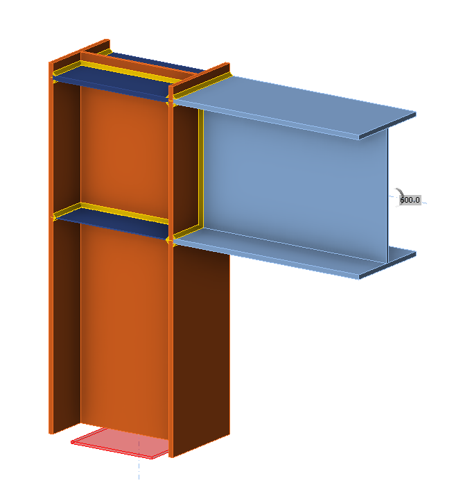
\[ \textsf{\textit{\footnotesize{a)}}}\]
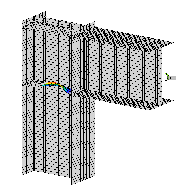
\[ \textsf{\textit{\footnotesize{b)}}}\]

\[ \textsf{\textit{\footnotesize{c)}}}\]
\[ \textsf{\textit{\footnotesize{Fig. 6.3.3 a) Modèle géométrique b) Premier mode de flambement c) Influence de l'épaisseur du raidisseur sur les résistances et les charges critiques}}}\]
Les études de vérification ont confirmé la précision du modèle CBFEM pour la prédiction du comportement du raidisseur d'âme de poteau. Les résultats du CBFEM sont comparés avec ceux du RFEM. Toutes les procédures prédisent un comportement global similaire de l'assemblage. La différence de résistance de calcul est dans tous les cas inférieure à 10 %.
Exemple de référence
Données d'entrée
Poutre
- Acier S235
- Épaisseur de semelle tf = 20 mm
- Largeur de semelle bf = 400 mm
- Épaisseur d'âme tw = 12 mm
- Hauteur d'âme hw = 600 mm
Poteau
- Acier S235
- Épaisseur de semelle tf = 20 mm
- Largeur de semelle bf = 400 mm
- Épaisseur d'âme tw = 12 mm
- Hauteur d'âme hw = 560 mm
- Hauteur de section h = 600 mm
Raidisseur d'âme de poteau supérieur
- Acier S235
- Épaisseur du raidisseur tw = 20 mm
- Largeur du raidisseur hw = 400 mm
Raidisseur d'âme de poteau inférieur
- Acier S235
- Épaisseur du raidisseur tw = 3 mm
- Largeur du raidisseur hw = 400 mm
Paramètres de calcul – Modèle et maillage
- Nombre d'éléments sur l'âme ou la semelle du plus grand élément : 24
Résultats
- Résistance plastique CBFEM = 589 kNm
- Résistance de calcul au flambement CBFEM (kNm) = 309 kNm
- Facteur de charge critique (pour la résistance de calcul au flambement = 309 kNm) αcr = 0,97
- Facteur de charge à 5 % de déformation plastique αult,k = Résistance plastique CBFEM / Résistance de calcul au flambement CBFEM = 589/309 = 1,91