Vérification normative des boulons et boulons précontraints selon les normes russes
Boulons
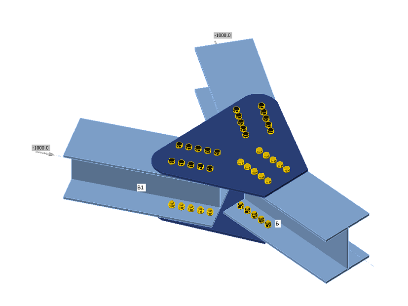
Les boulons sont vérifiés conformément à SP 16, Art. 14.2. L'effort de traction et l'effort de cisaillement dans chaque boulon sont déterminés par analyse par éléments finis. Les efforts de levier sont déterminés par analyse par éléments finis et pris en compte. Chaque plan de cisaillement est vérifié individuellement. La pression diamétrale est vérifiée par rapport à la somme des efforts de cisaillement dans les plans adjacents.
Boulon en cisaillement
Un boulon soumis à un effort de cisaillement de calcul est dimensionné conformément à l'Art. 14.2.9 et doit satisfaire :
\[ N_s \le N_{bs} = R_{bs} A_b \gamma_b \gamma_c \]
où :
- Ns – effort de cisaillement dans un plan d'un boulon
- Nbs – résistance au cisaillement du boulon
- Rbs – résistance de calcul au cisaillement d'un boulon – SP 16, Tableau 5
- Ab – aire de la section brute du boulon
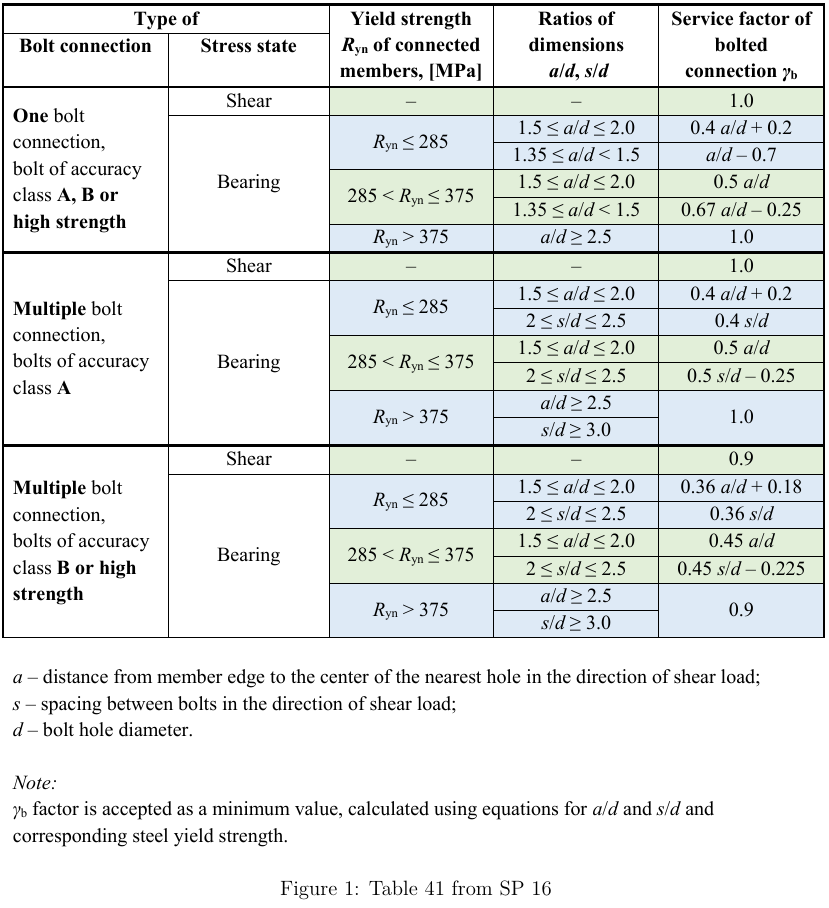
- γb – facteur de service de l'assemblage boulonné – SP 16, Tableau 41 – γb = 1,0 pour boulonnage simple et boulonnage multiple avec classe de précision A, γb = 0,9 pour boulonnage multiple et classe de précision B et boulons haute résistance (Rbun ≥ 800 MPa)
- γc – facteur de service – SP 16, Tableau 1, modifiable dans la configuration normative
| Rbyn [MPa] | Rbs [MPa] |
| \(R_{byn} \le 300 \) | \(0.42 \cdot R_{bun} \) |
| \(300 < R_{byn} \le 400 \) | \(0.41 \cdot R_{bun} \) |
| \(400 < R_{byn} \le 936 \) | \(0.40 \cdot R_{bun} \) |
| \(936 > R_{byn} \) | \(0.35 \cdot R_{bun} \) |
Chaque plan de cisaillement est vérifié individuellement.
Boulon en traction
Un boulon soumis à un effort de traction de calcul est dimensionné conformément à SP 16, Art. 14.2.9 et doit satisfaire :
\[ N_t ≤ N_{bt} = R_{bt} A_{bn} \gamma_c \]
où :
- Nt – effort de traction dans un boulon
- Nbt – résistance à la traction du boulon
- Rbt – résistance de calcul à la traction – SP 16, Tableau 5
- Abn – aire nette de la section transversale du boulon
- γc – facteur de service – SP 16, Tableau 1, modifiable dans la configuration normative
| Rbun [MPa] | Rbt [MPa] |
| \(R_{bun} < 830 \) | \(0.45 \cdot R_{bun} \) |
| \(830 \le R_{bun} < 1040 \) | \(0.54 \cdot R_{bun} \) |
| \(R_{bun} \ge 1040 \) | \(0.70 \cdot R_{bun} \) |
Boulon soumis à une combinaison de cisaillement et de traction
Un boulon soumis simultanément à des efforts de cisaillement et de traction est dimensionné conformément à SP 16, Art. 14.2.13 et doit satisfaire :
\[ \sqrt{\left ( \frac{N_t}{N_{bt}} \right ) ^2 + \left ( \frac{N_s}{N_{bs}} \right ) ^2} \le 1.0 \]
où :
- Nt – effort de traction dans un boulon
- Nbt – résistance à la traction du boulon
- Ns – effort de cisaillement dans un plan d'un boulon
- Nbs – résistance au cisaillement du boulon
Pression diamétrale des boulons
Une plaque soumise à une force de pression diamétrale due à un boulon en cisaillement est dimensionnée conformément à SP 16, Art. 14.2.9 et doit satisfaire :
\[ N_s ≤ N_{bp} = R_{bp} d_b t \gamma_b \gamma_c \]
où :
- Ns – effort de cisaillement dans un boulon agissant sur une plaque
- Nbp – résistance à la pression diamétrale d'une plaque
- Rbp – résistance de calcul à la pression diamétrale ; Rbp = 1,6 · Ru pour la classe de précision A et Rbp = 1,35 · Ru pour la classe de précision B – SP 16, Tableau 5
- Run – résistance ultime de l'élément assemblé
- db – diamètre du boulon
- t – épaisseur de la plaque
- γb – facteur de service de l'assemblage boulonné – SP 16, Tableau 41
- γc – facteur de service – SP 16, Tableau 1, modifiable dans la configuration normative
Chaque plaque est vérifiée individuellement et le cas le plus défavorable est affiché. SP 16 ne précise pas le facteur de service de l'assemblage boulonné, γb, pour les cas hors des limites de détaillage. Par conséquent, la vérification de la pression diamétrale n'est pas effectuée pour ces cas.
Assemblages par friction
Pour les assemblages par friction, le glissement doit être limité et vérifié conformément à SP 16, Art. 14.3. Ces boulons doivent également être vérifiés en tant qu'assemblages par pression diamétrale pour l'état limite ultime après glissement. Un boulon soumis à un effort de cisaillement doit satisfaire :
\[ N_s \le N_{bf} = Q_{bh} \gamma_b \gamma_c \]
où :
- Ns – effort de cisaillement agissant sur un boulon précontraint et un plan de friction
- Nbf – résistance au glissement par friction d'un boulon précontraint et d'un plan de friction
- Qbh = Rbh Abn μ / γh – résistance de calcul au glissement d'un boulon précontraint et d'un plan de friction
- Rbh = 0,7 · Rbun – précontrainte de calcul dans le boulon précontraint – SP 16, Art. 6.7
- Rbun – résistance ultime à la traction du boulon
- Abn – aire de la section résistante à la traction
- μ – coefficient de frottement pour les boulons précontraints – SP 16, Tableau 42, modifiable dans la configuration normative
- γh – coefficient en cas de serrage des boulons – SP 16, Tableau 42
- Trous normaux : chargement statique, Δ ≤ 4 mm ; chargement dynamique, Δ ≤ 1 mm :
- γh = 1,12 pour μ ≥ 0,42
- γh = 1,17 pour 0,35 ≤ μ < 0,42
- γh = 1,30 pour μ < 0,35
- Trous surdimensionnés : chargement statique, Δ > 4 mm ; chargement dynamique, Δ > 1 mm :
- γh = 1,70 pour μ < 0,35
- γh = 1,35 pour μ ≥ 0,35
- Trous normaux : chargement statique, Δ ≤ 4 mm ; chargement dynamique, Δ ≤ 1 mm :
- Δ – différence entre les diamètres du trou de boulon et du boulon
- γb – facteur de service de l'assemblage par friction – SP 16, Art. 14.3.4
- γc – facteur de service – SP 16, Tableau 1, modifiable dans la configuration normative
Le chargement statique ou dynamique peut être défini dans la configuration normative.
| Nombre de boulons n | \( \gamma_b \) |
| \( n < 5 \) | 0,8 |
| \( 5 \le n < 10 \) | 0,9 |
| \( n \ge 10 \) | 1,0 |
Le nombre d'interfaces effectives, κ, est toujours égal à 1, car chaque interface est vérifiée séparément.
Conformément à SP 16, Art. 14.3.6, pour les boulons dans les assemblages par friction soumis à une combinaison de cisaillement et de traction, le facteur de service de l'assemblage par friction, γb, est multiplié par :
\[ \gamma_b = \gamma_b \cdot \left ( 1 - \frac{N_t}{P_b} \right ) \]
où :
- Nt – effort de traction dans un boulon
- Pb = Rbh Abn – précontrainte dans un boulon
- Rbh = 0,7 · Rbun – précontrainte de calcul dans le boulon précontraint – SP 16, Art. 6.7
- Abn – aire de la section résistante à la traction
Les assemblages par friction doivent également être vérifiés pour l'état limite ultime. Le type de boulon doit être modifié en pression diamétrale – interaction traction/cisaillement, les charges augmentées en conséquence et l'assemblage doit être vérifié à nouveau.