Principes clés de
IDEA StatiCa Connection
Introduction
IDEA StatiCa Connection est un logiciel de calcul basé sur la Méthode des Éléments Finis par Composants (CBFEM), destiné à être utilisé par des ingénieurs structure qualifiés, familiarisés avec la conception des assemblages acier. Il repose sur la compréhension des principes d'ingénierie par les utilisateurs afin de simuler correctement chaque assemblage et d'interpréter le comportement résultant à l'issue de l'analyse par éléments finis. À ce titre, il n'est pas destiné à remplacer les connaissances en ingénierie de l'utilisateur, mais à renforcer ses capacités de conception en s'appuyant sur le moteur CBFEM sous-jacent.
Ce guide résume certains éléments clés du logiciel et il est conseillé à tous les utilisateurs d'IDEA StatiCa de le lire. Ce faisant, l'utilisateur évitera les erreurs courantes susceptibles de conduire à des résultats erronés. De plus, les ressources en ligne du Centre d'assistance sont constamment mises à jour avec de nouvelles informations sur l'utilisation et les principes du logiciel. Enfin, nous vous conseillons vivement de lire le Contexte théorique ainsi que ses annexes nationales.
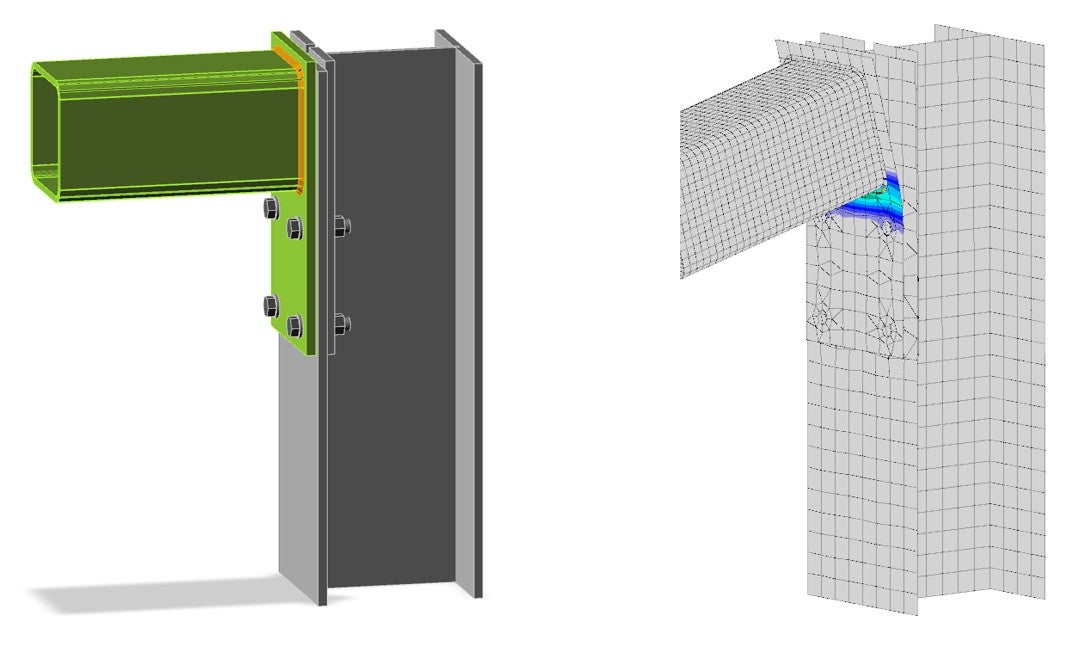
IDEA StatiCa a été développé pour modéliser et concevoir des assemblages acier. À cet égard, l'assemblage doit comporter un seul nœud identifiable où tous les éléments convergent, quelle que soit la complexité de cet assemblage. Veuillez noter que les petites excentricités de certains éléments par rapport au nœud sont prises en compte par le modèle par Méthode des Éléments Finis et ne posent aucun problème au concept de nœud fictif.
En revanche, si plusieurs nœuds peuvent être identifiés dans le modèle, celui-ci peut probablement être classifié comme une structure et l'approche suivie par IDEA StatiCa pourrait être inappropriée et conduire à des résultats erronés.
L'ingénieur doit faire appel à son jugement d'ingénieur pour déterminer si un assemblage peut être considéré comme un ou plusieurs nœuds et utiliser l'approche appropriée.
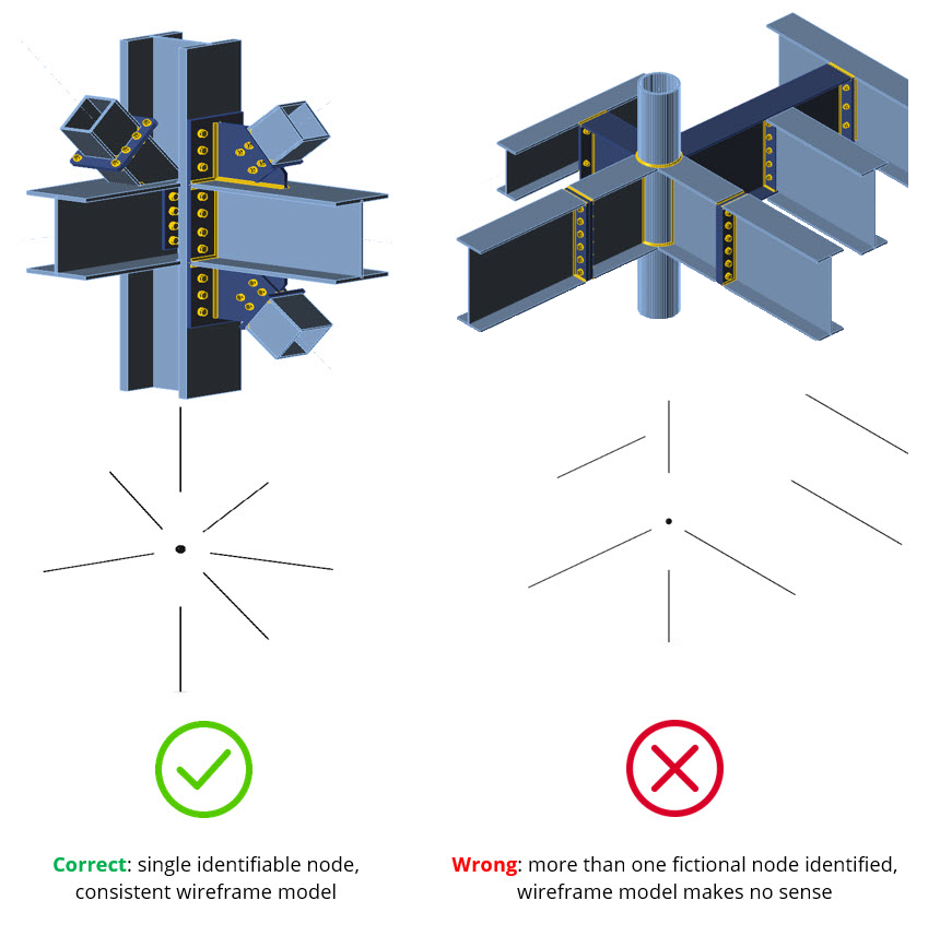
En règle générale, le nœud dans IDEA StatiCa ne doit inclure que les éléments présents dans le logiciel d'analyse globale, car les forces issues de l'analyse ne comprennent que les forces pour ces éléments. Bien entendu, cela est soumis au jugement de l'ingénieur et peut varier d'un cas à l'autre.
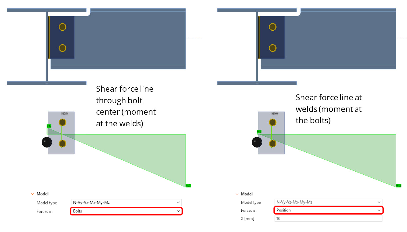
Les effets de charge sont définis au nœud fictif par défaut. L'utilisateur est libre de modifier l'emplacement de la définition du chargement élément par élément. Cela est requis dans certains cas, soit par la norme (par exemple, la conception de platines d'âme selon l'AISC ou le SCI), soit par le cahier des charges.
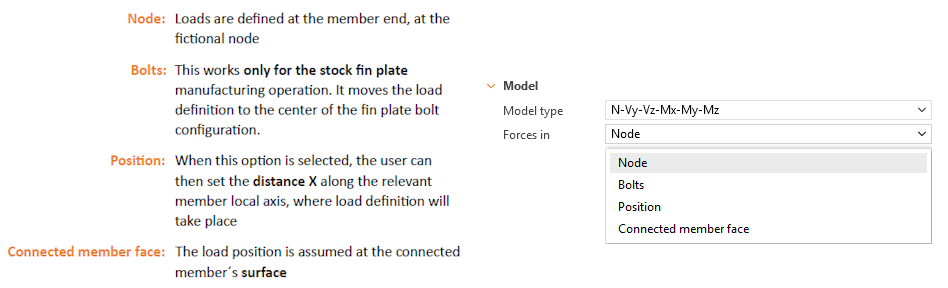
Avant d'utiliser cette fonctionnalité, l'utilisateur doit être conscient que différentes positions de chargement produisent des résultats différents.
Il est courant pour les bureaux d'études de distribuer les charges pour la conception des assemblages sous forme de tableaux de chargement issus des résultats d'enveloppe, ce qui signifie que les composantes de contrainte ne sont pas coexistantes.
Ces charges créent un champ de contraintes irréaliste. Dans notre solution, cet état de contrainte irréaliste se reflète sur le modèle et peut potentiellement conduire à des ruptures.
Veuillez noter que ceci n'est pas une particularité d'IDEA StatiCa, car de tels états de contrainte produiraient des ruptures dans le modèle de calcul global d'origine si ces composantes de contrainte maximales étaient appliquées simultanément. Ce problème est aggravé par le nombre d'éléments connectés.
Pour éviter cette situation, il est fortement conseillé d'utiliser plus d'une combinaison pour vos calculs, provenant du modèle de calcul global d'origine. Il est connu que les résultats pour chaque combinaison sont en équilibre autour des nœuds.
L' utilisation de nos liens BIM rend la transition du modèle global vers la conception des assemblages simple et sans erreur.
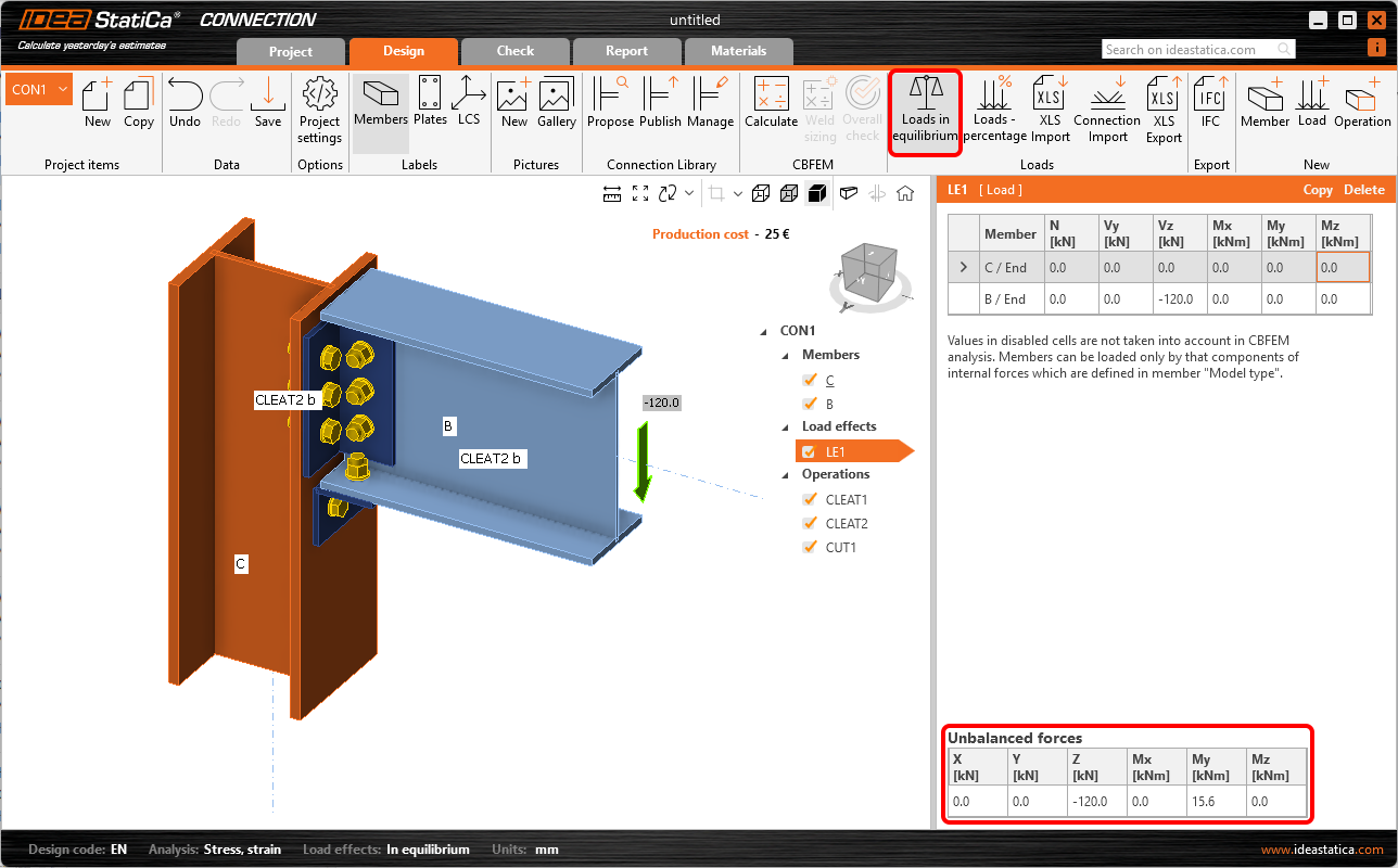
De plus, IDEA StatiCa offre un moyen très simple d'identifier les forces non équilibrées dans votre modèle, en activant le bouton Charges en Équilibre . Ce sont les forces qui seront équilibrées par les réactions des éléments définis comme porteurs.
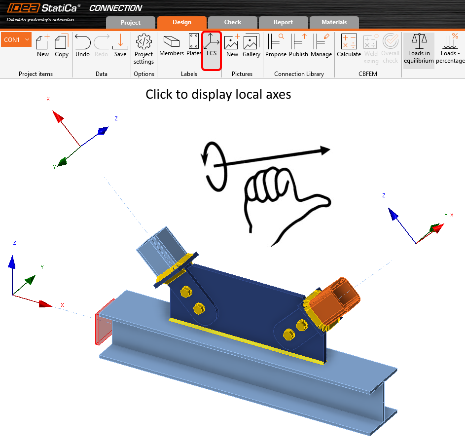
Le signe des moments ne suit pas la convention classique de la statique. Les moments suivent la règle de la main droite autour de l'axe local de l'élément.
Pour afficher l'axe local d'un élément, vous devez activer le bouton LCS dans le panneau de ruban Étiquettes.
Pour définir un moment positif autour d'un axe, l'utilisateur doit pointer son pouce droit vers le côté positif de cet axe. Le recourbement des doigts représente alors une rotation qui correspond au moment positif autour de cet axe.
Veuillez noter que les liens BIM prennent en charge automatiquement les transformations nécessaires lors du transfert des charges depuis le logiciel d'analyse.
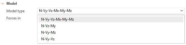
IDEA StatiCa permet de définir différentes options de type de modèle pour les éléments, chacune influençant le type de contrainte appliqué à l'extrémité de l'élément (N-Vy-Vz-Mx-My-Mz correspondant à une extrémité libre/non contrainte). En substance, cette option permet de s'assurer que le chargement appliqué correspond au comportement du modèle global.
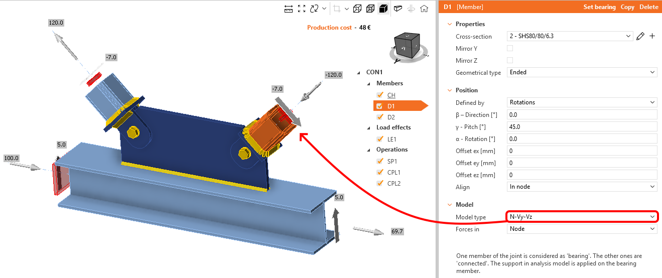
Par exemple, si un élément de contreventement est censé reprendre des efforts axiaux et des efforts tranchants mais aucun moment, l'utilisation d'un modèle non contraint ne serait pas appropriée, car l'élément de contreventement développerait un moment sur sa longueur. Cela peut être évité en utilisant un modèle N-Vy-Vz, où les contraintes elles-mêmes résisteront au moment (qui apparaîtra comme une Non-conformité sous l'onglet Vérification -> Analyse). Ces contraintes peuvent également être utilisées pour assurer la stabilité d'un modèle donné en supprimant certains degrés de liberté. Un exemple clé est un assemblage de contreventement à boulon unique, où le contreventement serait libre de tourner autour de l'axe du boulon. Dans ce cas, l'utilisation d'un type de modèle approprié empêche le développement d'un mécanisme.
En général, si la valeur des efforts/moments repris dépasse significativement le chargement appliqué (selon le jugement du concepteur), cela peut indiquer que le type de modèle choisi n'est pas approprié pour l'assemblage et pourrait conduire à une conception non conservative. Dans ces cas, il est préférable de sélectionner un type de modèle alternatif correspondant aux conditions de chargement/appui attendues, ou d'utiliser le modèle non contraint N-Vy-Vz-Mx-My-Mz.
Le choix du type de modèle est généralement soumis au jugement du concepteur, car les contraintes requises dépendront le plus souvent des spécifications du projet et des conditions de chargement à simuler dans le modèle.
Exemple d'un assemblage de contreventement à boulon unique où le type de modèle doit être N-Vy-Vz, afin d'éviter un mécanisme
Bien qu'il soit possible que pour les assemblages trapus l'analyse de flambement ne soit pas critique, elle est considérée comme une partie intégrante de la méthode CBFEM. À ce titre, il est fortement recommandé d'effectuer une analyse de flambement après l'analyse standard Contrainte/Déformation, afin de s'assurer que ses limites (voir notre Contexte Théorique) sont respectées, et de prouver que la résistance prédite par l'analyse contrainte-déformation peut être pleinement développée.
De plus, le flambement des composants d'assemblage peut influencer la stabilité de l'ensemble de la structure. Dans ce cas, on peut dire que le type de mode de flambement est global. Sinon, le mode de flambement est appelé local.
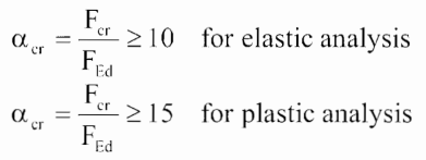
Il est très important de souligner que différentes limites inférieures du facteur critique (αcr, limit) s'appliquent à différents types de modes de flambement. Nous pouvons négliger le flambement global pour les éléments (y compris l'assemblage) dans les cas où le facteur de flambement est supérieur à 15 (en cas de calcul plastique) ou supérieur à 10 (dans le cas où la contrainte sur les plaques est dans le domaine élastique).
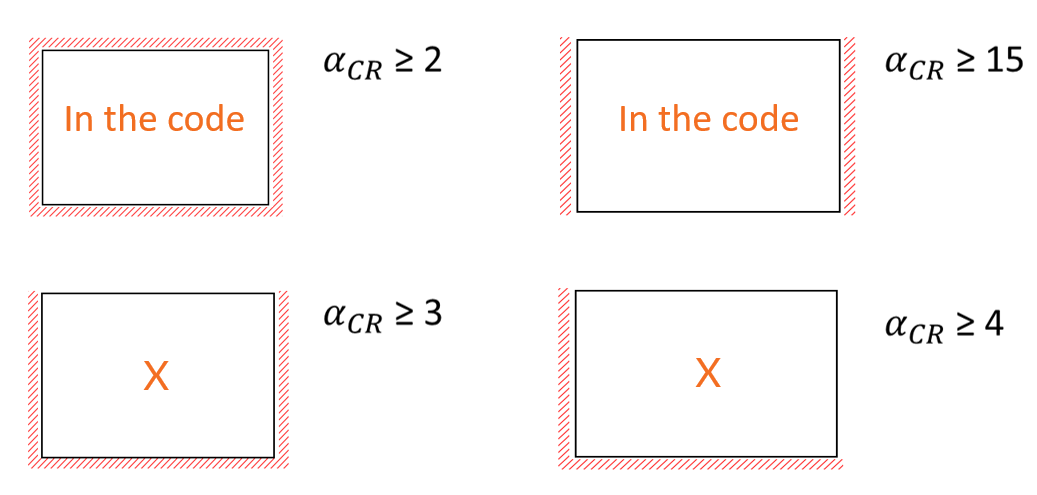
Le flambement local s'applique aux plaques individuelles (raidisseurs, âme de poteau), et les facteurs de flambement limites correspondants sont définis selon les codes de calcul et les expériences de recherche. Les effets du flambement local sont considérés comme négligeables lorsque le facteur de flambement est :
- ≥ 2 - dans le cas d'une plaque supportée sur 4 côtés
- ≥ 3 - dans le cas d'une plaque supportée sur 3 côtés
- ≥ 4 - dans le cas d'une plaque supportée sur 2 côtés (adjacents)
- ≥ 15 - dans le cas d'une plaque supportée sur 2 côtés (opposés)
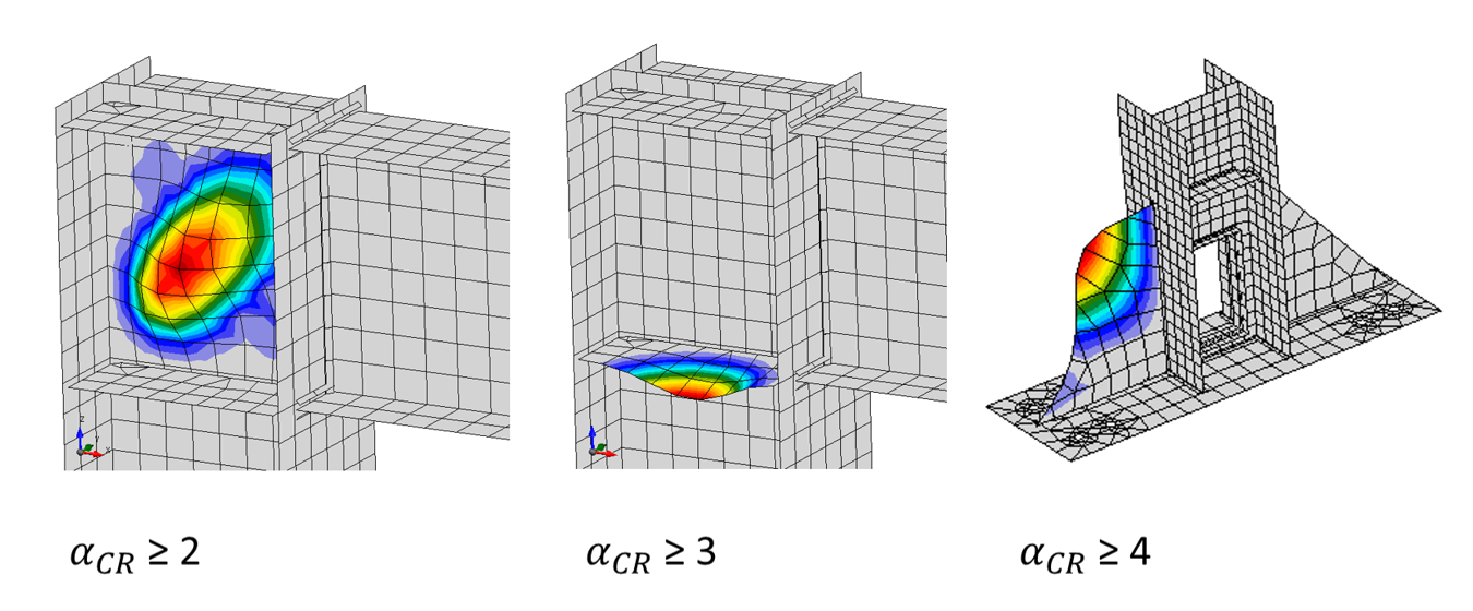
Malheureusement, le type de forme de flambement est soumis au jugement de l'ingénieur et ne peut pas être déterminé par le logiciel. Il appartient à l'utilisateur de décider quel type de flambement s'applique à son modèle en examinant les formes de flambement déformées.
Lorsque nous ajoutons un élément au modèle, sa longueur est calculée automatiquement par le logiciel en fonction de la hauteur de la section transversale. L'algorithme de calcul fait partie de la méthode CBFEM et est calibré d'après des résultats numériques et expérimentaux.
La longueur d'élément calculée garantit qu'une diffusion correcte des contraintes aura lieu conformément à la méthodologie CBFEM.
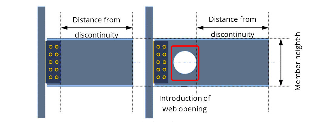
Dans le cas où un élément ou une modification (trous de boulons, encoches, ouvertures, etc.) est ajouté à cet élément, le logiciel ajustera la longueur totale en conséquence afin de maintenir une distance par rapport à la discontinuité.
Cependant, le logiciel permet de modifier le facteur par défaut pour le calcul de la longueur de l'élément, via les paramètres « Code setup », ce qui influence alors la longueur totale. Il est fortement conseillé aux utilisateurs de laisser cette valeur par défaut, car de telles modifications peuvent influencer significativement les résultats. Toutes nos vérifications ont été effectuées avec les paramètres par défaut.
Dans de rares cas, les valeurs par défaut de ce paramètre peuvent conduire à un échec qui ne se produirait pas autrement. Des exemples de scénarios rares peuvent être : 1. des poutres excessivement profondes (par ex. 1,5+ m.) entraînant une distance excessive par rapport à la discontinuité la plus proche, ou 2. un effort tranchant localisé élevé appliqué sur une section de courte longueur (par ex. un court console supportant une poutre de chemin de roulement de pont roulant), qu'IDEA StatiCa modéliserait, par défaut, plus longue que dans la réalité. Les deux cas entraîneraient une flexion importante à l'extrémité chargée.
C'est pour cette raison que ce paramètre est disponible, afin d'offrir aux utilisateurs expérimentés une certaine flexibilité lorsqu'ils traitent ces rares cas où une longueur réduite peut être nécessaire.
Dans de tels cas, où il est absolument clair que le problème est dû à la longueur de l'élément seule, l'utilisateur devra mener une étude pour examiner l'impact de toute réduction du rapport hauteur/longueur de l'élément sur le comportement du modèle (champs de contraintes/déformations et efforts dans les différents composants). Si les résultats correspondent, une réduction du paramètre peut être possible, bien que cela puisse nécessiter d'être effectué conjointement avec les paramètres de maillage dans certains modèles.
En d'autres termes, si l'utilisateur décide de modifier ce paramètre, il doit être en mesure de le justifier de manière adéquate en se référant aux résultats d'une étude associée démontrant que la réduction n'a pas influencé les résultats dans les composants de l'assemblage.
Pour cette raison, nous recommandons de prendre contact avec notre équipe de support avant de modifier l'un de ces paramètres critiques.
Exemple d'étude démontrant une réduction du rapport longueur/hauteur de l'élément sans impact significatif sur le champ de contraintes et le chargement des composants.

Il est important de savoir que différents codes utilisent des conventions différentes pour la définition des soudures. Le code américain, par exemple, utilise les longueurs de côté tandis que l'Eurocode utilise les épaisseurs de gorge pour le calcul. Cette convention est respectée tout au long du projet, y compris dans le rapport de sortie et les dessins.
Il est donc de la responsabilité de l'utilisateur d'ajuster ces dimensions de soudure si nécessaire, afin de les communiquer à des tiers (par exemple, les fabricants) qui utilisent des conventions différentes.

IDEA StatiCa Connection est un outil principalement dédié à la vérification des assemblages d'éléments laminés à chaud, qui ne sont pas significativement affectés par le flambement. Une analyse géométriquement linéaire et matériellement non linéaire est effectuée en raison de son calcul rapide et stable. Cependant, ce type d'analyse ne tient pas compte de la perte de stabilité à chaque étape de calcul, car l'analyse de flambement est linéaire, tandis que la perte de stabilité nécessite une analyse géométriquement non linéaire.
Si vous souhaitez utiliser IDEA StatiCa Connection pour vérifier des assemblages d'éléments à parois minces (formés à froid), assurez-vous d'être un utilisateur expérimenté du logiciel et soyez prêt à appliquer soigneusement votre jugement d'ingénieur sur, au moins, les points suivants :
- Effectuez une analyse linéaire de flambement et évaluez soigneusement chaque mode de flambement. Veuillez garder à l'esprit que les 5 premiers modes de flambement calculés peuvent ne pas être suffisants.
- Ne vous fiez pas à la plasticité des éléments à parois minces et limitez plutôt la contrainte de von Mises à la limite d'élasticité, voire à une valeur inférieure si nécessaire.
- Sachez que le développement du flambement local, qui n'est pas pris en compte à chaque étape de calcul, peut redistribuer différemment les efforts internes dans les composants.
- Sachez que la rigidité des composants peut différer en raison de différents modes de rupture ou de leur combinaison.
- Sachez que les vérifications et les dispositions constructives des composants présentées (par ex. boulons, soudures) suivent les dispositions normatives applicables aux éléments laminés à chaud. Si les dispositions normatives applicables aux éléments à parois minces sont différentes, les vérifications fournies ne leur sont pas applicables.

Dans IDEA StatiCa Connection, l'utilisateur est libre de modéliser des topologies d'assemblage qui étaient impossibles à concevoir auparavant. La gamme d'outils disponibles et les différents types d'analyses (flambement, rigidité, etc.) offrent une compréhension bien plus approfondie du comportement des assemblages conçus qu'auparavant.
Il est de la responsabilité de l'utilisateur d'apprendre, de comprendre et d'appliquer ces outils à ses conceptions, en particulier s'il décide de s'écarter des topologies d'assemblage établies et éprouvées.
Il doit être clair qu'IDEA StatiCa n'est pas en mesure de « corriger » les erreurs de conception conceptuelle. Bien qu'elle puisse aider à les prévenir, avec une application correcte des outils fournis.
Un assemblage conceptuellement erroné avec la rangée supérieure manquante semble passer toutes les vérifications normatives, mais avec l'utilisation de l'outil Forme déformée, une déformation excessive et une concentration de déformations plastiques sont révélées. Cela peut probablement causer des problèmes de serviceabilité, mais sans rupture catastrophique (telle qu'une fracture).