Méthodes et réglementations - Vérifications de la résistance au feu
États limites de résistance au feu
L'état limite de résistance au feu est basé principalement sur le type de construction. Qu'il s'agisse d'un élément porteur ou non porteur, ou qu'il s'agisse d'un mur, d'un poteau ou d'une porte. Les réglementations définissent un certain nombre d'états limites. Les quatre types les plus couramment utilisés sont R, E, I, W.
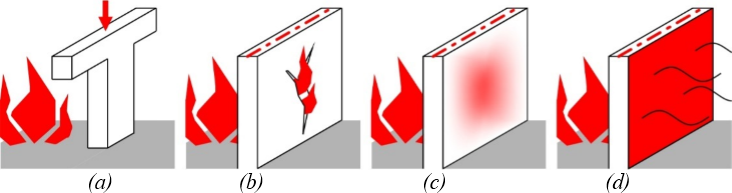
(a) R = Résistance et stabilité, (b) E = Intégrité, (c) I = Fonction d'isolation, (d) W = Murs coupe-feu
État limite „R" (résistance et stabilité)
L'état limite « R » s'applique à toutes les structures porteuses (y compris celles situées à l'intérieur du compartiment feu). En particulier celles qui assurent la stabilité du bâtiment. Celles-ci doivent maintenir leur fonction portante même en cas d'incendie. Pour l'état limite « R », peu importe si la structure est de type poutre ou dalle. L'état limite R doit être satisfait pour les murs, les poteaux, les poutres, les fermes de toiture, les pannes, mais aussi par les raidisseurs, etc.
État limite „E" (intégrité)
L'état limite « E » s'applique à toutes les surfaces des structures de séparation coupe-feu. Lors d'un incendie, aucune fissure ne doit se former dans la structure de compartimentage coupe-feu par laquelle des flammes pourraient passer ou par laquelle des gaz chauds pourraient pénétrer dans un autre compartiment. L'intégrité au feu doit être assurée par les murs coupe-feu et les plafonds séparant les compartiments feu, les autres cloisons coupe-feu ou les soffites (derrière lesquels peuvent se trouver des gaines techniques, etc.), et les fermetures coupe-feu (par exemple les portes), le cas échéant.
État limite „I" (fonction d'isolation)
L'état limite « I » est valable pour les structures de séparation coupe-feu en surface, qui sont destinées à empêcher un échauffement excessif de l'espace du côté opposé au feu. Le matériau sur ou adjacent à la face non exposée à la chaleur ne doit pas s'enflammer. La capacité d'isolation doit être assurée en particulier par des structures planes solidement intégrées telles que les murs coupe-feu et les plafonds entre les compartiments feu. Cela signifie qu'il s'agit principalement d'éléments intérieurs où un incendie peut se produire des deux côtés de la structure et où les personnes situées du côté non exposé sont susceptibles d'être en danger. Les dispositifs d'obturation ouvrant sur une voie d'évacuation protégée doivent également satisfaire à l'état limite « I ».
État limite "W" (limitation du rayonnement thermique)
Les limitations du rayonnement thermique s'appliquent aux structures de séparation coupe-feu en surface ; elles sont similaires à « I », mais avec des exigences moins strictes. L'état limite « W » n'est pas capable d'empêcher l'élévation de température, il limite seulement dans une certaine mesure le flux de chaleur rayonné depuis le côté de la structure opposé au feu. Cependant, ce flux de chaleur rayonné ne doit pas provoquer la propagation de l'incendie ni mettre en danger les personnes s'échappant à proximité d'une telle structure. Il est donc limité à 15 kW/m².
Durée de résistance au feu
La durée de résistance au feu est définie comme la période pendant laquelle la structure doit résister aux effets du feu ou satisfaire à l'état limite requis (ou à plusieurs états limites). La durée de résistance au feu est exprimée en minutes. Les périodes de classification de base sont fixées à 15, 30, 45, 60, 90, 120 et 180 minutes.
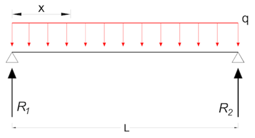
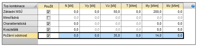
Charge lors d'une résistance au feu
Selon l'Eurocode, on peut considérer de manière simplifiée la charge extrême lors d'un incendie comme 70 % de la combinaison de charges à l'ELU.
Méthodes de résistance au feu
Les méthodes de calcul varient selon l'approche, la précision et la complexité du calcul. Lors de l'analyse d'un élément critique, on peut utiliser la méthode tabulaire, qui est la plus conservative.
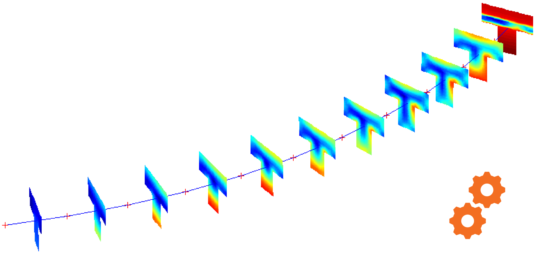
Si la vérification normative n'est pas satisfaisante, il est possible de recourir à des méthodes plus précises telles que la méthode Isotherme 500 ou la dite Méthode des zones. Dans le cas d'une analyse d'une partie de la structure ou même de la structure entière, des simulations numériques telles que la conduction, la convection ou le rayonnement peuvent être utilisées.
Hypothèses de base de la méthode tabulaire
- Toutes les valeurs sont principalement données pour des granulats siliceux (les plus sensibles aux effets du feu)
- Pour les granulats calcaires, la dimension minimale requise de la pierre peut être réduite de 10 %
- L'humidité du béton doit être inférieure à 3 %, sinon il existe un risque d'éclatement explosif
- La température critique du ferraillage en béton est de 500 °C
- La température critique pour le ferraillage de précontrainte est de 400 °C (barres) ou 350 °C (câbles de précontrainte et fils)
- La distance axiale du ferraillage par rapport à la surface doit être inférieure à 70 mm, sinon un ferraillage de surface doit être pris en compte
- Dans le cas de plusieurs couches de ferraillage, la distance axiale moyenne par rapport au bord doit être calculée, la distance axiale minimale de toute couche devant satisfaire au moins au critère R30
- Il est possible d'interpoler linéairement entre les valeurs des tableaux
- Les valeurs données dans les tableaux sont des valeurs minimales et les principes de calcul selon l'Eurocode doivent également être respectés
Poteaux
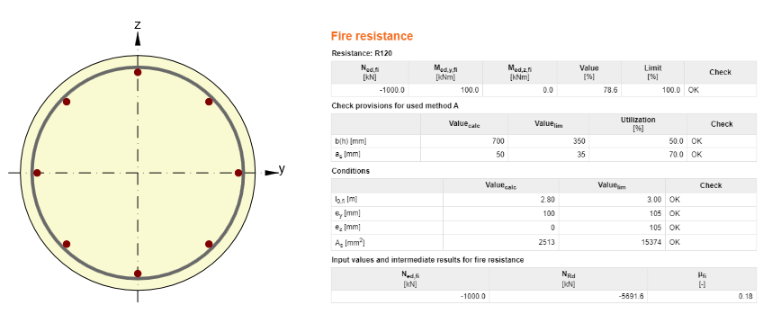
Les poteaux sont généralement vérifiés selon la méthode A ou B. Le choix de la méthode à utiliser dépend uniquement du jugement de l'ingénieur. La vérification normative est valable pour les poteaux principalement soumis à la pression normale et pour les structures contreventées.
Méthode A
- La longueur efficace maximale atteint 3 m.
- La longueur efficace est égale à 0,7*L pour le dernier niveau et à 0,5*L pour chaque niveau supplémentaire.
- Les imperfections initiales sont inférieures à 15 % de la hauteur de la section transversale.
- L'aire maximale du ferraillage est inférieure à 4 % de l'aire de la section transversale en béton.
Méthode B
- La méthode est valable uniquement pour les structures contreventées.
- La longueur efficace du poteau peut être supérieure à 3 mètres.

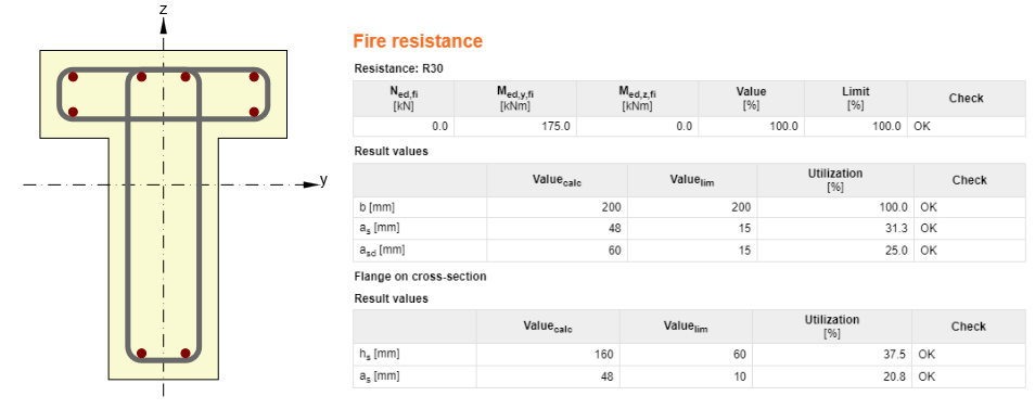
Poutres
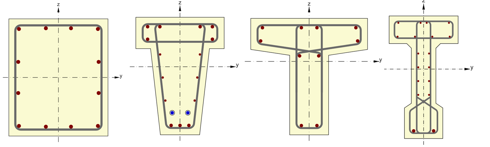
La vérification normative des éléments de type poutre n'est possible que pour des sections transversales rectangulaires, en T ou en I. Dans l'étape suivante, il est nécessaire de distinguer entre les poutres à travée unique ou les poutres continues.
Dalles
Comme pour les éléments de type poutre, il faut choisir entre une dalle simplement appuyée ou une dalle continue. Un autre aspect distingue les appuis créés par des murs ou des poteaux.
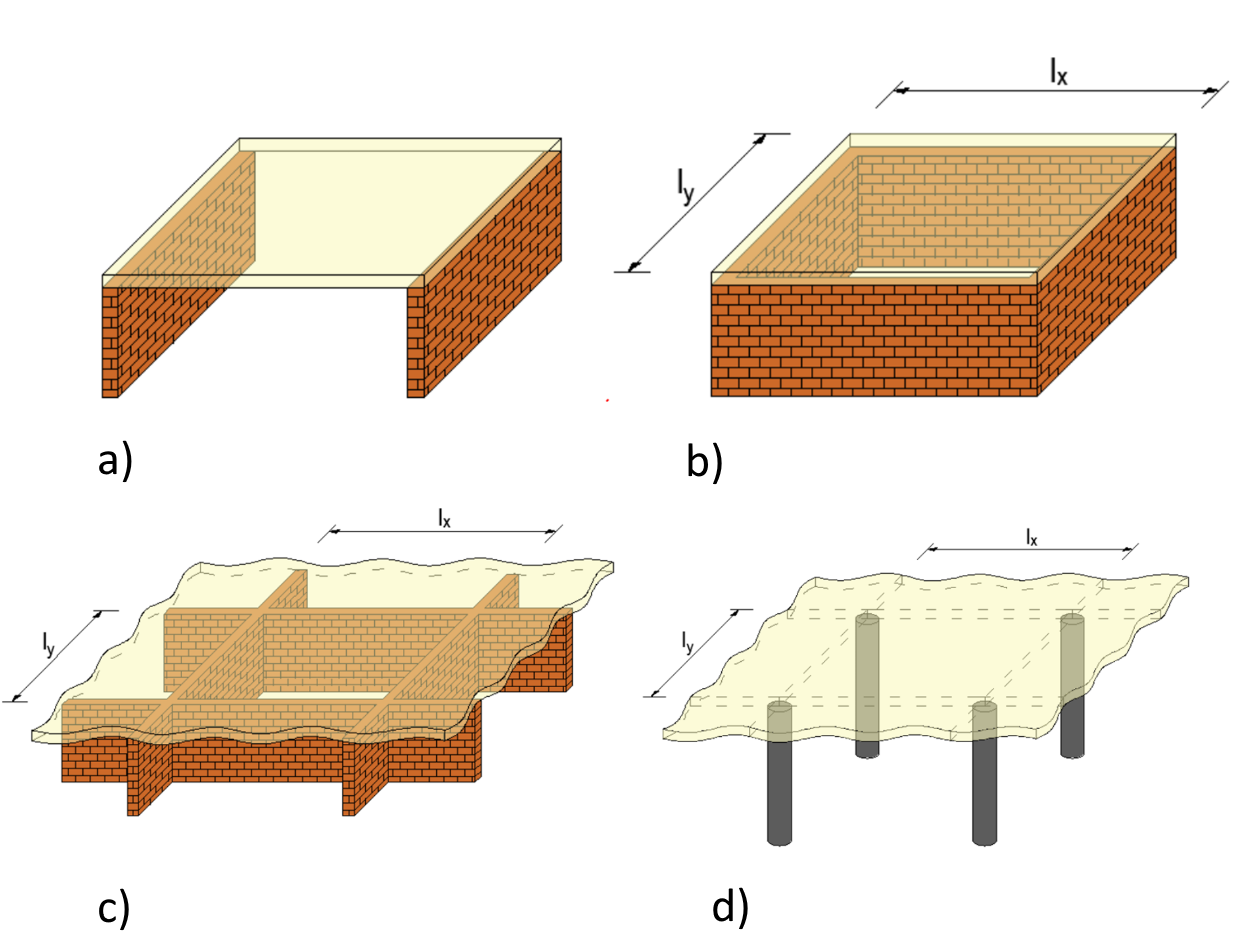
a) Dalle unidirectionnelle, b) Dalle bidirectionnelle, c) Dalle continue - murs, d) Dalle continue - poteaux
Murs
- Le rapport hauteur/épaisseur doit être inférieur à 40
- Résistance au feu EI – intégrité et fonction d'isolation, sans fonction portante
- Résistance au feu REI – intégrité et fonction d'isolation, avec fonction portante
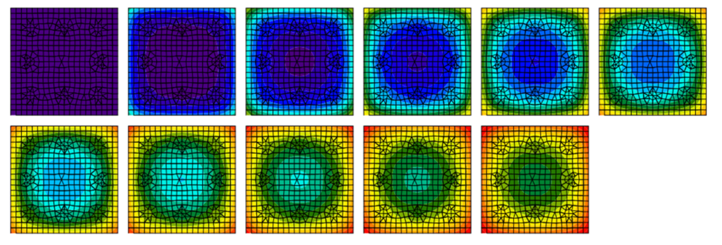
Résumé
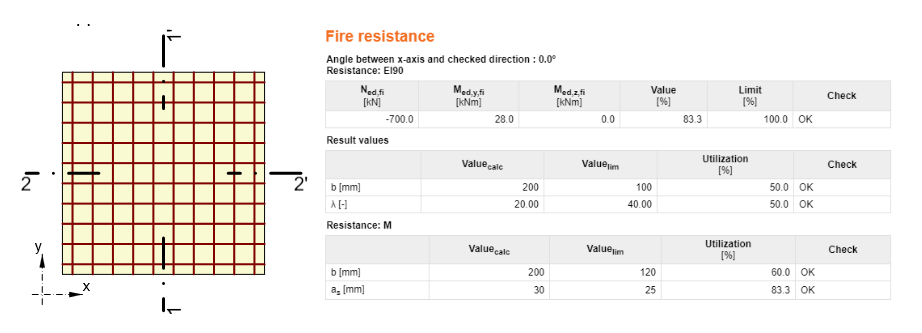
Pour la vérification normative de la résistance au feu des structures, la méthode tabulaire est généralement privilégiée, selon laquelle l'ingénieur obtient très rapidement un résultat satisfaisant ou non. Des méthodes plus avancées telles que la méthode Isotherme 500 ou la Méthode des zones sont également fréquemment utilisées. Les méthodes avancées sont utilisées lorsque des éléments critiques tels qu'un poteau, une poutre, un mur ou une dalle ne satisfont pas à la méthode tabulaire. Les méthodes de simulation numérique telles que la conduction, la convection ou le rayonnement sont principalement appliquées dans le milieu académique. IDEA StatiCa RCS intègre les méthodes tabulaires susmentionnées. Le développement chez IDEA StatiCa fait évoluer l'analyse des méthodes tabulaires vers le niveau des méthodes numériques. Ainsi, vous pouvez vous attendre à une analyse de conduction thermique non stationnaire dans IDEA StatiCa Member dans un avenir proche.