
Mise en scène
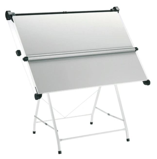
Pour citer une phrase de l'un de mes films préférés : « Il y a bien longtemps, dans une galaxie très lointaine… » un jeune ingénieur tout frais émoulu commençait son parcours. Heureusement, il avait une formation en dessin technique et en dessin d'ingénierie acquise à l'école, ce qui fait que se voir confier une planche à dessin A0 n'était pas si intimidant que ça.
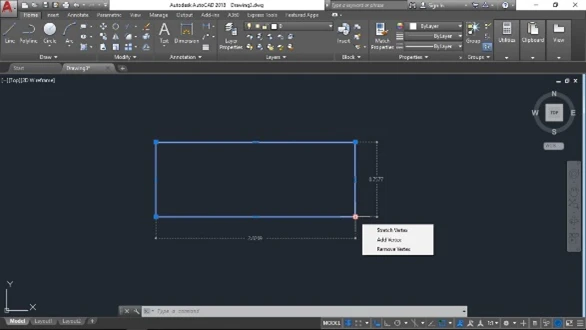
Quelques années plus tard, il vit arriver quelque chose appelé la CAO. Il s'avéra que cela aurait un impact vraiment important sur sa vie — mais il ne le savait pas encore à l'époque. Il s'avéra également que cette technologie aurait tout aussi bien pu s'appeler Dessin Assisté par Ordinateur plutôt que Conception Assistée par Ordinateur, tant c'est ainsi qu'elle était utilisée !
Plusieurs autres années s'écoulèrent, puis une façon totalement nouvelle de faire les choses fit son apparition : le BIM. Là encore, ce n'était pas si intimidant, car les principes du BIM étaient déjà en place puisque (inutile de le préciser) il « modélisait/dessinait » déjà des « objets » une seule fois pour les réutiliser de nombreuses fois. Le BIM était la technologie qui allait révolutionner le secteur du bâtiment — si l'on croyait le battage médiatique !
Comme c'est souvent le cas dans ce secteur, il y eut des hauts et des bas, avec des opportunités à la fois manquées et saisies.
Cette description pourrait s'appliquer à beaucoup d'entre nous et peut-être qu'en lisant ceci, elle vous rappelle un souvenir ou deux. Vous pensez probablement, cependant : « Mais qu'est-ce que c'est qu'une planche à dessin ? ».
J'ai eu le privilège de travailler pour deux des trois grands fournisseurs du monde AEC, ce qui a encore renforcé (excusez le jeu de mots) ma compréhension et mes opinions sur le BIM et les personnes qui l'utilisent.
Voici mon deuxième article sur le BIM — vous pouvez lire le premier ici.
Mon premier article était assez philosophique et posait des questions pertinentes — celui-ci sera davantage axé sur la façon dont nous, chez IDEA StatiCa, tirons parti du flux de travail de collaboration BIM et ce que cela signifie pour les ingénieurs structure.
Je ne vais pas réinventer la roue et passer en revue tous les aspects du BIM car, franchement, cela prendrait beaucoup trop de votre temps et il existe déjà de nombreuses ressources disponibles.
Il suffit de dire que le BIM est un processus ou un flux de travail et, comme tout processus, il comporte des points d'entrée et de sortie. Dans un emploi précédent, j'essayais toujours de montrer une méthode de travail idéale impliquant l'analyse et la modélisation — une méthode qui aboutissait à peu ou pas de duplication. Beaucoup considèrent cette approche comme une solution BIM fermée (en réalité, ce n'en est pas une). Une approche ouverte de l'échange d'informations est à la fois plus sûre et plus efficace.
Ici, chez IDEA StatiCa, nous avons la chance de pouvoir dire que nous sommes agnostiques quant à nos partenaires. Cela nous place dans une position enviable : nous avons une très bonne connaissance de plusieurs applications et de la façon dont elles échangent des données et des informations. Nous savons que certaines applications (pas seulement celles des « trois grands ») ont leurs restrictions et nous savons comment les contourner — je ne pense pas qu'il y en ait beaucoup dans ce secteur qui puissent en dire autant ! Pour voir avec qui nous nous intégrons, consultez cette page.
Quelle est notre approche ?
Nous avons deux approches générales : soit nous développons une intégration en utilisant des API existantes, soit nous fournissons un support pour permettre à des développeurs tiers d'écrire leur propre intégration à l'aide d'un ensemble d'outils que nous mettons à disposition. Dans les deux cas, nous aboutissons à une approche cohérente (à quelques exceptions près).
Il en résulte une application qui s'intègre dans de nombreuses applications tierces ainsi que dans IDEA StatiCa. Elle a été baptisée Checkbot.
Comment fonctionne Checkbot ?
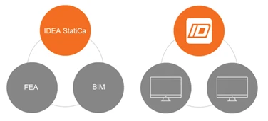
Checkbot fait office de référentiel pour les données exportées depuis plusieurs applications liées aux logiciels BIM et aux logiciels d'analyse par éléments finis (FEA). Il peut contenir à la fois des données géométriques et analytiques. Pour ce faire, il s'intègre dans l'application d'origine sous forme de plug-in, ou en important un fichier généré, soit dans notre propre format IOM, soit en SAF. Le format SAF a été défini et développé par Nemetschek et gagne en popularité auprès de nombreux autres fournisseurs.
Une fois les informations stockées dans Checkbot, elles peuvent être utilisées par Connection ou Member.
Cela signifie qu'en tant qu'ingénieur, vous n'avez pas à ressaisir les informations — ni géométriquement ni analytiquement — ce qui peut représenter un gain de temps considérable, sans parler d'une plus grande précision et d'une réduction des risques.
La façon la plus simple de mettre en évidence ces avantages est de passer par un exemple.
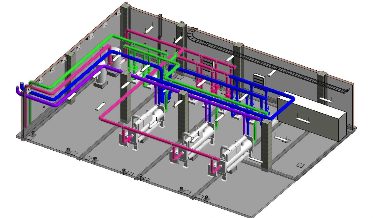
Considérons une structure relativement simple : un portique double travée de type « hit/miss ».
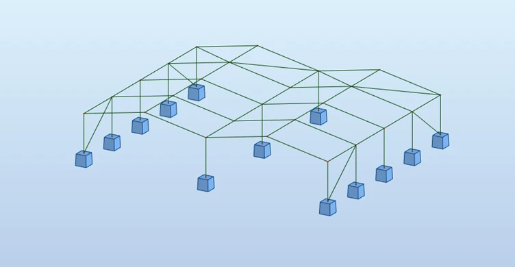
Ces types de structures sont assez courants dans le secteur du bâtiment industriel, mais peuvent impliquer des assemblages complexes, notamment en ce qui concerne les combinaisons.
Certes, la géométrie est assez simple, mais les effets de charge le sont moins. Dans cet exemple, nous pouvons exporter directement depuis le logiciel FEA vers Checkbot.
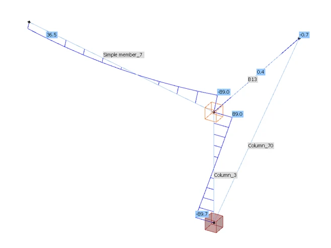
Toutes les combinaisons requises sont exportées, de sorte que nous n'avons pas à parcourir des séries de résultats pour en extraire les valeurs pertinentes — ce qui peut entraîner des erreurs dues à des lectures ou des saisies incorrectes. La géométrie telle que définie dans le logiciel FEA (y compris les propriétés des éléments) a également été exportée. Cela signifie que le concepteur des assemblages peut se concentrer uniquement sur cela : la conception des assemblages. Il a l'assurance que Checkbot collectera les informations telles que définies dans le logiciel FEA. Cependant, cela implique également que les informations initiales doivent être aussi précises que possible. IDEA StatiCa utilise un flux de travail BIM traditionnel : si quelque chose doit changer en ce qui concerne les charges ou la géométrie, cela doit être modifié dans l'application d'origine. Certains peuvent y voir un inconvénient, mais ce flux de travail existe pour une bonne raison : éviter des erreurs coûteuses. Si des modifications sont apportées au modèle FEA, nous pouvons synchroniser les nouvelles informations via Checkbot vers la conception des assemblages — évitant ainsi les erreurs et maintenant la source unique de vérité à jour.
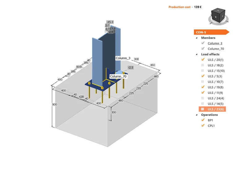
Les mêmes principes peuvent également s'appliquer à l'utilisation d'un modèle piloté par un logiciel BIM. Ici, cependant, nous pouvons utiliser davantage la géométrie sous forme de platines, boulons et soudures — pas seulement les propriétés des éléments. Un inconvénient, toutefois, est que nous n'avons pas de charges et devons donc nous appuyer, éventuellement, sur des techniques traditionnelles telles que les plans…
Ou pas ? La réponse simple est non. IDEA StatiCa peut fusionner ces informations manquantes à partir du modèle FEA, à condition que la géométrie soit identique. Il n'existe aucune autre application capable de faire cela. Ici, chez IDEA, nous pouvons prendre des informations d'un logiciel FEA et les fusionner avec un modèle issu de n'importe quel logiciel BIM pour créer une solution hybride pour la conception des assemblages (les deux applications doivent bien entendu être prises en charge). Les entreprises ne sont pas liées à un seul fournisseur — elles peuvent combiner différentes solutions, ce qui leur offre une plus grande flexibilité. Dans sa forme la plus simple, les résultats peuvent être obtenus à partir d'un tableur Excel.
Cela m'amène à l'une des dernières améliorations apportées à Checkbot : la prise en charge du format SAF. Avec ce format, nous sommes en mesure de proposer un moyen d'importer dans IDEA les informations provenant de toute application FEA prenant en charge le format SAF. Là encore, avec une plus grande précision et plus rapidement.
Conclusions
Utilisé correctement, il ne fait aucun doute qu'un flux de travail ancré dans l'esprit du BIM fournira des résultats plus rapides, plus précis et plus sûrs. Cependant, la mise en garde est que la qualité des informations en sortie dépend de la qualité des informations en entrée, ou pour le dire autrement : des données médiocres en entrée donnent des résultats médiocres en sortie.
De tels flux de travail peuvent être étrangers à de nombreux ingénieurs qui ne sont peut-être pas habitués à partager leurs informations de manière numérique, mais les avantages à le faire sont considérables. On peut en dire autant de ceux qui créent le modèle de fabrication. L'implication précoce des entreprises et des ingénieurs sur tout projet, grand ou petit, sera payante.
J'espère que vous avez apprécié la lecture de mon dernier article de blog. Si vous avez des commentaires, n'hésitez pas à nous contacter — nous serions ravis d'avoir de vos nouvelles !
Commencez votre essai aujourd'hui et profitez de 14 jours d'accès complet et de services gratuits.
Commencer l'essai gratuit