Fuerzas internas y equilibrio en la aplicación Detail
Lo que es importante saber es que las fuerzas internas solo se pueden establecer en el proyecto en casos de modelado de una estructura con extremo recortado, o extremos. Y también que esta función está disponible solo para estructuras particulares, concretamente los elementos de viga. Para más información sobre los elementos individuales, vaya a Tipos de geometría en Detail.
Por lo tanto, debe saber cuándo necesita establecer las fuerzas internas. Ahora, veamos cómo.
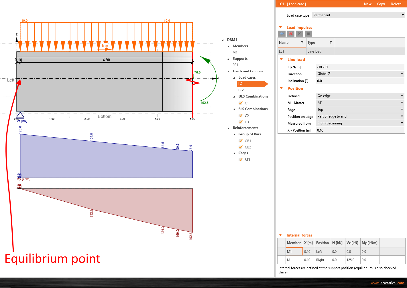
Viga simple con apoyo en el extremo
Para este modelo, el punto de equilibrio se sitúa sobre el apoyo en el extremo de la viga. Para alcanzar el equilibrio, debe definir las cargas como en el modelo global y los valores de las fuerzas internas. En este caso particular, las fuerzas internas que deben introducirse son, de hecho, las reacciones en el apoyo tomadas del modelo global, y establecidas como fuerza cortante vertical. Para verificar la corrección de los resultados, consulte el diagrama de fuerzas internas que se muestra en la ventana gráfica principal de la aplicación. El software calcula automáticamente los valores de las fuerzas internas hasta el extremo recortado de la viga, por lo que al final debería ver los mismos resultados para este punto exacto que en el modelo global.
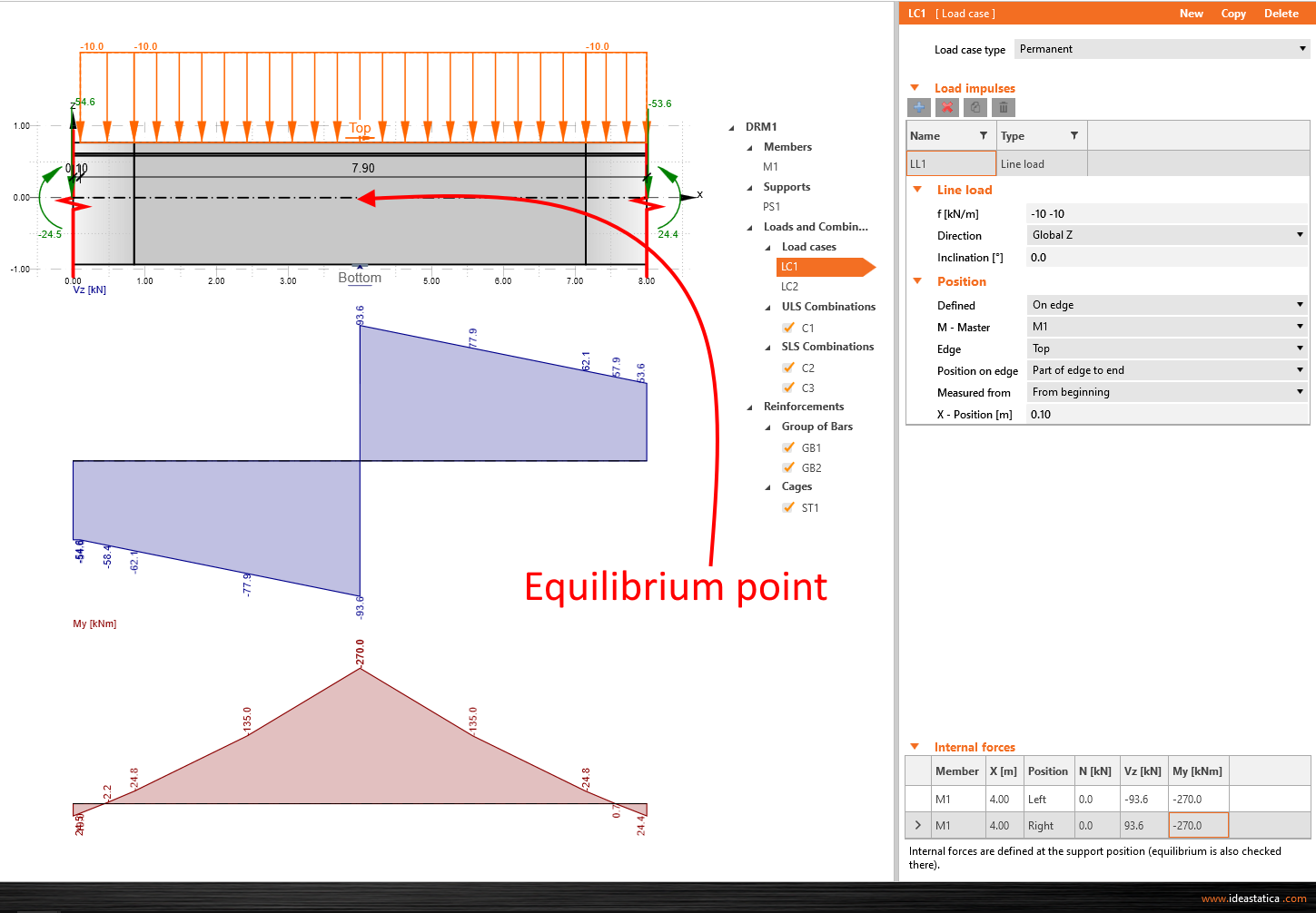
Viga simple con apoyo intermedio
Para este tipo, el punto de equilibrio se sitúa nuevamente sobre el apoyo, y el enfoque es casi el mismo que en el caso del ejemplo de apoyo en el extremo. La única diferencia está en la introducción de las fuerzas internas. Debe establecerlas desde ambos lados del apoyo. La corrección puede verificarse observando el diagrama de fuerzas internas y la reacción en el apoyo; este valor debe ser igual a la suma absoluta de las fuerzas cortantes.
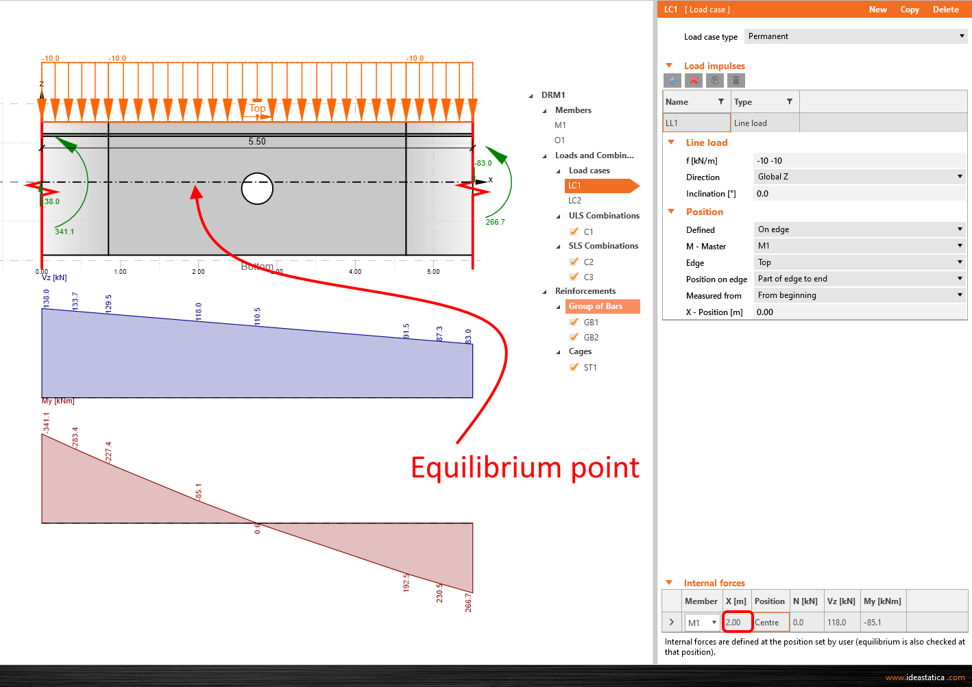
Recorte de viga simple
La última opción del modelo de viga simple. Se aplican las mismas reglas que en los ejemplos anteriores. Solo que en este caso, puede ajustar manualmente la posición del punto de equilibrio utilizando las coordenadas X relacionadas con el sistema de coordenadas global. Por lo tanto, introduce los valores únicamente para este punto específico.
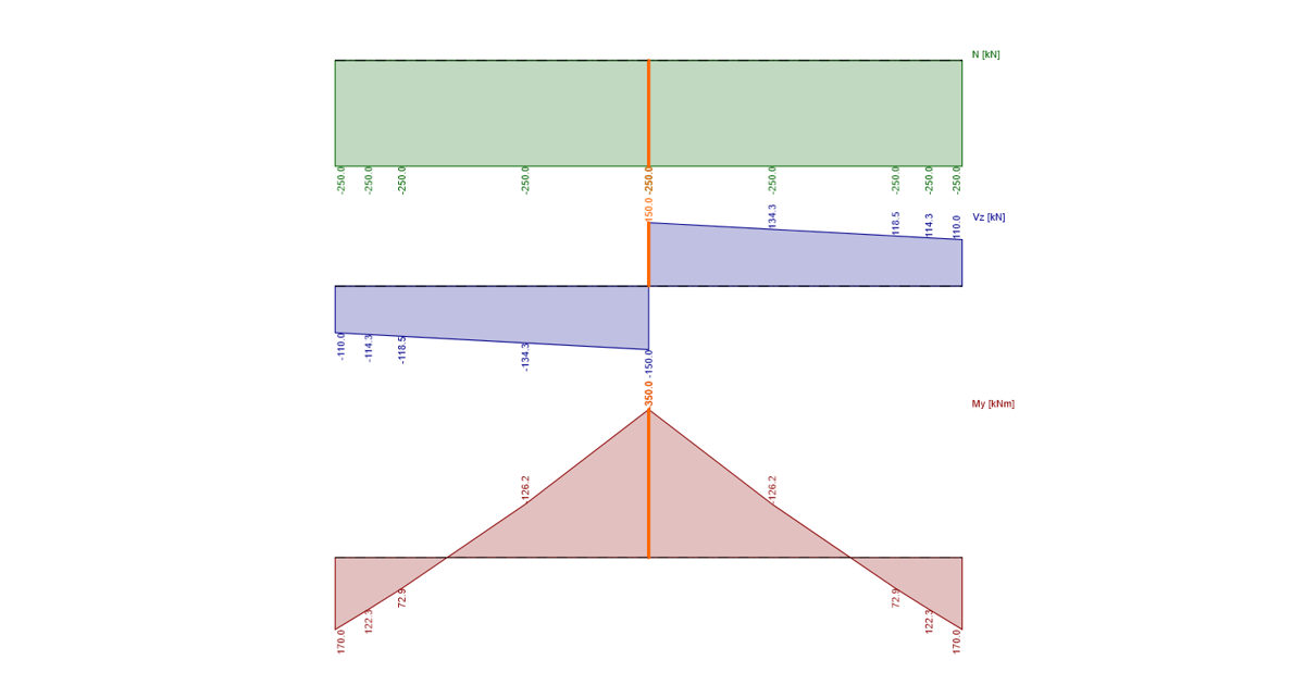
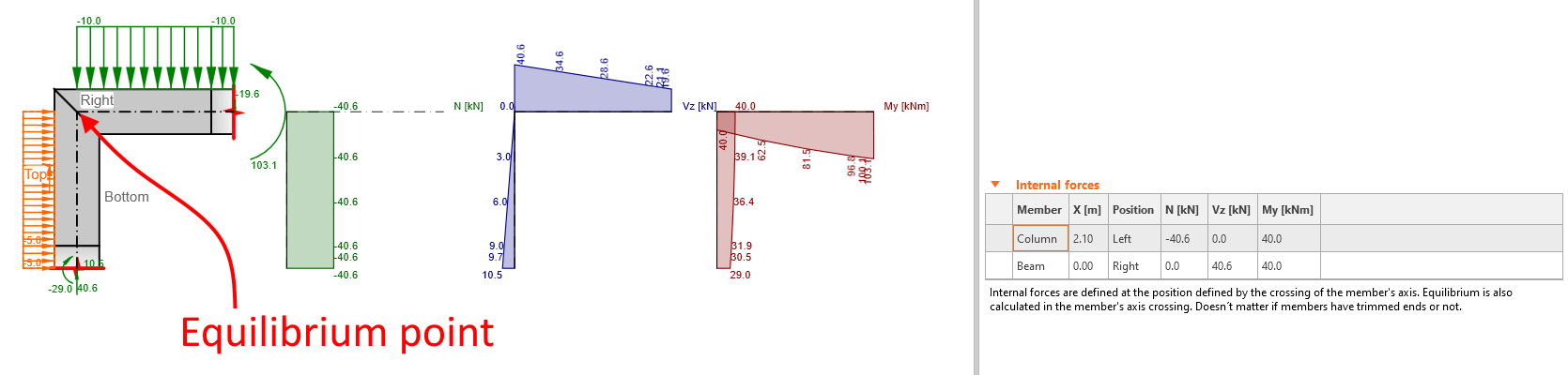
Junta en rodilla
En el caso de una junta de pórtico, el punto de equilibrio, es decir, la posición de la definición de las fuerzas internas, se encuentra en el cruce de los ejes de los elementos: el nodo en el modelo global. Ni la inclinación ni el tipo de junta afectan a la definición del punto de equilibrio.
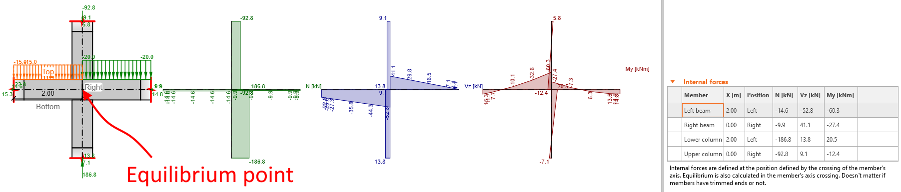
Junta en cruz
Las condiciones de introducción de las fuerzas internas son las mismas que para la junta en rodilla.
Ejemplo práctico
Para una mejor comprensión, vea la demostración. En el siguiente vídeo, verá cómo insertar las fuerzas obtenidas del modelo global. El ejemplo del vídeo está incluido en un webinar transmitido anteriormente: Verificación normativa de un pilar con ménsula según ACI usando IDEA StatiCa.