Descripción general de los impulsos de carga en la aplicación Detail
Se pueden definir cuatro tipos de impulsos de carga para las regiones de discontinuidad de hormigón armado:
- Carga puntual
- Carga lineal
- Carga superficial
- Peso propio
Ahora, veamos cada una de las opciones.
Carga puntual
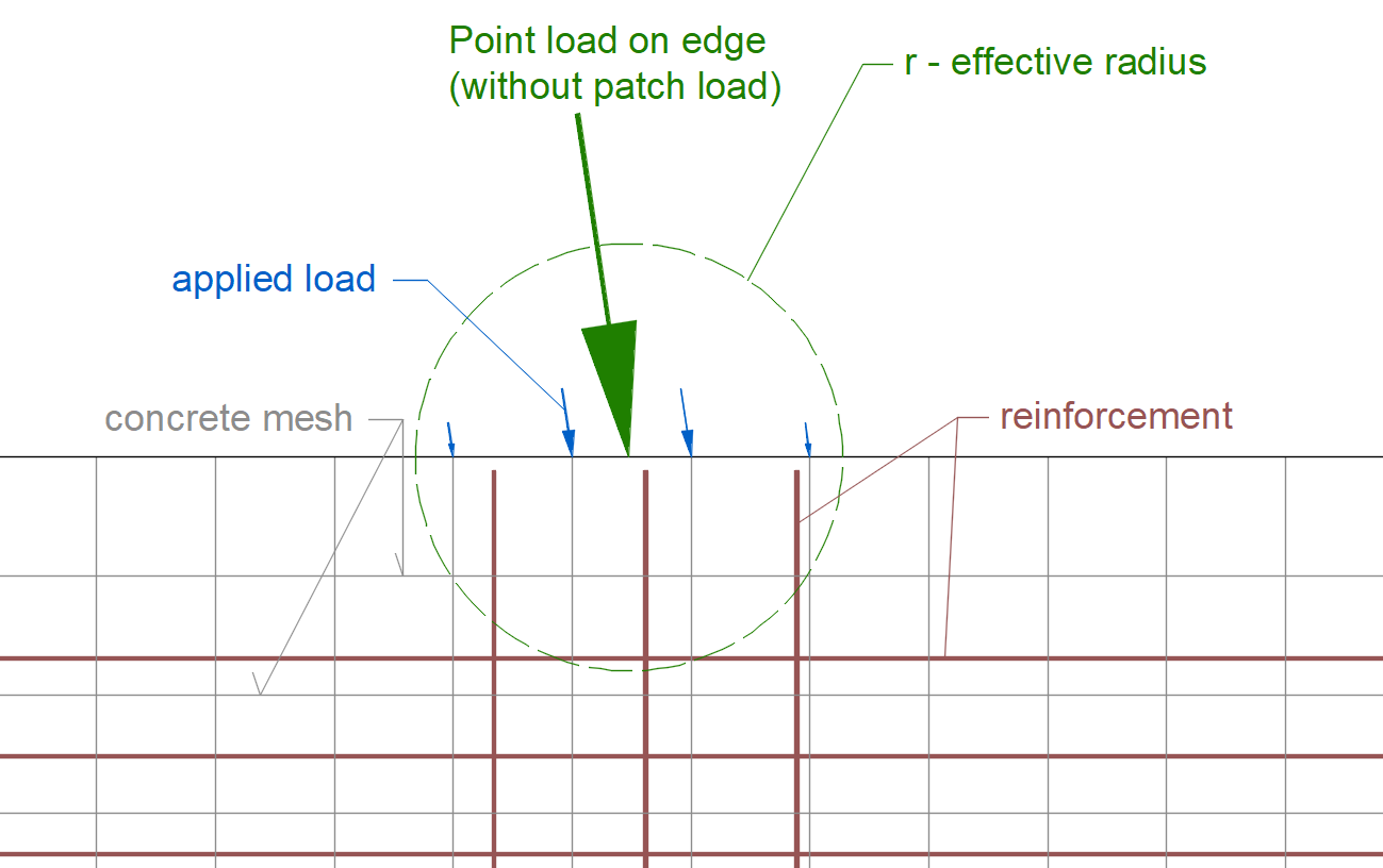
Este simple impulso de carga se define por su valor, dirección, inclinación, posición y radio efectivo. La forma en que se configura una carga puntual puede influir en el método de aplicación de la carga al modelo.
La primera opción es establecer la carga en el borde. Véase la figura a continuación.
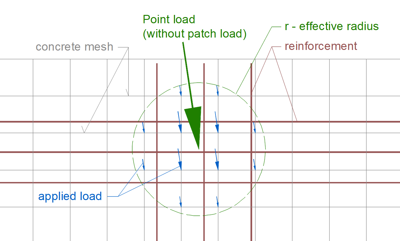
La segunda opción es establecer la carga generalmente en el modelo. El valor de cada carga aplicada se calcula mediante una media ponderada donde el peso es la distancia desde el punto de aplicación. En otras palabras, las cargas aplicadas se distribuyen de forma variable, no uniforme.
La tercera opción es ajustar la carga a la carga de parche - uno de los dispositivos de transferencia de carga, utilizando la funcionalidad en la sección de Geometría.
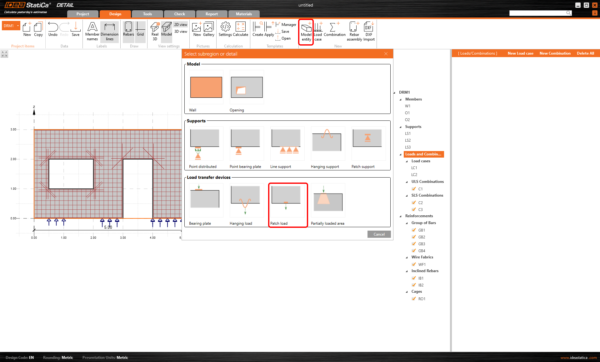
La aplicación de la carga se muestra en la imagen a continuación.
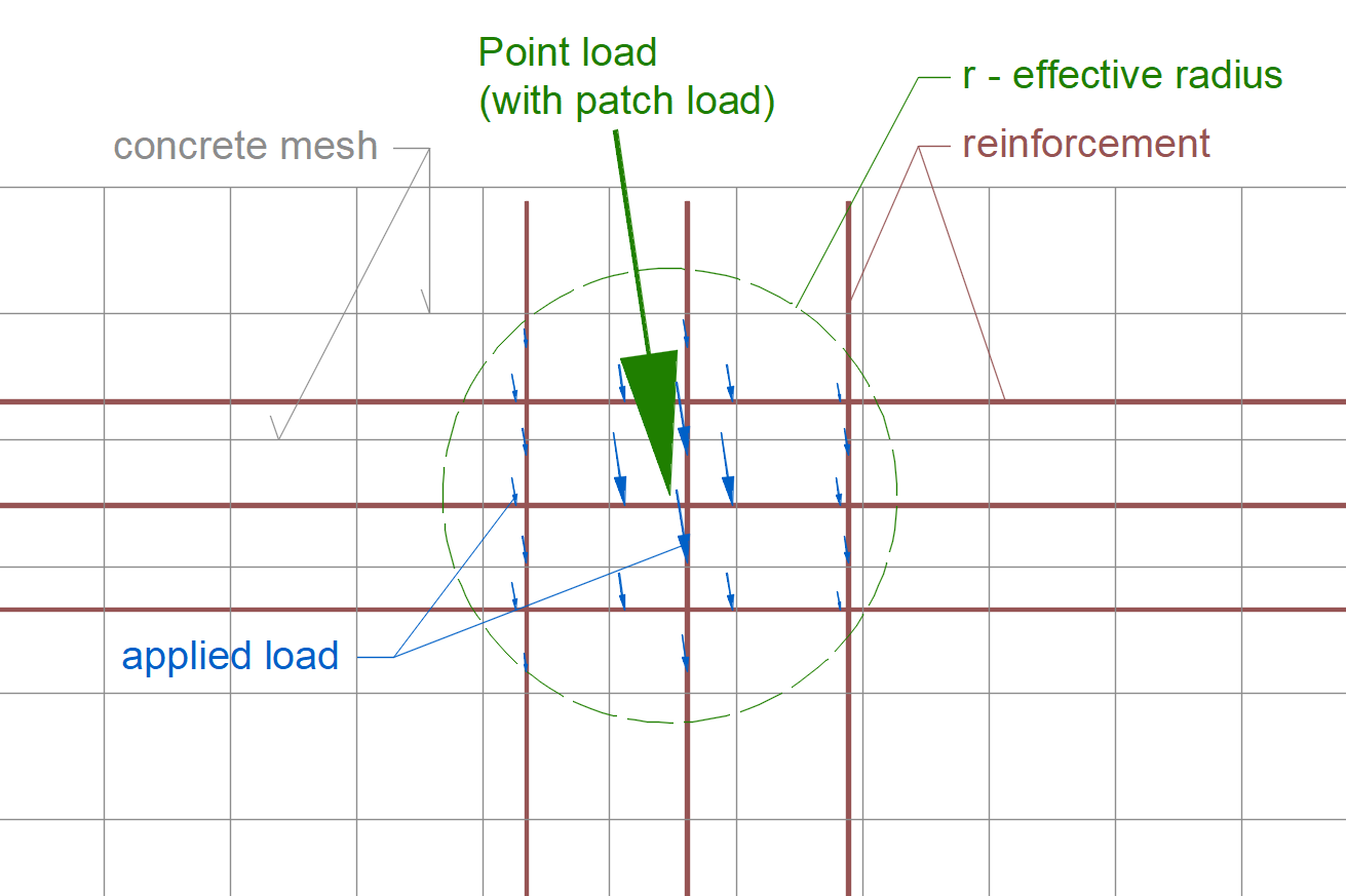
Comparemos las imágenes de la carga colocada en el modelo y configurada mediante la carga de parche. Sin carga de parche, la carga puntual se aplica a los elementos de la malla de hormigón. Por otro lado, con la carga de parche, la carga puntual se aplica directamente a las barras de armadura.
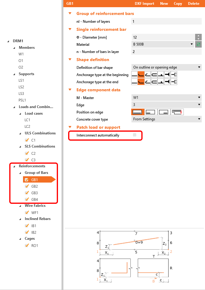
La carga de parche puede conectarse automáticamente a la armadura adyacente mediante el software. Sin embargo, para ello, debe activar la casilla de verificación de las barras correspondientes en la sección de Armadura.
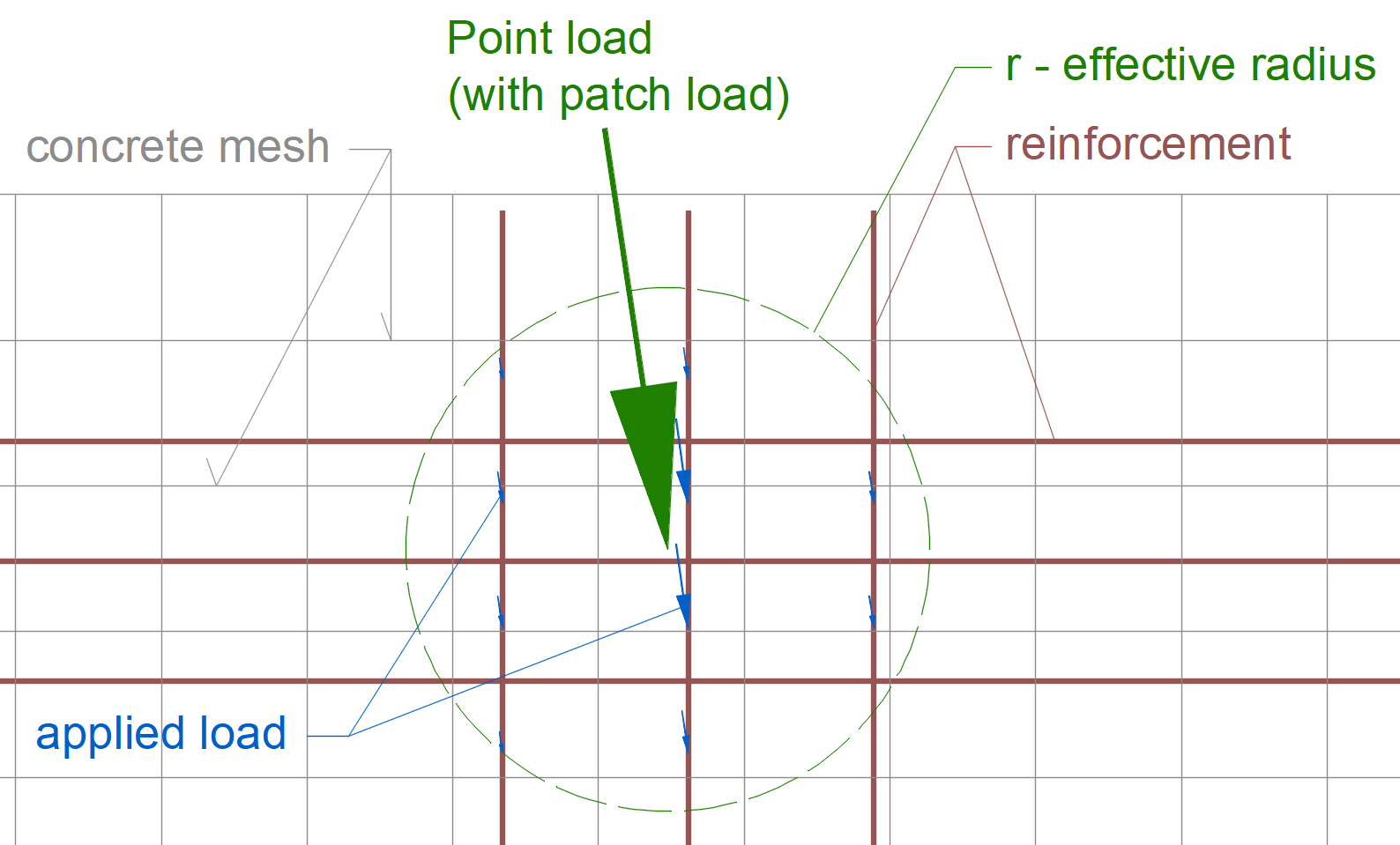
En la figura a continuación, puede ver el caso en que la armadura horizontal fue excluida del área de carga de parche y, por tanto, no se consideró para la transmisión de carga.
Las cargas puntuales también pueden transferirse a través de otros dispositivos de transmisión de carga, como placas de apoyo, cargas colgantes y más. ¿Desea saber más al respecto? Lea el artículo Componentes de apoyo y transmisión de carga.
El principio principal es que las cargas puntuales se aplican al modelo mediante enlaces elásticos con diferentes rigideces. Las rigideces se evalúan mediante medias ponderadas basadas en la longitud de los enlaces. Estos enlaces están conectados a los puntos de la malla de hormigón o de armadura (donde se dibujaron las flechas azules) y transfieren las cargas a la estructura.
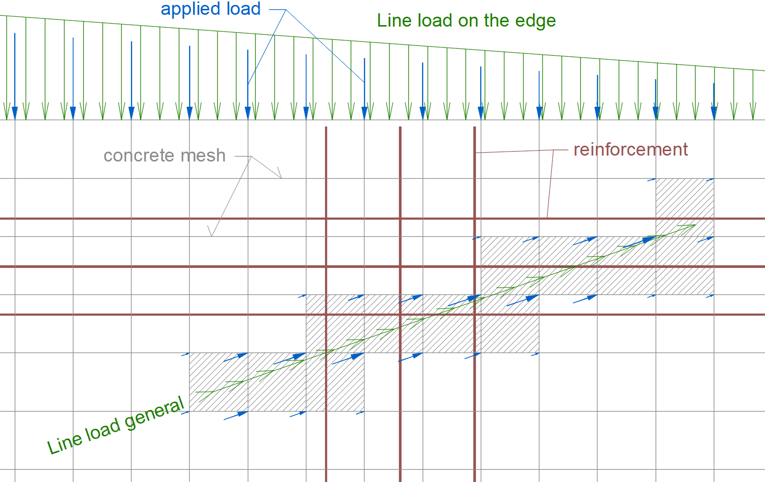
Carga lineal
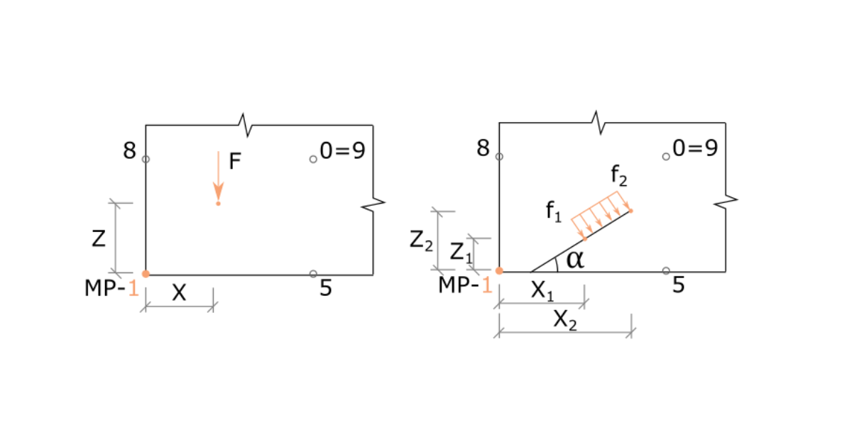
La carga lineal puede definirse como uniforme o trapezoidal. El tipo utilizado depende de la definición numérica de la carga. Al aplicar la carga lineal uniforme, simplemente introduzca un único valor en la celda correspondiente de la ventana de datos. No obstante, si necesita especificar la carga trapezoidal, introduzca los valores en uno y otro extremo de la carga. Véanse los ejemplos prácticos:
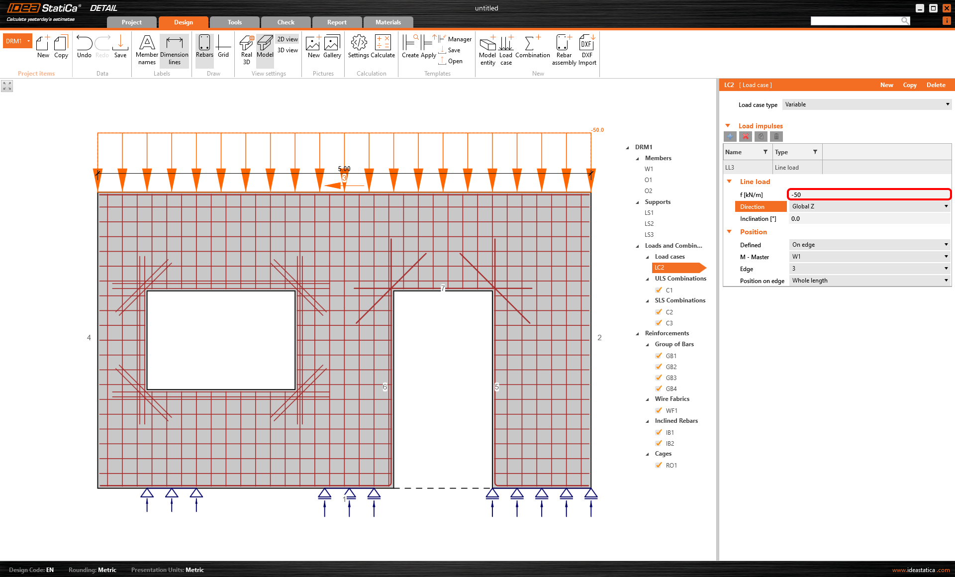
Ejemplo de carga uniforme
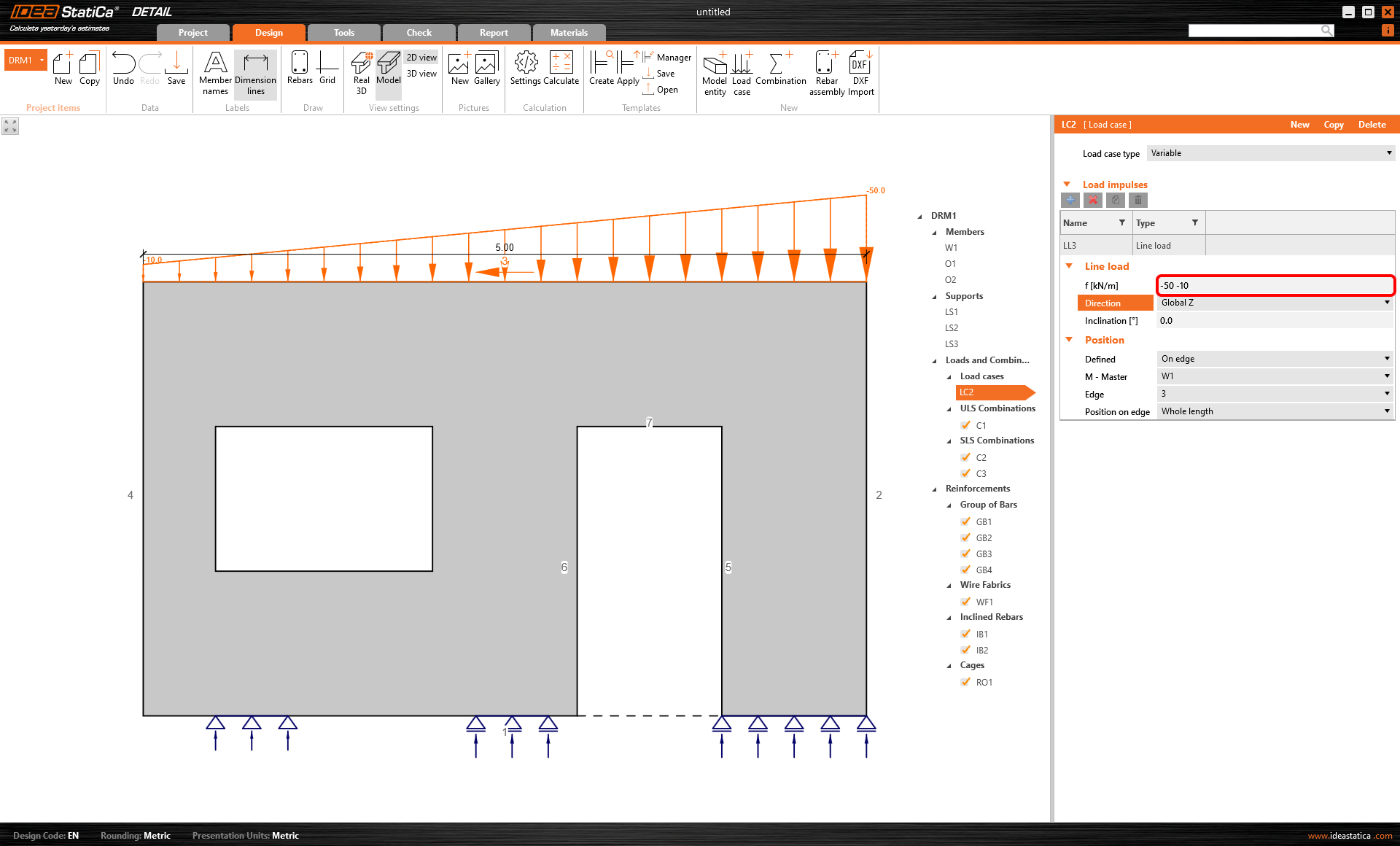
Ejemplo de carga trapezoidal
El principio de aplicación de la carga es casi idéntico al de la carga puntual.
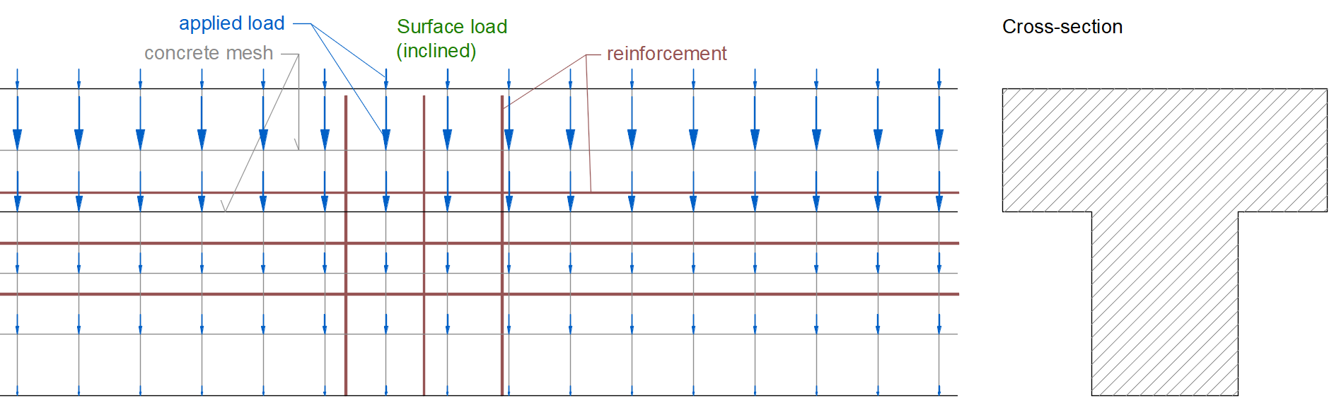
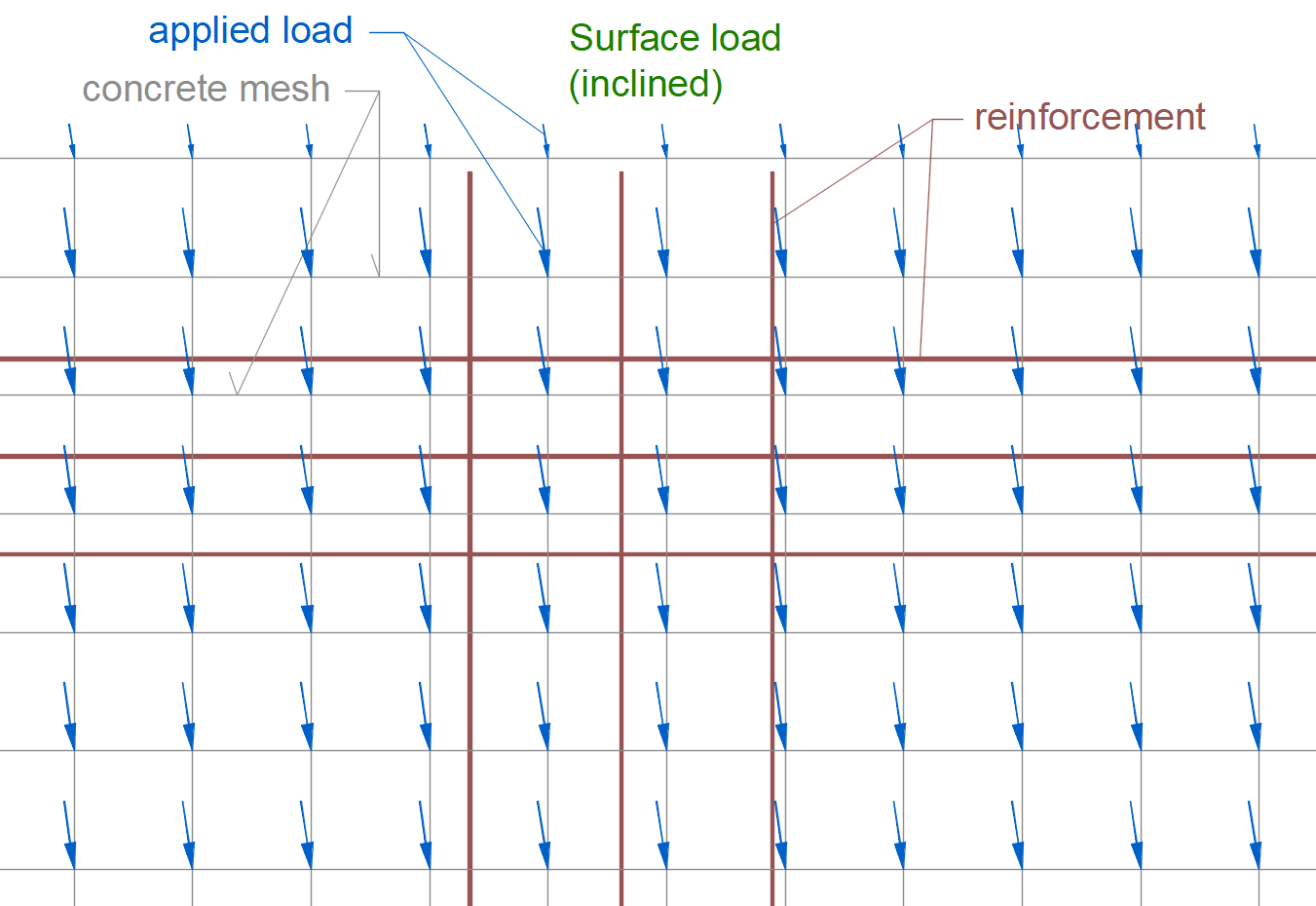
Carga superficial
La aplicación de la carga superficial funciona de la misma manera. Se aplica a los nodos de los elementos de la malla de la estructura de hormigón.
Peso propio
El peso propio es una versión de la carga superficial. Las intensidades se calculan automáticamente según la sección transversal seleccionada.