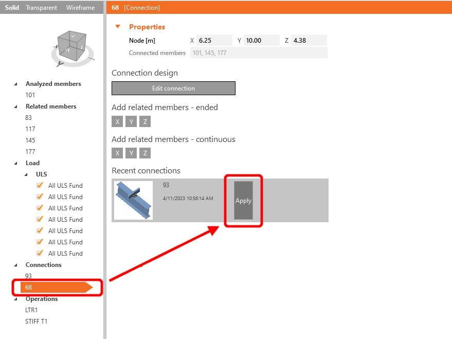
As we have similar joints on both sides of the member, you can copy the operations from the first joint to another by clicking Apply.
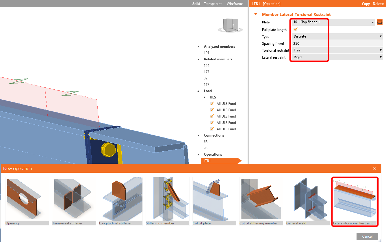
Before starting the analysis, firstly left-click on the U-member, add operation Lateral Restraint, and set up the values according to the picture.
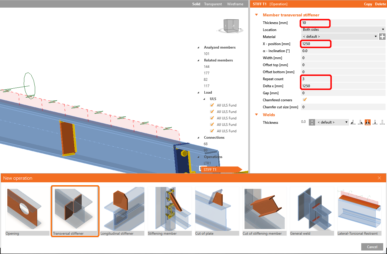
In the next step add operation Stiffeners the same way as in the previous step, and configure the values as shown
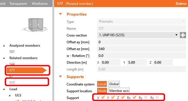
For the realistic behavior of the related members, restrict the supports of the connecting purlins to X, Y, Z, and Rx.
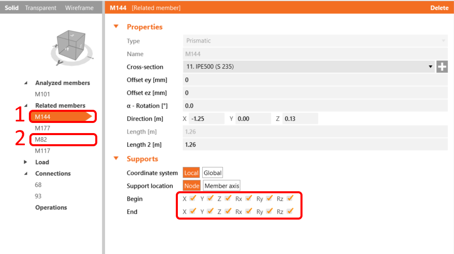
Do the same for the I-profiles frame members; restrict them to X, Y, Z, and Rx, Ry, Rz.
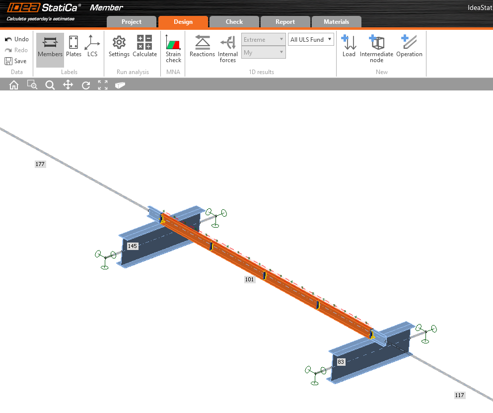
Now the member is ready to be analyzed.
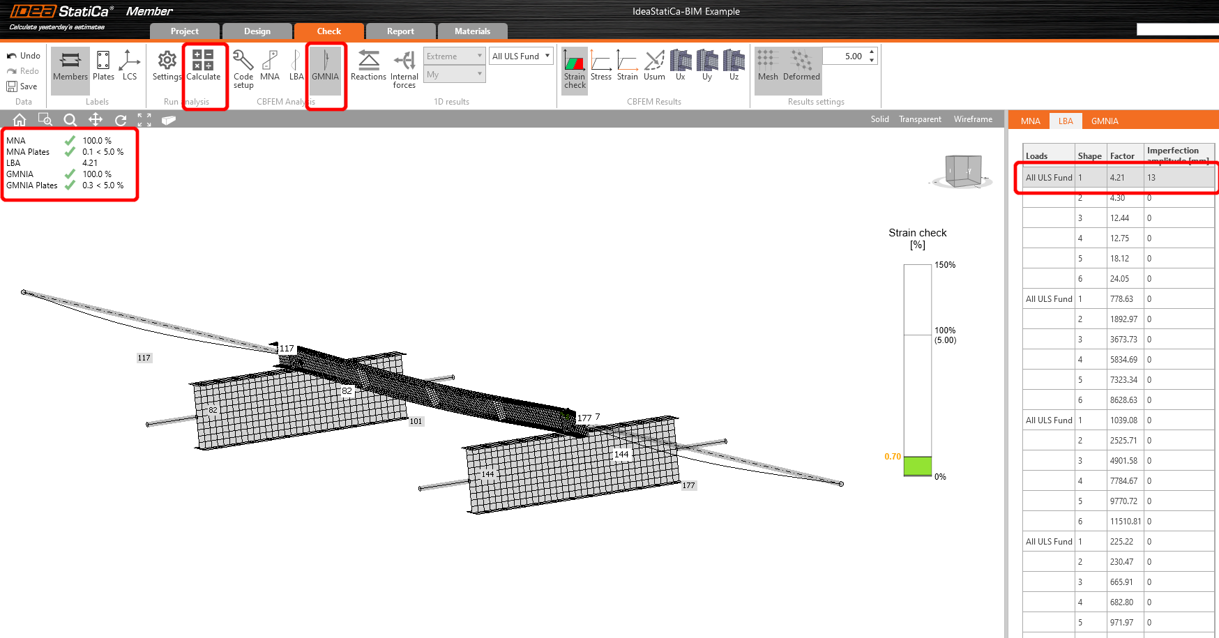
Select the Tab Check and run the MNA (materially non-linear) Analysis.
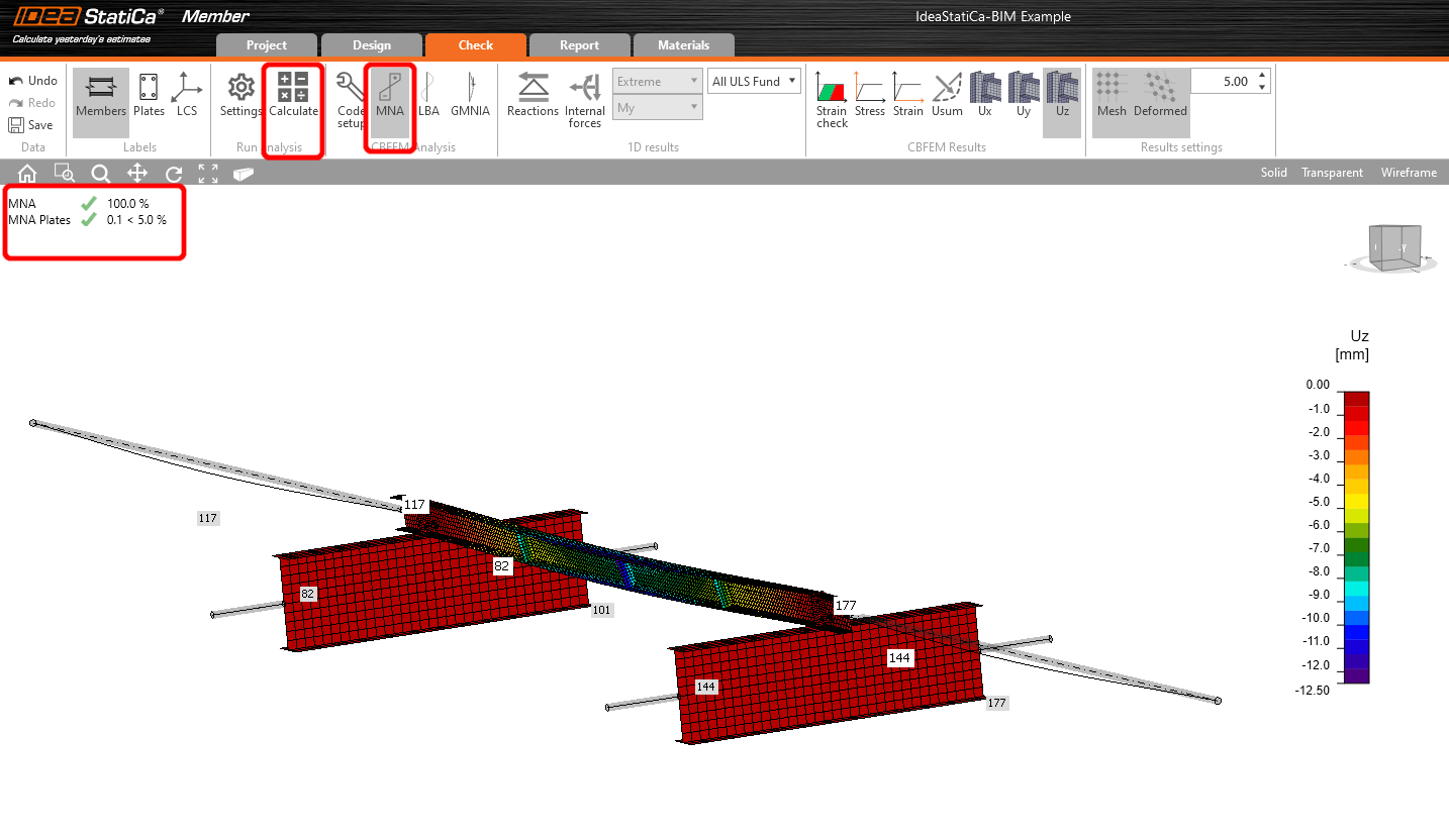
The second analysis is LBA (lateral buckling analysis), where we get a critical factor of less than 15.
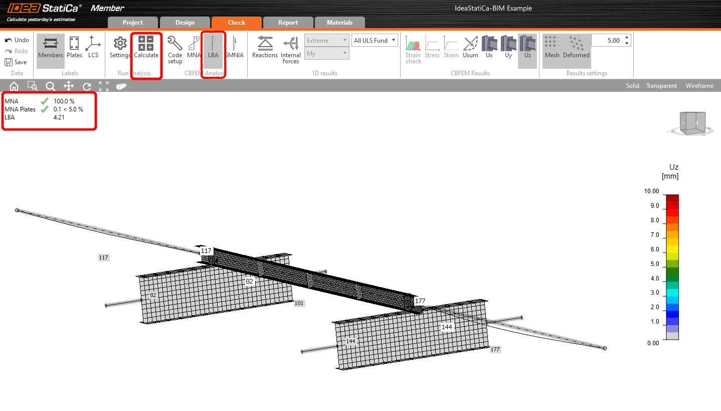
This result shows the necessity of running the GMNIA (geometrically and materially non-linear analysis).
Because lateral-torsional buckling is investigated, factor k0 = 0.5 may be used. Amplitude 0.5 • 5000 / 200 = 12,5 mm is applied to the first buckling mode.
Click on the imperfection field for the critical buckling factor, and fill the value we calculated above in the row, as shown in the following picture. Then you can run the last GMNIA (geometrically and materially non-linear) analysis.
Read more about:
- Member stability in IDEA StatiCa Member.
- Lateral torsional buckling