Vigas de acoplamiento e IDEA StatiCa
Las vigas de acoplamiento se añaden típicamente a una estructura para mejorar su resistencia a las fuerzas laterales. Unen dos elementos separados e independientes (como muros de cortante) para añadir rigidez al sistema global. Son generalmente cortas y gruesas, similares a las vigas de gran canto. En los edificios de hormigón, en particular, adoptan la forma de vigas de hormigón, que suelen ser uno de los elementos más críticos.
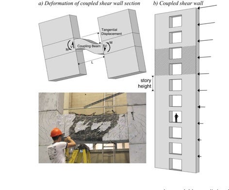
Figura 1. Fisher, Andrew W., et al. "Response of Heavily Reinforced High-Strength Concrete Coupling Beams." ACI Structural Journal, vol. 114, no. 6, Nov.-Dec. 2017, pp. 1483+. Gale Academic OneFile, link.gale.com/apps/doc/A558752923/AONE?u=anon~dff1dbd&sid=googleScholar&xid=6f6988a6. Accessed 1 Nov. 2022.
Las vigas de acoplamiento tienen dos funciones en la mayoría de los edificios. En primer lugar, la viga acopla dos muros de cortante para aumentar el momento de resistencia. Si se tienen dos muros de cortante no acoplados, la fuerza ejercida desde un lado de un muro no influiría en el segundo muro porque no están conectados por vigas con una sección transversal rectangular típica. Esto significa que la fuerza ejercida afectará solo a un muro, lo que podría provocar movimientos independientes del otro. Esto reduce significativamente la integridad estructural del edificio. Por el contrario, al acoplar los dos, se reduce la tensión que atrae cada muro distribuyendo las fuerzas de un muro al otro a través del sistema de vigas. Las vigas de acoplamiento también distribuyen la fuerza lateral a lo largo de la longitud del segundo muro, lo que distribuye aún más la tracción a lo largo del elemento y mejora la resistencia global de los elementos estructurales.
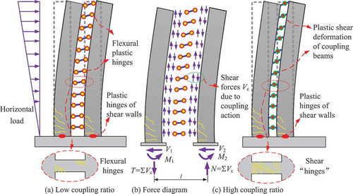
Figura 2. Yang Liu, Hai Chen, Zi-Xiong Guo & Hong-Song Hu (2020) Seismic performance of subassemblies with composite wall and replaceable steel coupling beam, Journal of Asian Architecture and Building Engineering, 19:2, 123-137, DOI: 10.1080/13467581.2020.1718679
La segunda función de una viga de acoplamiento es actuar como fuente de disipación de energía durante tensiones extremas. Por ejemplo, si se produce un terremoto, un edificio debe ser resistente a la presión. Para ser resistente, una estructura no puede ser demasiado rígida. De lo contrario, si se produjera un terremoto (por ejemplo), ese edificio se rompería en el pilar del muro y colapsaría. Por el contrario, una ligera flexibilidad bajo presiones extraordinarias significa que la estructura es mucho más capaz de mantener la integridad estructural esencial bajo presión.
Una viga de acoplamiento refuerza el diseño de un edificio en su conjunto y está diseñada para ceder primero con el fin de preservar las partes más vitales del edificio si experimenta tensiones extremas. Al incorporar el movimiento del edificio en el diseño de las vigas, los ingenieros estructurales crean estructuras más estables y seguras.
Modelos de vigas de acoplamiento
El modelo puede dividirse según el mecanismo de disipación de energía en función de la relación de acoplamiento baja/alta. Debido a la cuantía de armadura y principalmente a la relación longitud/altura, el mecanismo de rótulas plásticas se desarrollará en las vigas de acoplamiento. El Modelo 1 a continuación tiene una relación de acoplamiento baja y l/h >4 y puede diseñarse según la teoría de vigas, y las rótulas plásticas aparecerán en los extremos de la viga. Los Modelos 2 y 3 a continuación tienen una relación de acoplamiento alta con l/h<2 y esto conduce a diferentes mecanismos de rótulas plásticas causados por la fuerza cortante. Los modelos han sido modelados y sometidos a verificación normativa en IDEA StatiCa Detail y IDEA StatiCa Member.
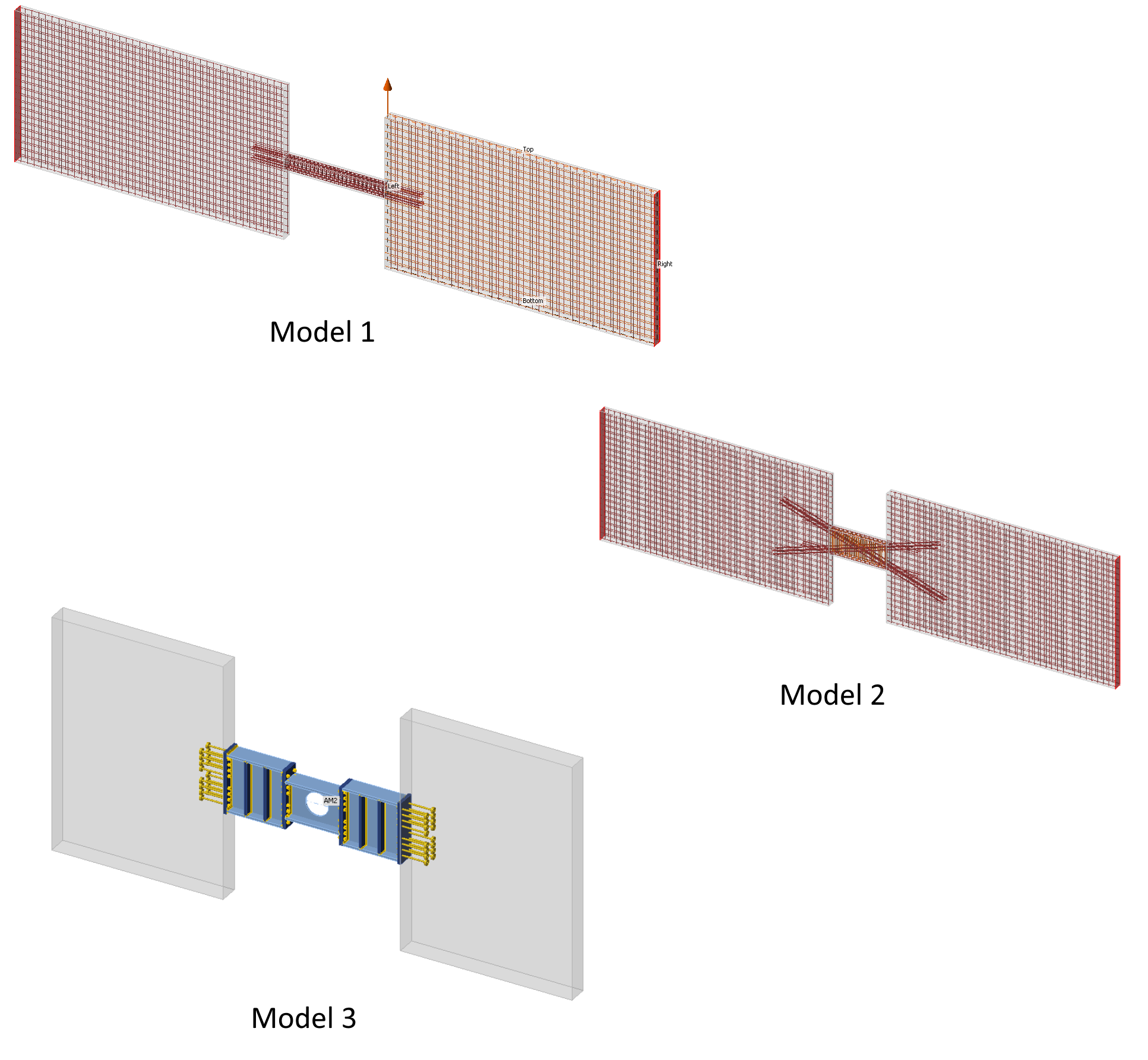
Figura 3. Tipos de viga de acoplamiento según la relación de acoplamiento y el desarrollo de rótulas plásticas
Cargas y optimización topológica
Los muros de cortante pueden servir como un sistema estructural eficaz para resistir cargas laterales, como terremotos o viento, en edificios de gran altura. Las vigas de acoplamiento que conectan estos muros, que se comportan de forma independiente en cada planta, pueden mejorar la capacidad de resistencia lateral del edificio y disipar energía. Las fuerzas internas inducidas por estas cargas dinámicas son principalmente fuerzas en el plano. Las tensiones principales revelan las zonas más solicitadas de la estructura y nos ayudan a comprender la disposición correcta de la armadura. La optimización topológica utiliza el método de biela y tirante, que es familiar para los ingenieros estructurales.

Figura 4.1. Fuerzas internas y optimización topológica para relación de acoplamiento baja
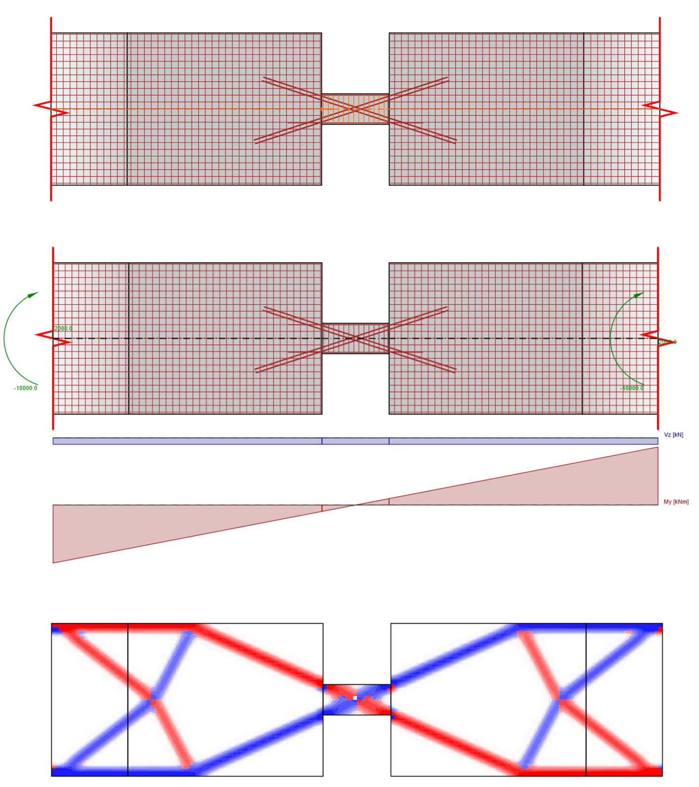
Figura 4.2. Fuerzas internas y optimización topológica para relación de acoplamiento alta
Mecanismo de rótulas plásticas
Las rótulas plásticas se desarrollan en función de la relación de acoplamiento. Las vigas de acoplamiento de gran canto con una relación de acoplamiento alta desarrollan rótulas plásticas de cortante ubicadas en el centro de la viga. Por otro lado, una viga con una relación de acoplamiento baja aprovecha la baja rigidez a flexión de las vigas para crear las rótulas plásticas en los extremos de las vigas de acoplamiento.
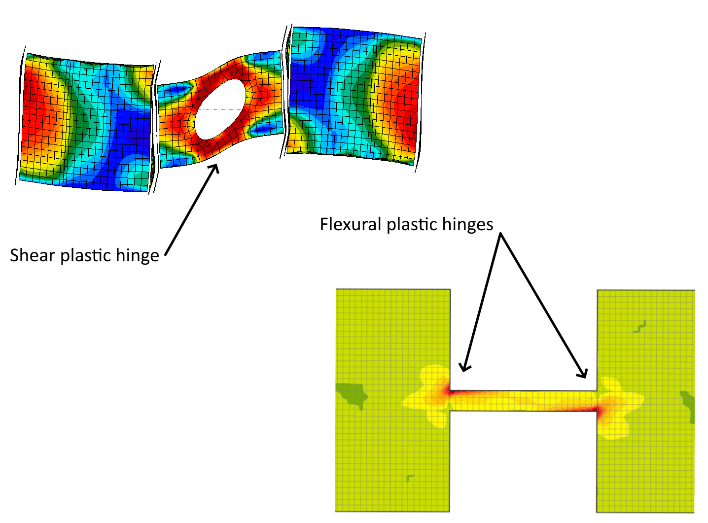
Figura 5. Rótulas plásticas de cortante y flexión
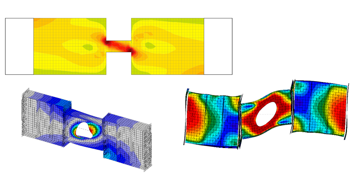
Singularidades vs. tensión
La esquina viva creada en la unión de la viga de acoplamiento y el muro de cortante genera un pico de tensión local que distorsiona los resultados del modelo. Este pico está causado por las singularidades en el punto de la esquina reentrante viva. La cuestión es cómo tratar estos picos en los propios modelos. Más información aquí.
Verificación normativa de vigas de acoplamiento
La verificación normativa, según la normativa, es la parte principal del procedimiento de análisis. Analicemos qué podemos obtener de los resultados para vigas de acoplamiento de hormigón e híbridas utilizando IDEA StatiCa Detail y IDEA StatiCa Member.
Vigas de acoplamiento – relación de acoplamiento baja
Debido a su detallado relativamente sencillo y facilidad de construcción, la viga de acoplamiento de hormigón armado convencional es el tipo de viga de acoplamiento más ampliamente utilizado en el diseño de edificios. En zonas de bajo riesgo sísmico, las vigas de acoplamiento de hormigón armado convencionales a veces se dimensionan más anchas que los muros de cortante de conexión en edificios de losa plana. Sin embargo, la viga de acoplamiento de hormigón armado convencional no proporciona buenas capacidades de disipación de energía bajo tensiones cortantes cíclicas elevadas, y se presentan fenómenos significativos de "estrangulamiento" en su respuesta histerética. El fallo por cortante diagonal y el fallo por deslizamiento cortante no son evitables en este tipo de viga de acoplamiento, incluso con un detallado de armadura transversal de separación reducida.
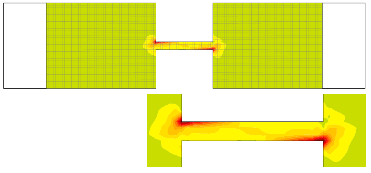
Figura 6. Tensión principal en compresión

Figura 7. Tensión en las barras de armadura
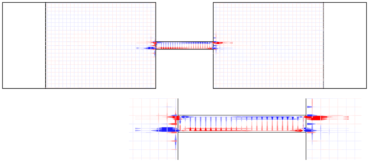
Figura 8. Tensión de adherencia de anclaje en la armadura
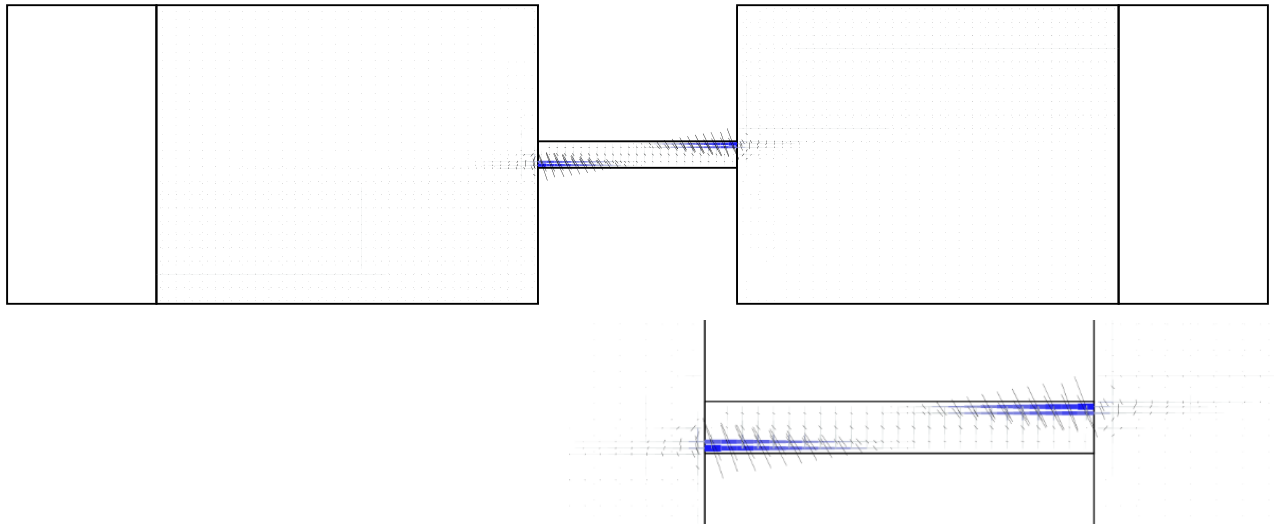
Figura 9. Desarrollo y dirección de fisuras

Figura 10. Deflexión no lineal
Vigas de acoplamiento – relación de acoplamiento alta
Las vigas de acoplamiento de hormigón armado con armadura diagonal se reconocen como el tipo más eficaz de viga de armadura para proporcionar un comportamiento dúctil con una excelente capacidad de disipación de energía, especialmente cuando la relación luz/canto es inferior a dos. Aunque las vigas de acoplamiento con armadura diagonal presentan una excelente rigidez y capacidades de disipación de energía altamente dúctiles, algunos problemas de constructibilidad limitan su aplicación.

Figura 11. Tensión principal en compresión
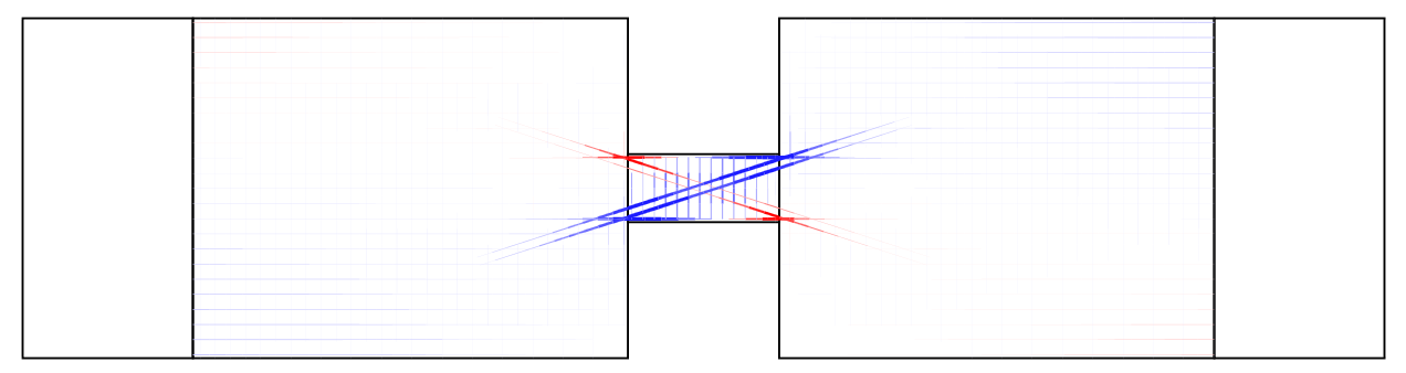
Figura 12. Tensión en las barras de armadura
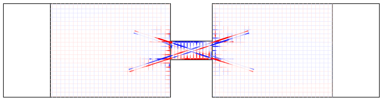
Figura 13. Tensión de adherencia de anclaje en la armadura

Figura 14. Desarrollo y dirección de fisuras
Figura 15. Deflexión no lineal
La viga de acoplamiento híbrida
Las vigas de acoplamiento son difíciles y costosas en tiempo de reparar una vez dañadas tras un terremoto. Recientemente, varios investigadores desarrollaron varios tipos de vigas de acoplamiento reemplazables que pueden repararse después del terremoto. Una preocupación principal para la viga de acoplamiento reemplazable es mejorar su capacidad de autocentrado para reducir el desplazamiento residual de las estructuras.
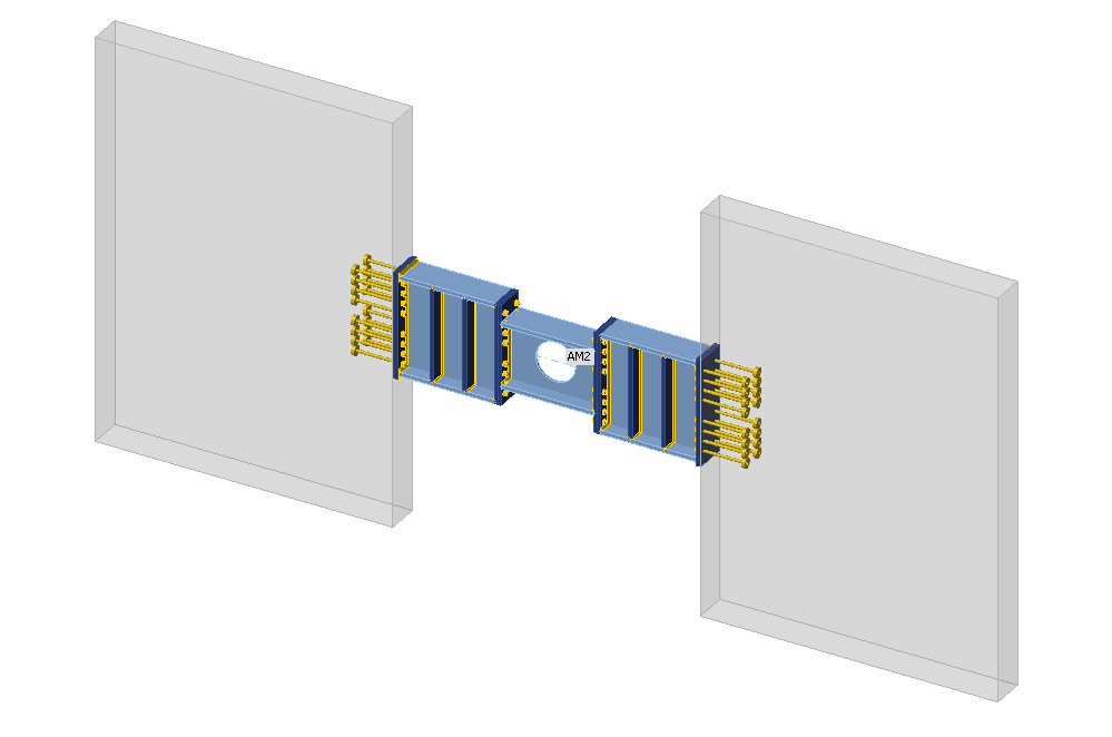
Figura 16. Modelo de vigas de acoplamiento híbridas
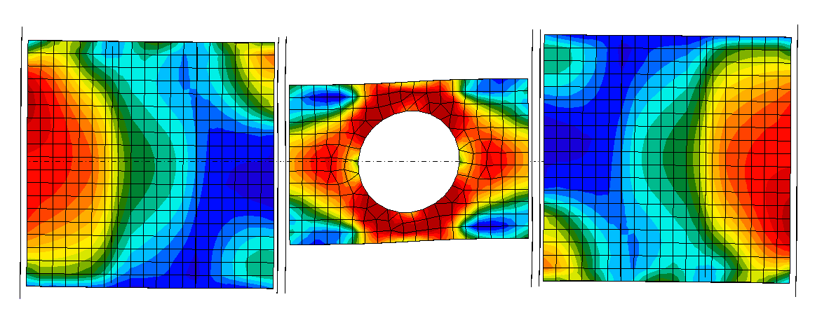
Figura 17. Tensión equivalente
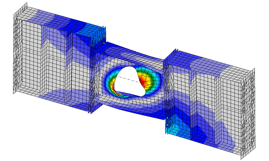
Figura 18. Primera forma de pandeo lineal
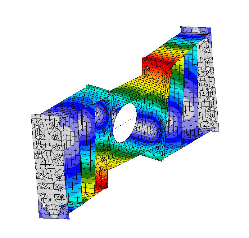
Figura 19. Segunda forma de pandeo lineal
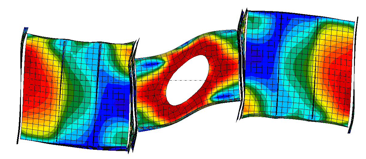
Figura 20. GMNIA y forma deformada
Conclusión
Cada tipo de viga de acoplamiento adoptado por la industria tiene sus propios beneficios y limitaciones. Sin embargo, no existe un único tipo de viga de acoplamiento aplicable a todos los casos en el diseño de edificios. La viga de acoplamiento de hormigón armado convencional suele ser la más viable y económica siempre que la tensión cortante de la viga sea baja y la viga esté controlada por flexión. Cuando las relaciones luz-canto de la viga de acoplamiento son pequeñas, se esperan tensiones cortantes elevadas. Las limitaciones de estos tipos de vigas de acoplamiento y los requisitos de longitud de anclaje asociados deben tenerse en cuenta al elegir un tipo de viga de acoplamiento adecuado para proyectos específicos. Como siempre, el proyectista debe considerar las preferencias del equipo de construcción siempre que sea posible, ya que muchos contratistas tendrán opiniones variadas relacionadas con cada metodología.
Más información sobre vigas de acoplamiento e IDEA StatiCa
