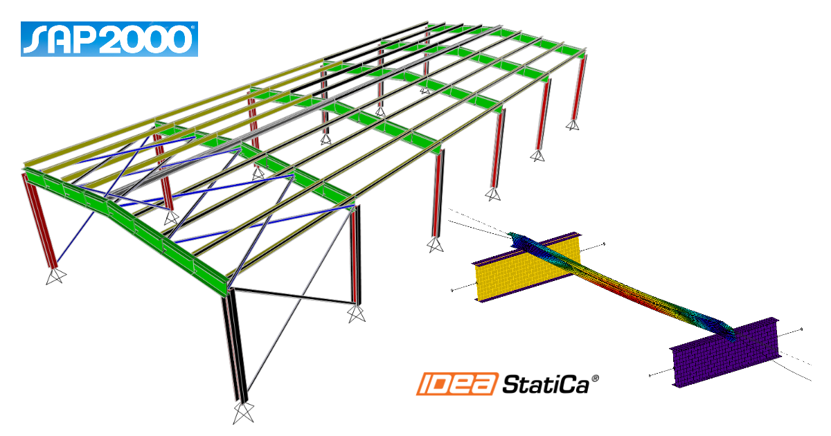
SAP2000 BIM-Verknüpfung für die Stahlbauteil-Bemessung (EN)
So aktivieren Sie die Verknüpfung
BIM-Verknüpfung Aktivierung für SAP2000 (v23 und neuer)
BIM-Verknüpfung Aktivierung für SAP2000 (v22 und älter)
So verwenden Sie IDEA StatiCa Checkbot
Laden Sie das beigefügte Projekt herunter, öffnen Sie es in SAP2000 und führen Sie die Berechnung aus, um die Schnittgrößen über die Struktur zu erhalten.
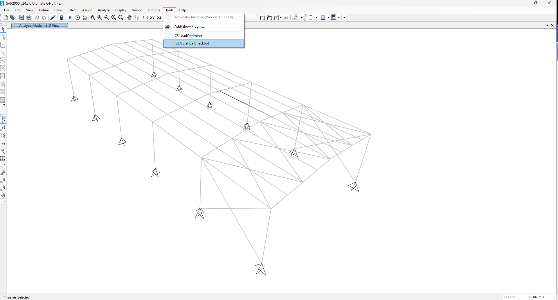
Die BIM-Verknüpfung ist bereits integriert. Sie befindet sich im oberen Menüband unter Tools -> IDEA StatiCa Checkbot.
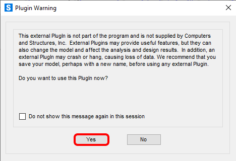
Danach wird eine informative Benachrichtigung von SAP2000 angezeigt. Bestätigen Sie diese mit OK.
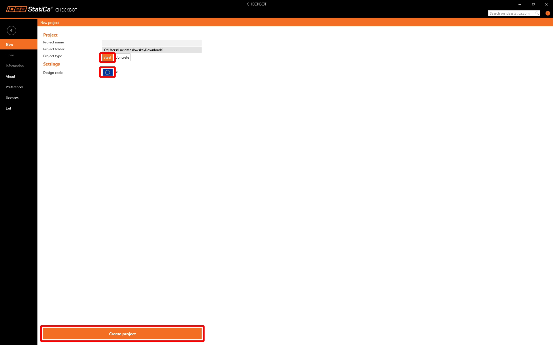
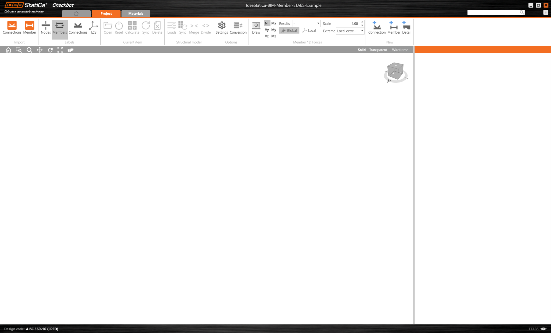
Anschließend wird die Checkbot-Anwendung gestartet.
Wählen Sie die Option Neu mit dem Projekttyp Stahl und der Bemessungsnorm EN. Klicken Sie dann auf Projekt erstellen.
Das neue Checkbot-Projekt ist bereit, Bauteile aus SAP2000 zu importieren.
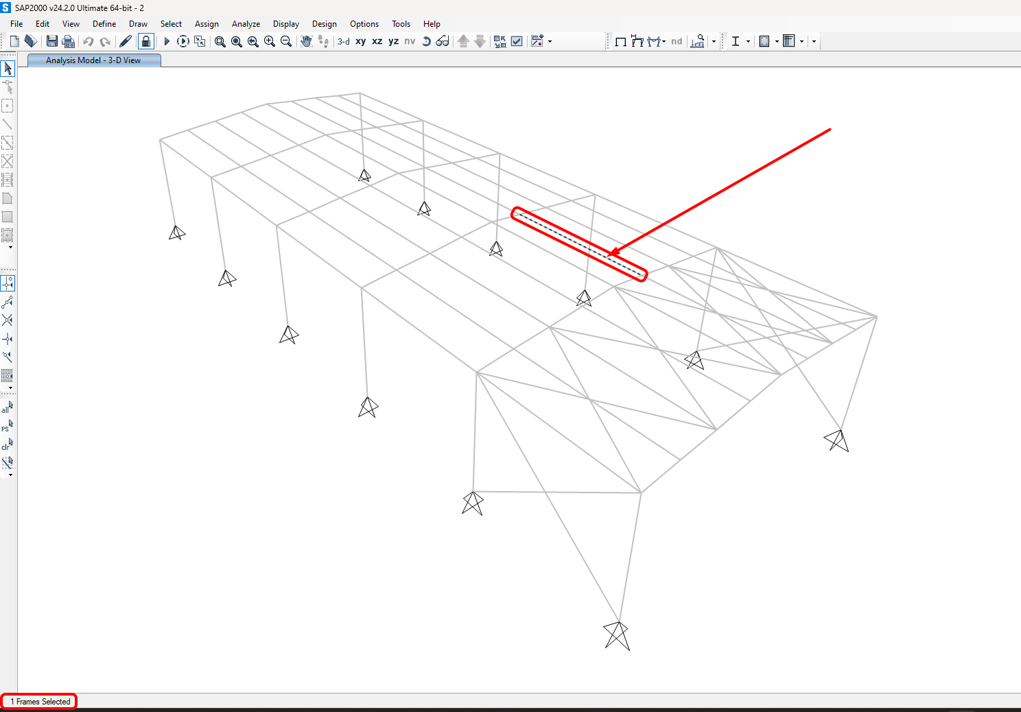
Wählen Sie in SAP2000 eines der inneren Bauteile aus, wie in der Abbildung dargestellt.
Import
Wählen Sie dann in Checkbot Member.
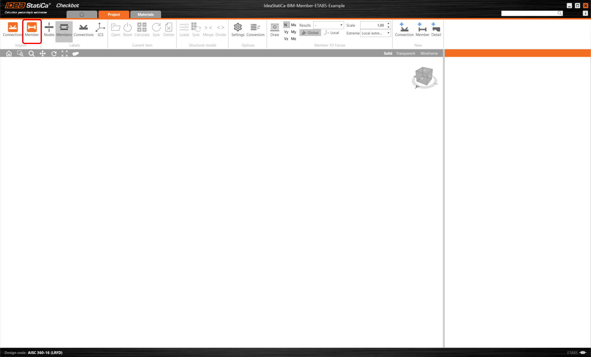
Dadurch werden der Träger und seine Lasteffekte in Checkbot importiert – mit den exakten Koordinaten, Ausrichtungen und Querschnittsabmessungen gemäß dem FEA/BIM-Modell.
Bitte beachten Sie, dass Ihre Knoten- und Bauteillnummerierung abweichen kann.
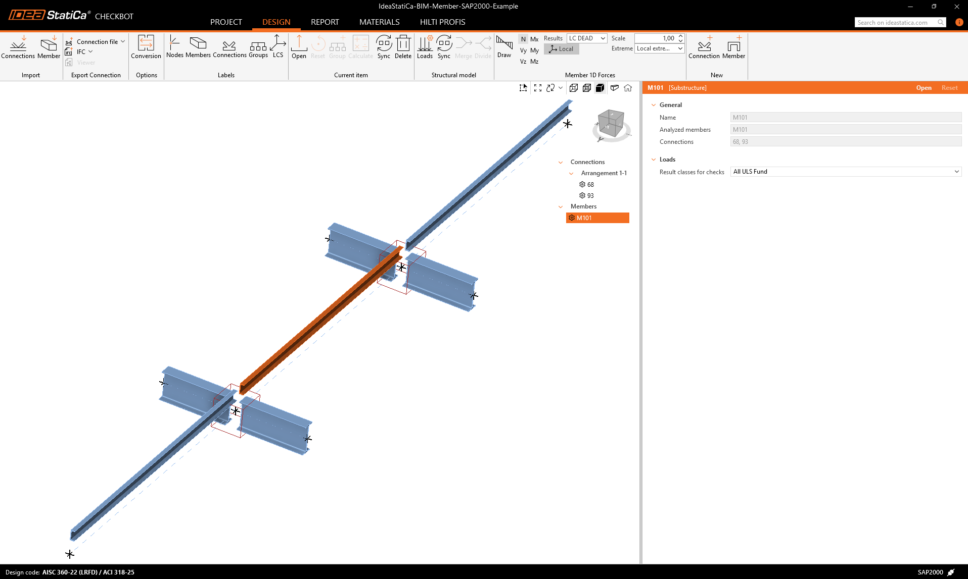
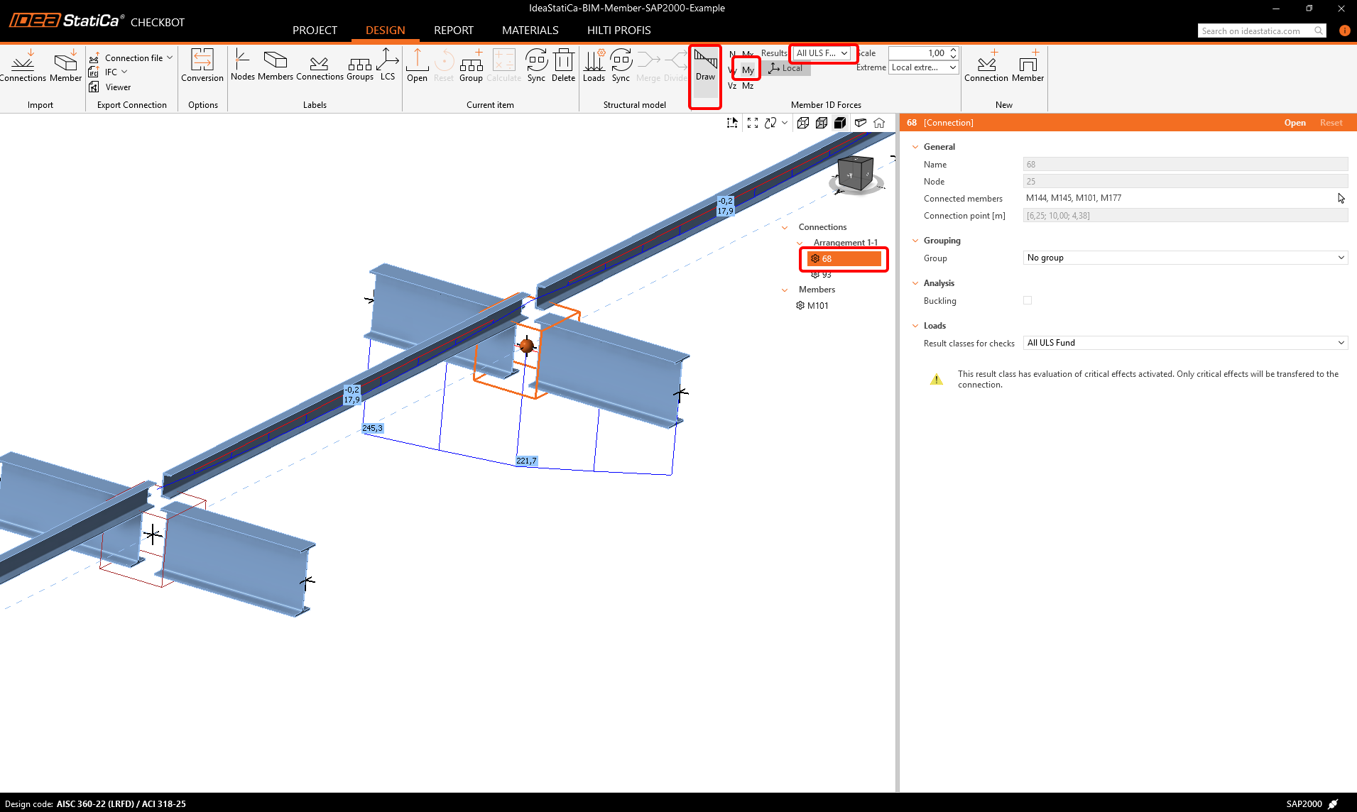
Wie zu sehen ist, wurde das ausgewählte Bauteil mit allen zugehörigen Bauteilen importiert.
Sie können die Schnittgrößen überprüfen. Wählen Sie Draw, dann die gewünschte Schnittgröße und Kombination, klicken Sie anschließend mit der linken Maustaste auf das Verbindungsfeld und folgen Sie den nachstehenden Schritten im Bild.
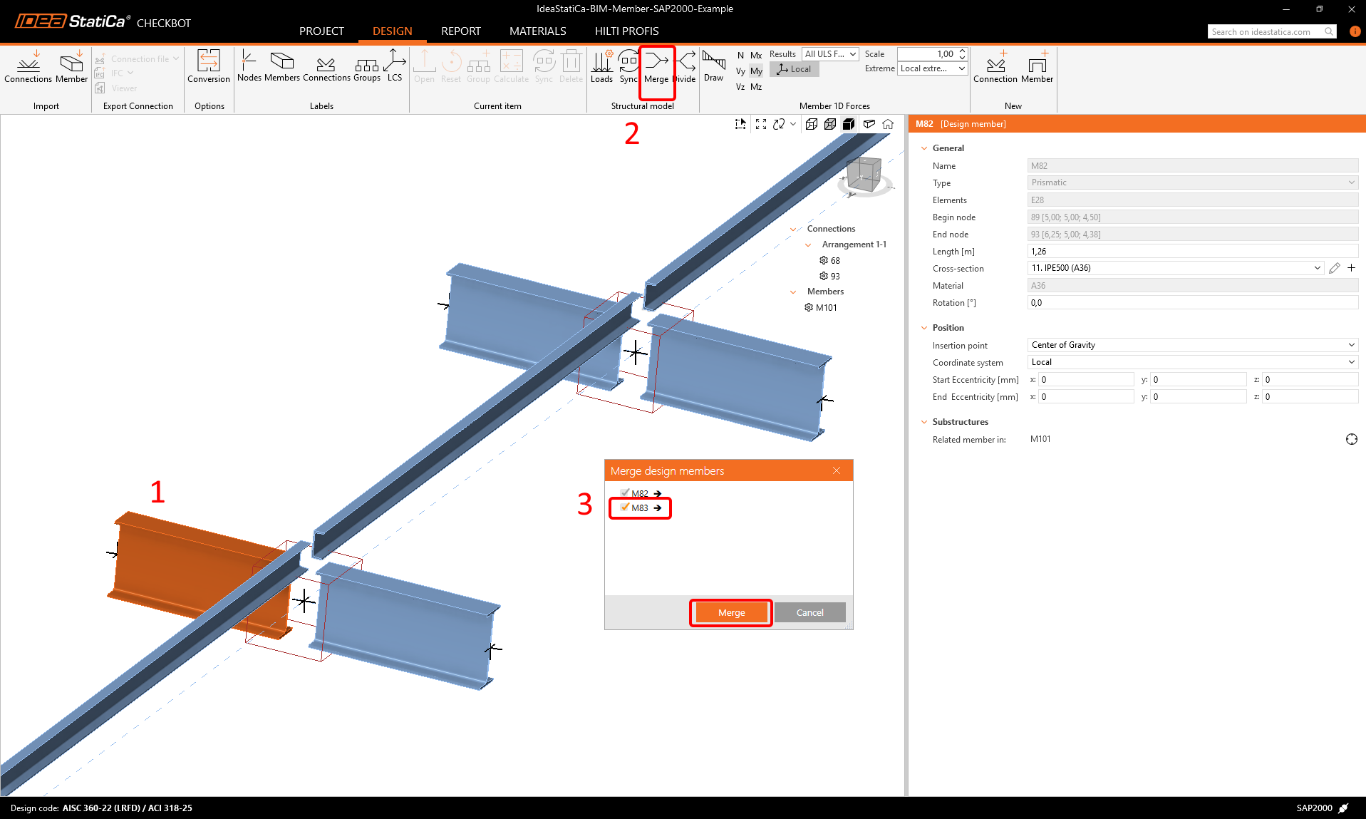
Bauteile können direkt in Checkbot zusammengeführt werden; in der Member-Anwendung werden sie dann als ein einziges durchgehendes Element behandelt.
Führen Sie beide senkrecht angrenzenden Bauteile zusammen. Klicken Sie mit der linken Maustaste auf das I-Profil M-82, wählen Sie die Zusammenführungs-Operation, aktivieren Sie dann das Kontrollkästchen M83 im Zusammenführungsfenster und folgen Sie den im Bild gezeigten Schritten.
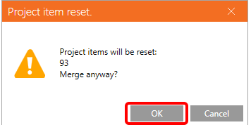
In diesem Fenster wird ein informativer Hinweis zur durchzuführenden Operation angezeigt; bestätigen Sie diesen.
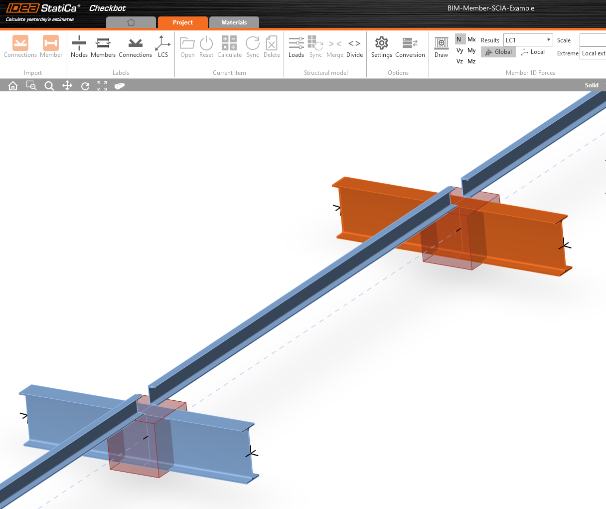
Führen Sie dieselbe Zusammenführungsaktion für eine weitere Gruppe von I-Profilen durch. Nach den Änderungen sollte unser Modell wie im folgenden Bild aussehen.
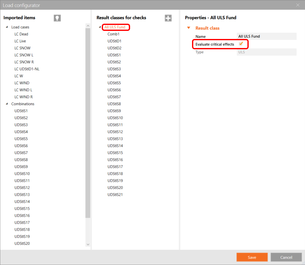
Sie können steuern, welcher Lastfall oder welche Kombination in die Member-Anwendung geladen wird, indem Sie auf „Loads" klicken und die Ergebnisklassen für die Nachweise verwalten.
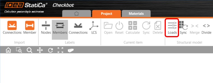
Im Load Configurator können Sie Lastfälle für die Member-Anwendung hinzufügen. Bitte beachten Sie, dass standardmäßig die Funktion Evaluate critical results aktiviert ist, die kritische Kombinationen herausfiltert, um die Berechnung zu beschleunigen. Sie können diese Funktion deaktivieren, sodass alle Kombinationen in die Berechnung einbezogen werden.
Bauteil-Modul
Jetzt können wir die Member-Anwendung öffnen. Klicken Sie einfach mit der linken Maustaste auf Open.
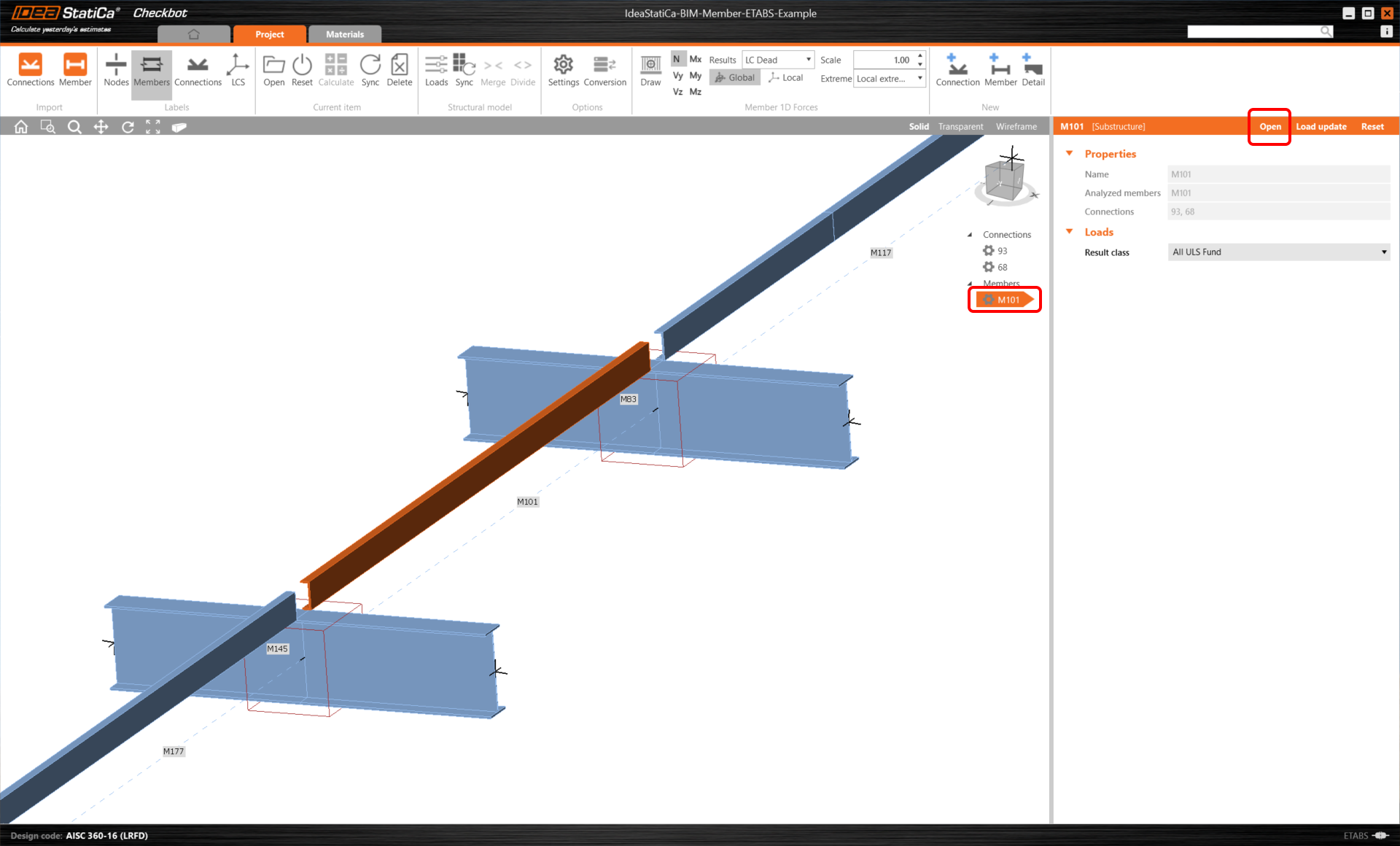
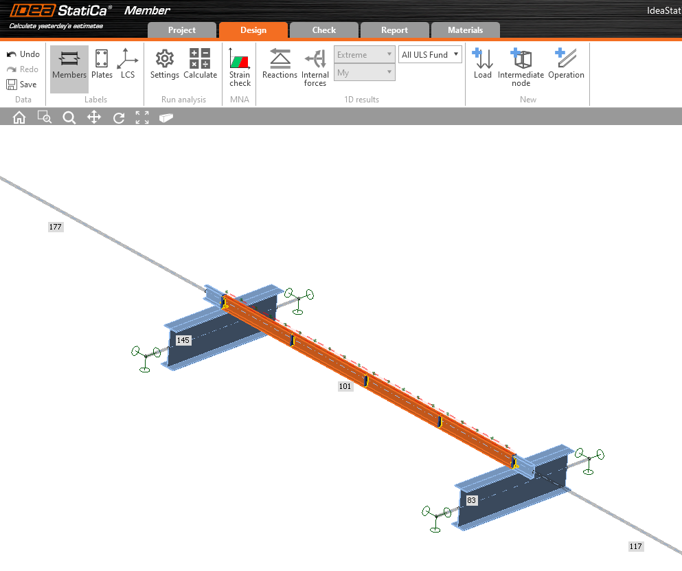
Hier sehen Sie unsere Member-Anwendung.
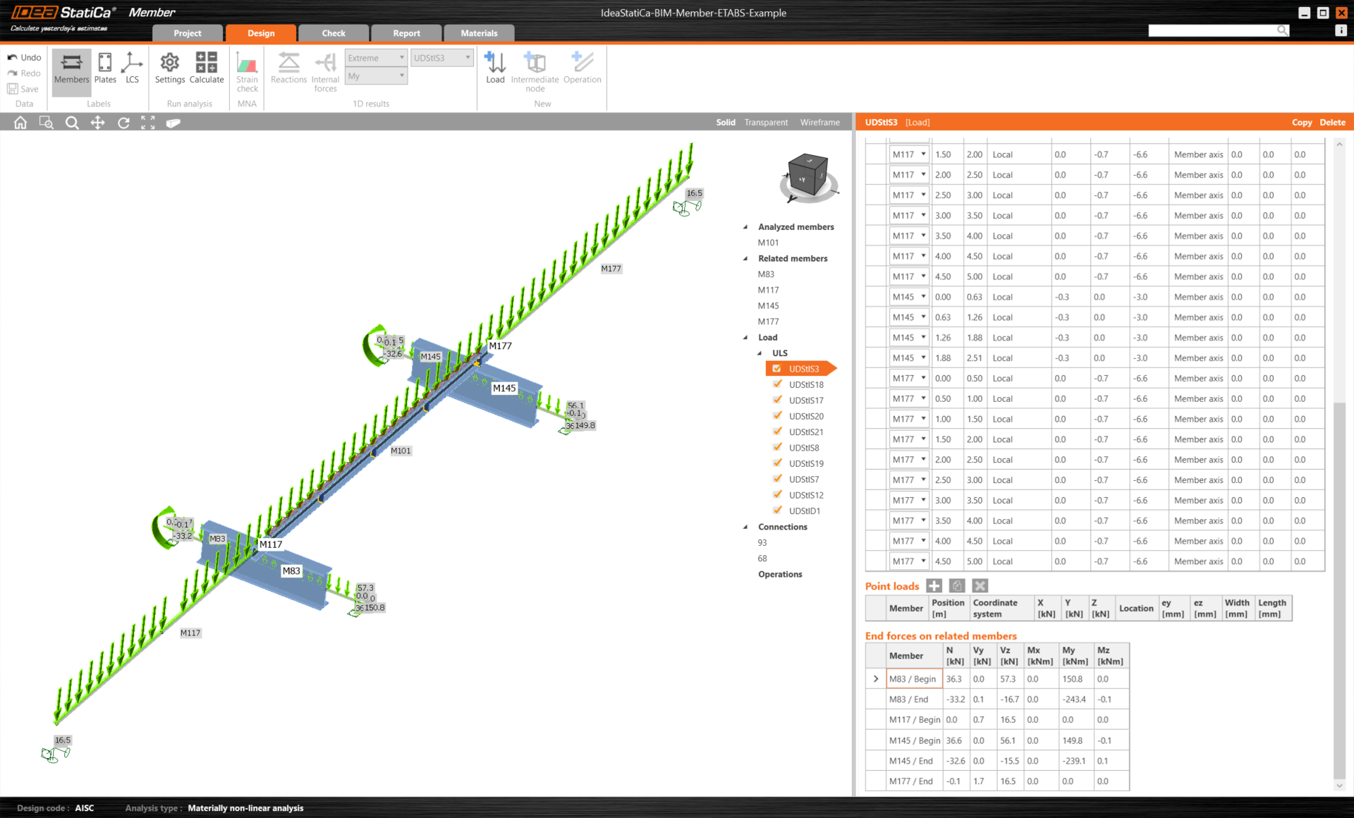
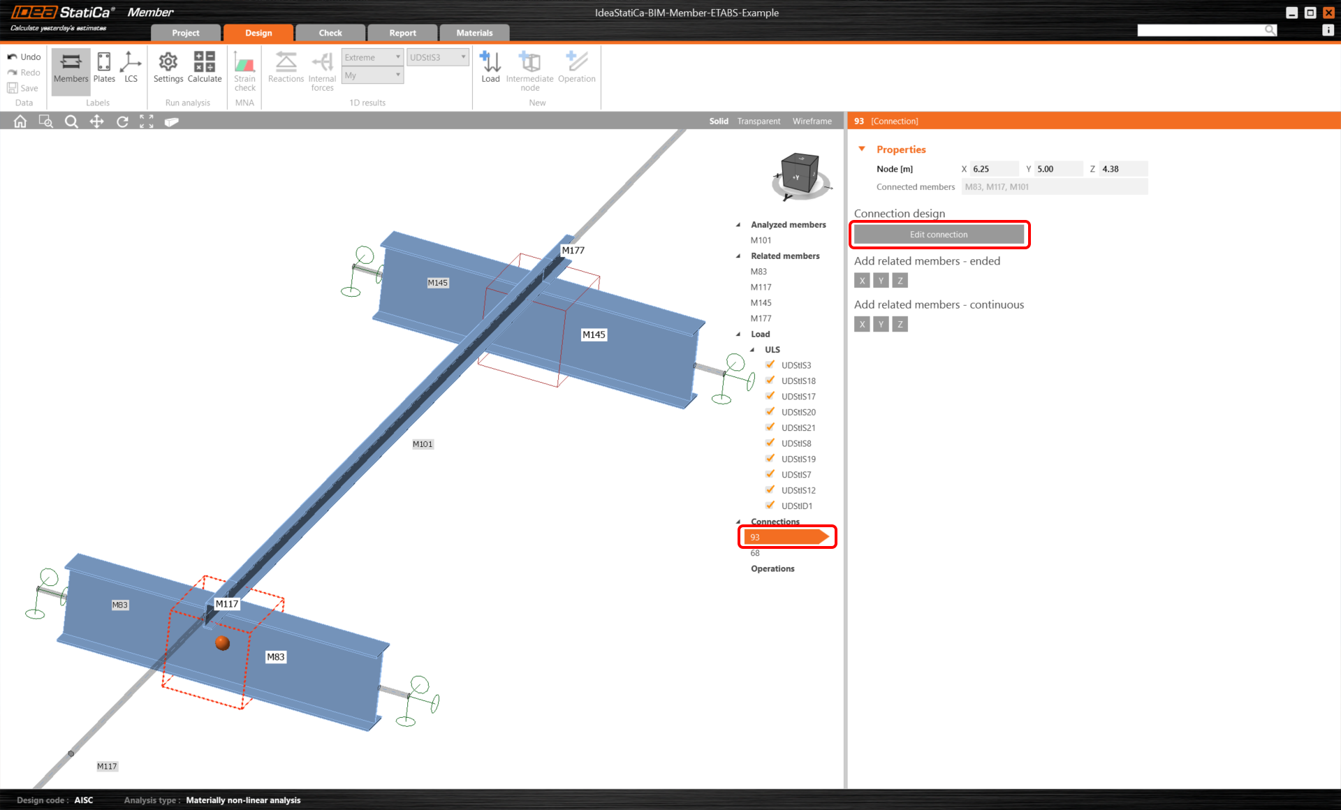
Zunächst bemessen wir die Verbindungen des U-Profil-Bauteils. Wählen Sie daher die erste Verbindung aus und klicken Sie auf Edit connection. Wie Sie sehen können, werden I-Profile nun durch ein durchgehendes Element dargestellt, dank der Zusammenführung, die wir vorgenommen haben.
Verbindungsbemessung
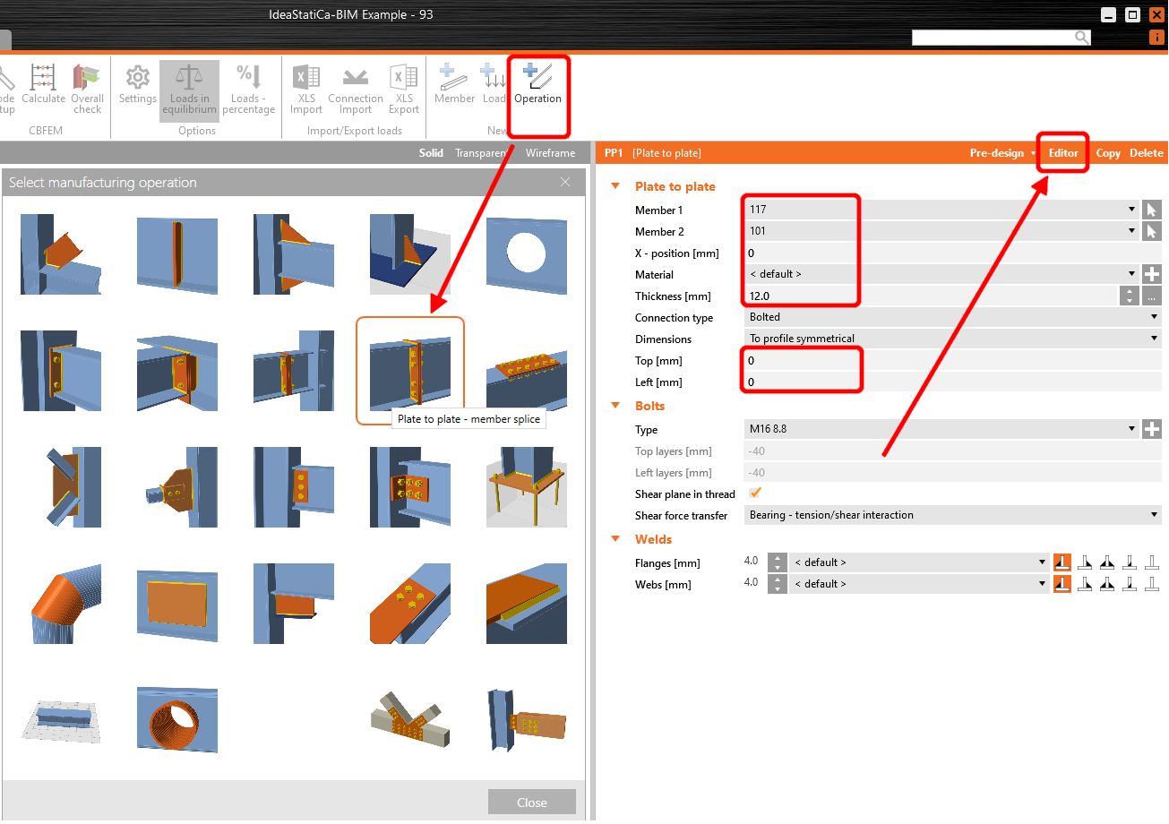
Klicken Sie auf Operation und wählen Sie Plate to plate. Ändern Sie die Werte gemäß der Abbildung und klicken Sie dann auf Editor.
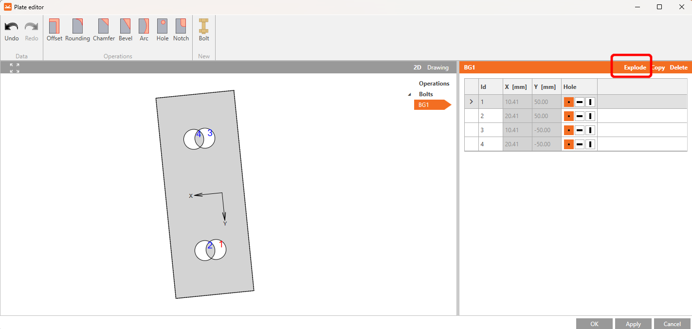
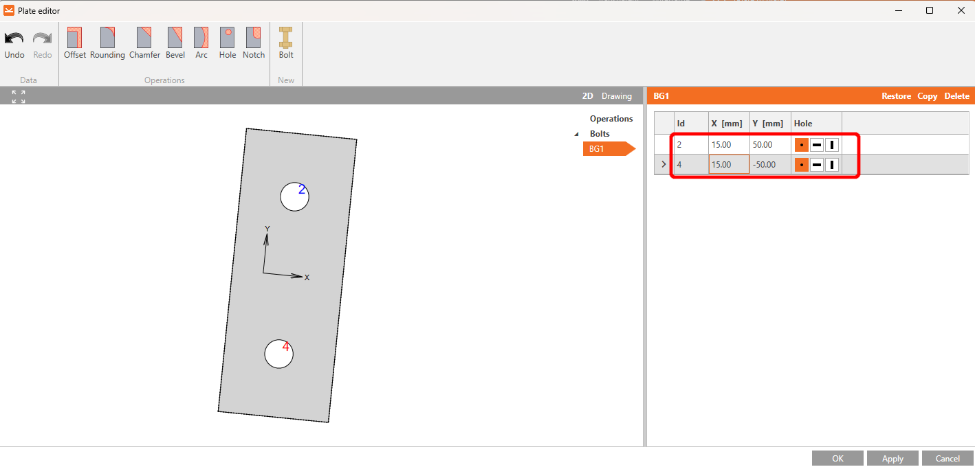
Klicken Sie auf Explode, löschen Sie die Schrauben Nr. 1 und 3, und setzen Sie die Werte für die Schrauben Nr. 2 und 4 gemäß der Abbildung.
Nachdem Sie die Änderungen vorgenommen haben, sollte das Element wie folgt aussehen. Fahren Sie fort, indem Sie auf OK klicken.
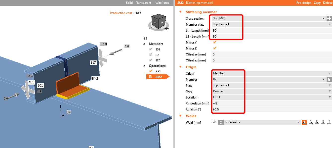
Die nächste Operation ist das Stiffening member. Zunächst müssen Sie einen neuen L80x6-Querschnitt hinzufügen. Klicken Sie auf das weiße Kreuz in der Querschnittszeile, wählen Sie L-Profil und geben Sie den erforderlichen Namen in die Suche ein. Füllen Sie anschließend die Werte wie in der folgenden Abbildung gezeigt aus. Unser Modell sollte danach wie in der Abbildung unten aussehen.
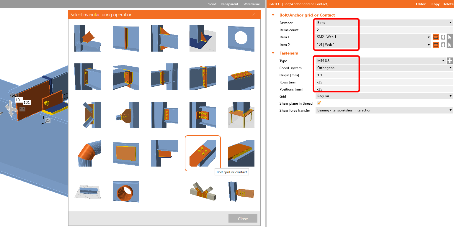
Fügen Sie die Operation Bolt/Anchor grid hinzu.
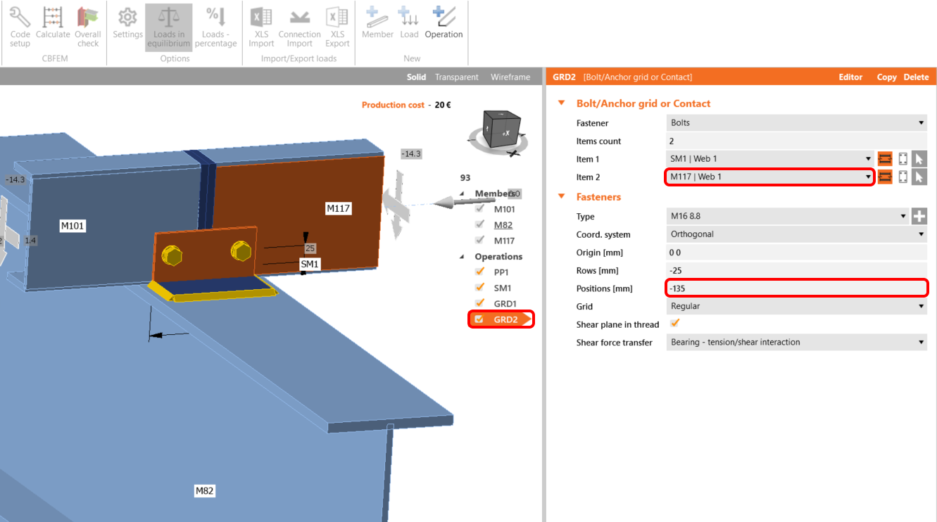
Kopieren Sie diese Operation und ändern Sie die ausgewählten Werte.
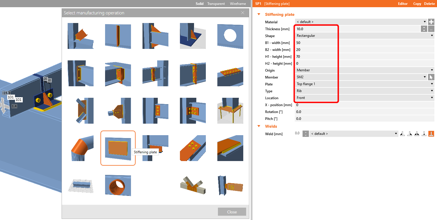
Fügen Sie nun eine Stiffening plate zur Verbindung hinzu und setzen Sie die Werte gemäß der Abbildung.
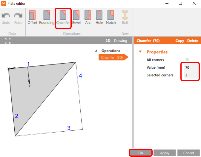
Gehen Sie dann zum Editor, wählen Sie die Fase-Operation und stellen Sie sie gemäß der Abbildung ein.
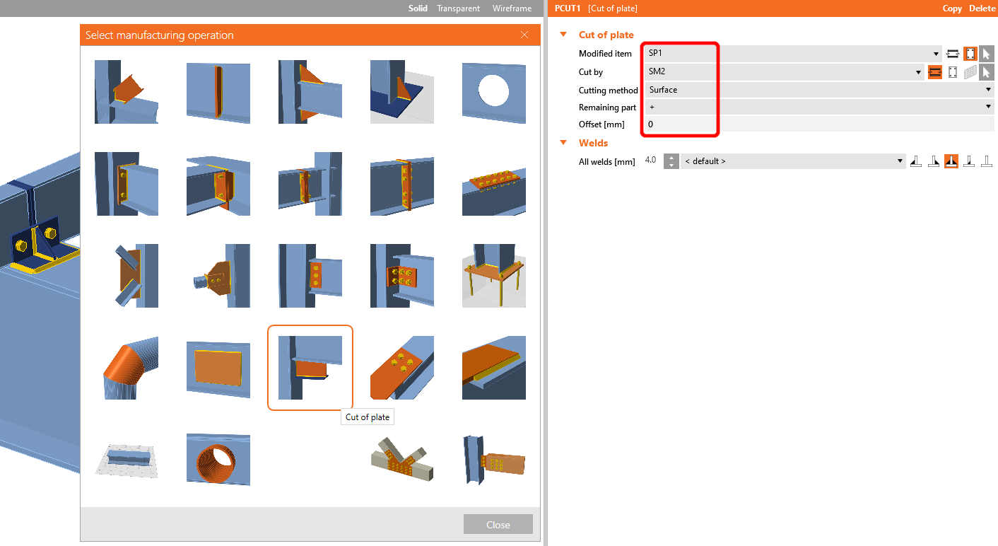
Die letzte Operation ist die Schnitt-Operation für das Blech.
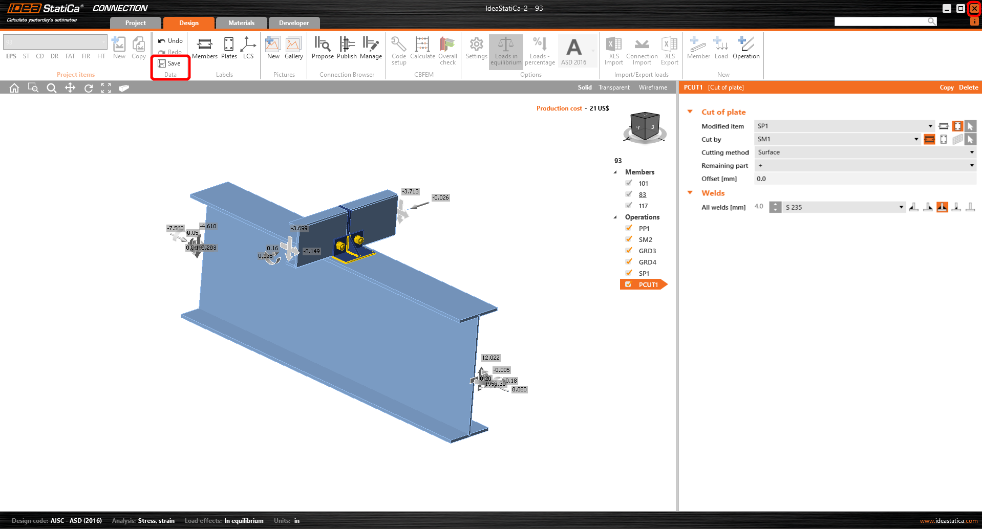
Klicken Sie nun auf Speichern und schließen Sie das Modul Connection.
Prüfen und Steuern
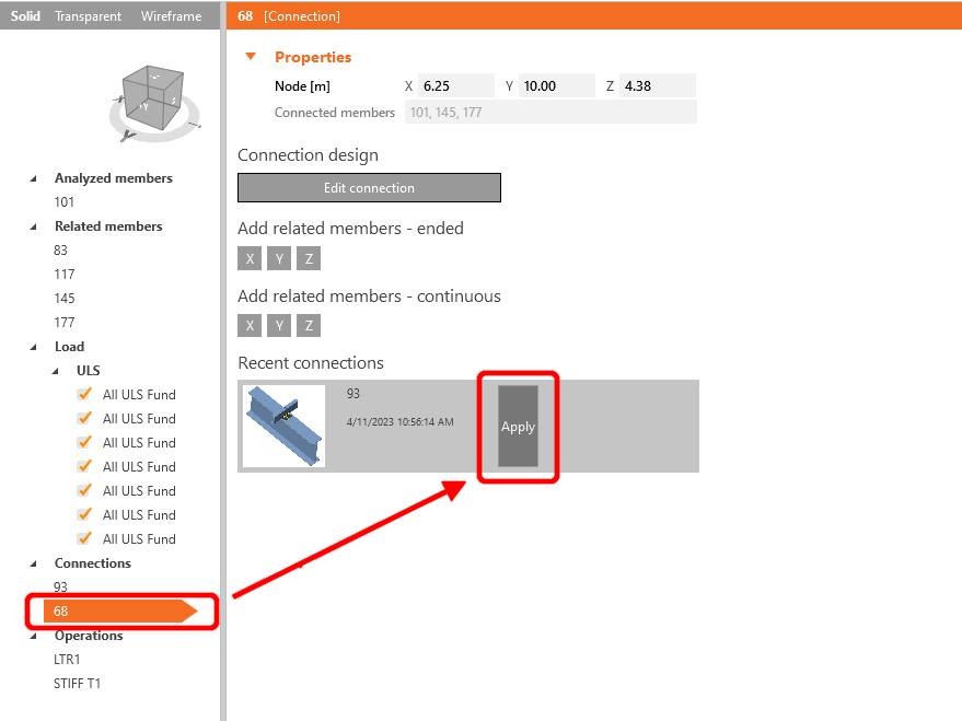
Da wir auf beiden Seiten des Bauteils ähnliche Verbindungen haben, können Sie die Operationen vom ersten Knoten auf einen anderen kopieren, indem Sie auf Übernehmen klicken.
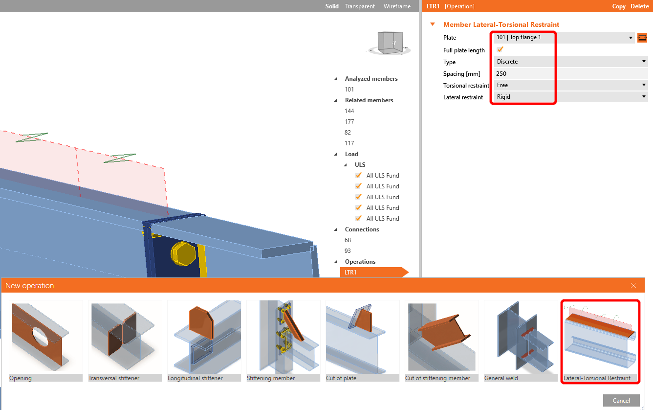
Bevor Sie mit der Analyse beginnen, klicken Sie zunächst mit der linken Maustaste auf das U-Bauteil, fügen Sie die Operation Seitliche Halterung hinzu und legen Sie die Werte gemäß der Abbildung fest.
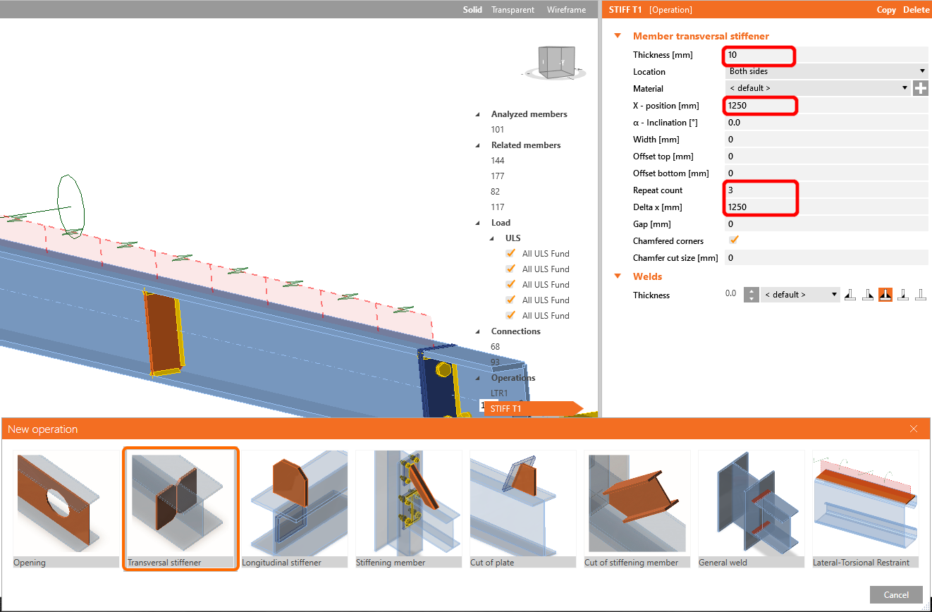
Fügen Sie im nächsten Schritt die Operation Steifen auf dieselbe Weise wie im vorherigen Schritt hinzu und konfigurieren Sie die Werte wie dargestellt.
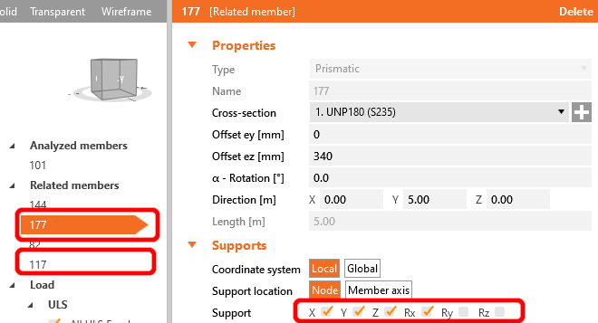
Für das realistische Verhalten der zugehörigen Bauteile schränken Sie die Lager der angeschlossenen Pfetten auf X, Y, Z und Rx ein.
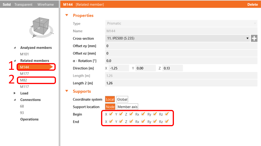
Verfahren Sie ebenso für die I-Profil-Tragwerksbauteile; schränken Sie diese auf X, Y, Z und Rx, Ry, Rz ein.
Das Bauteil ist nun bereit für die Analyse.
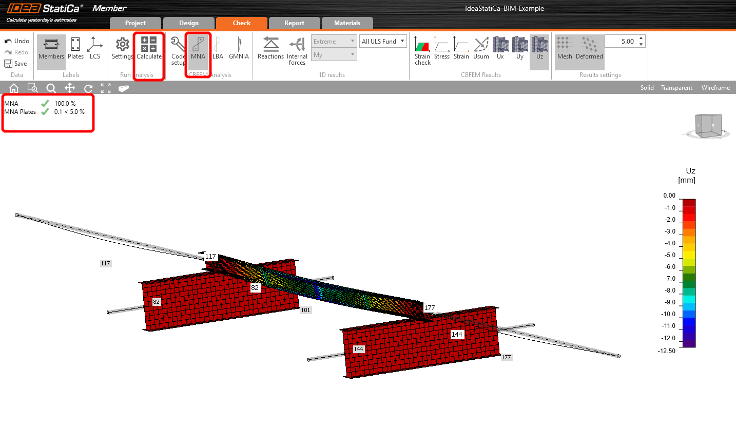
Wählen Sie die Registerkarte Nachweis und führen Sie die MNA-Analyse (materiell nichtlinear) aus.
Die zweite Analyse ist die LBA (Biegedrillknicken-Analyse), bei der wir einen kritischen Faktor von weniger als 15 erhalten.
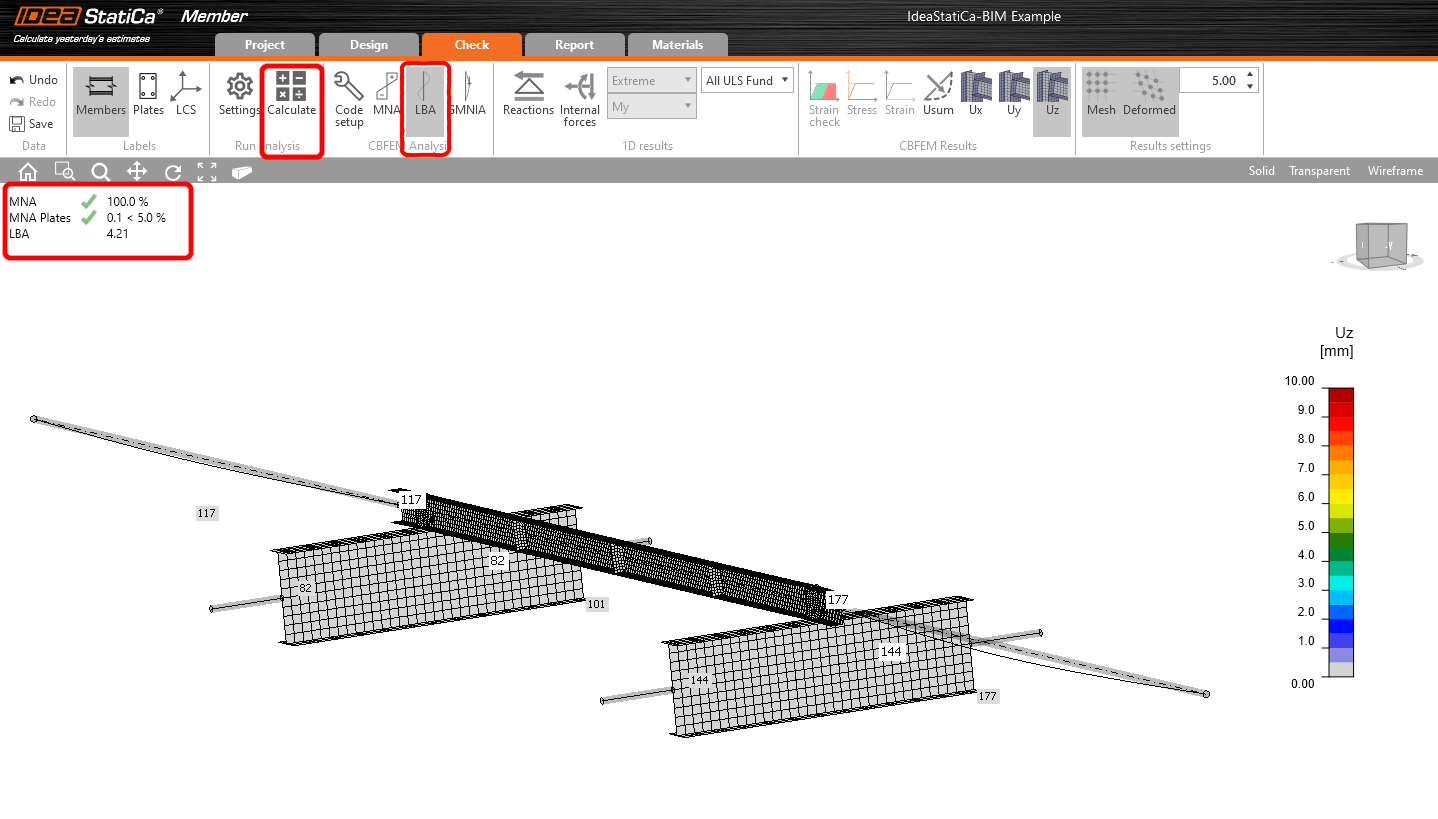
Dieses Ergebnis zeigt die Notwendigkeit, die GMNIA-Analyse (geometrisch und materiell nichtlinear) durchzuführen.
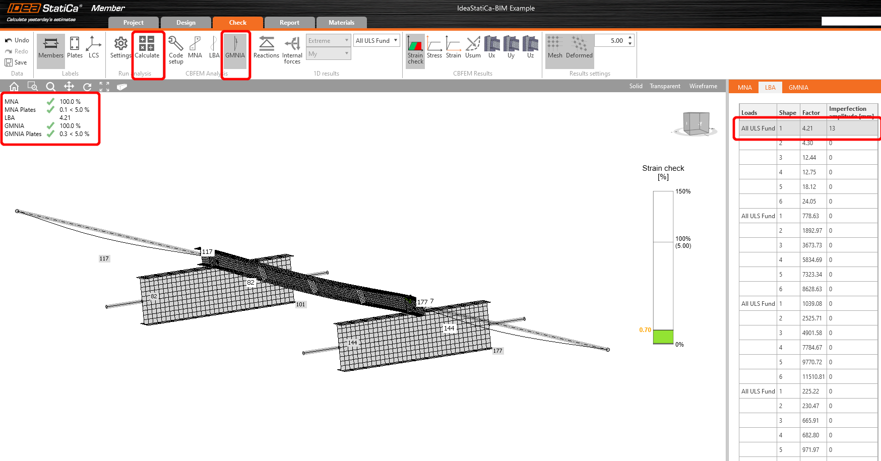
Da Biegedrillknicken untersucht wird, kann der Faktor k0 = 0,5 verwendet werden. Die Amplitude 0,5 • 5000 / 200 = 12,5 mm wird auf die erste Knickform aufgebracht.
Klicken Sie auf das Imperfektion-Feld für den kritischen Knickfaktor und tragen Sie den oben berechneten Wert in die Zeile ein, wie in der folgenden Abbildung dargestellt. Anschließend können Sie die letzte GMNIA-Analyse (geometrisch und materiell nichtlinear) ausführen.
Weitere Informationen:
- Bauteilstabilität in IDEA StatiCa Member.
- Biegedrillknicken
Wir haben erfolgreich eine Pfette aus SAP2000 importiert und überprüft.
Testen Sie IDEA StatiCa kostenlos
Anhänge zum Download
- IdeaStatiCa-BIM-Member-SAP2000-Example.zip (ZIP, 222 kB)
- BIM-Member-SAP2000-Example.sdb (SDB, 51 kB)