When a shear connection transmits a bending moment
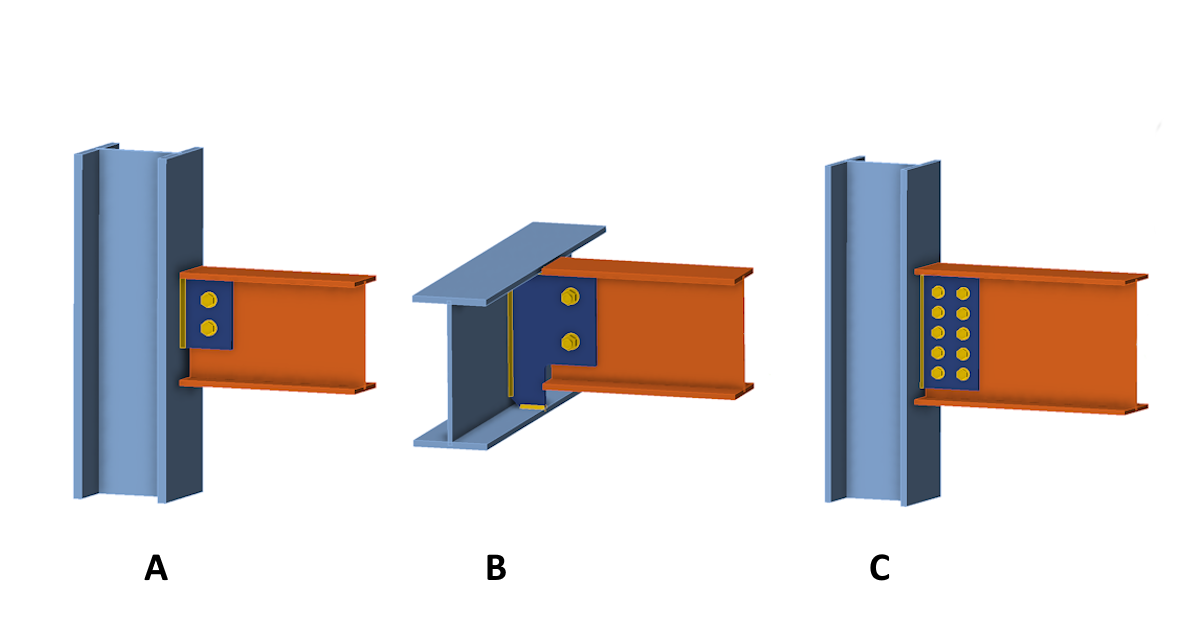
The title picture shows three typical connections of an I-beam by a vertical connection plate (fin plate) to a column or supporting horizontal beam. Also, the term single plate shear connection is used. Each of these connections behaves differently when transferring loads. Let's look at them one by one.
Connection A
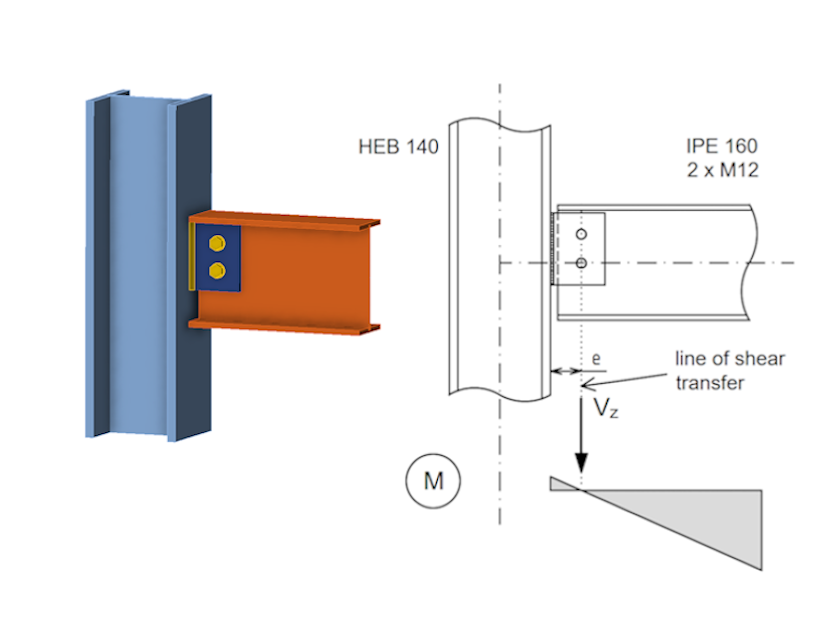
Connection A is a very typical case of simple shear connection in which a horizontal beam is connected to a column by a fin plate with a small number of bolts in one line. Obviously, the rotational stiffness of this connection will be very small. Also, taking into account the tolerances in the bolt holes, it is common in design practice to consider the connection as an pinned connection. The progression of bending moments on the connected element is shown in the figure. There is zero bending moment at the connection point and the bolts transmit only the vertical displacement force Vz. Conversely, the weld connecting the plate to the column is subjected to a displacement force Vz and a bending moment M=Vz·e
In the IDEA StatiCa Connection application, this type of response and loading can be easily modeled by entering only the vertical shear force and setting the load position at the center of the bolts.
Connection B
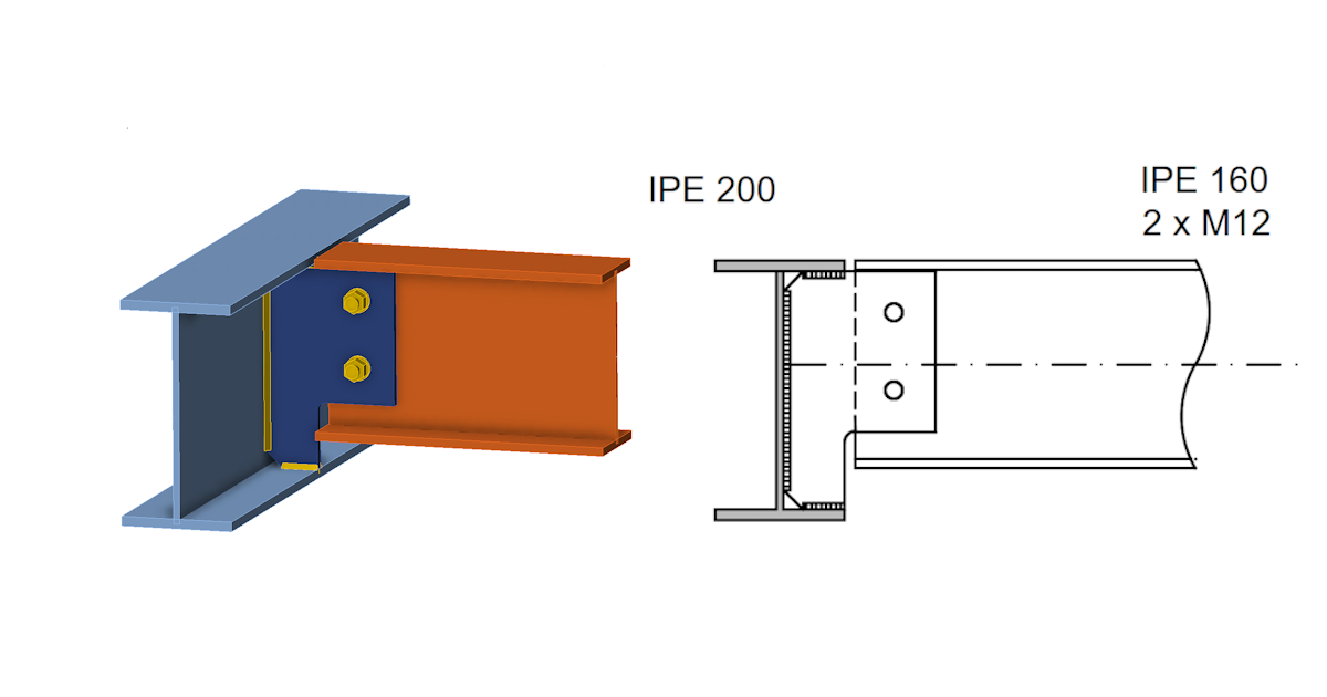
Lets look at second shear connection design example. Connection B is another type of simple shear connection, that is often used in steel structures. In this case, the I-beam is connected to the perpendicular supporting girder with the I-section. Typically, this may be a connection of a ceiling beam to the edge girder. Assume that the ceiling itself does not consist of a rigid floor slab. Plus, the horizontal movements of the top flange of the supporting girder or the twisting of the girder section are not restricted. The girder is supported at the ends against torsion. However, the torsional compliance of the girder causes the response of connection B to be significantly different compared to connection A.
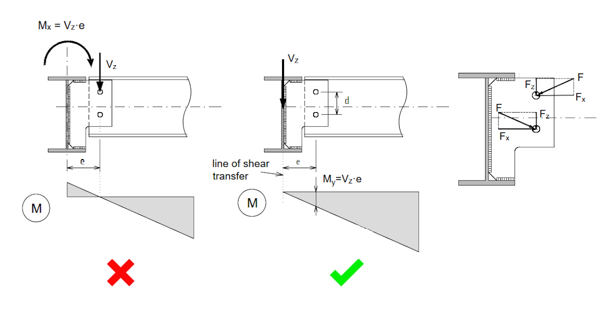
First, let us assume that the response to the load is the same as for connection A. It means that the connection acts as a pin joint with an axis of rotation at the center bolts group. The vertical reaction Vz then acts on the supporting girder with eccentricity e in the same way as for connection A. Torsion moment Mx is thus applied to the girder.
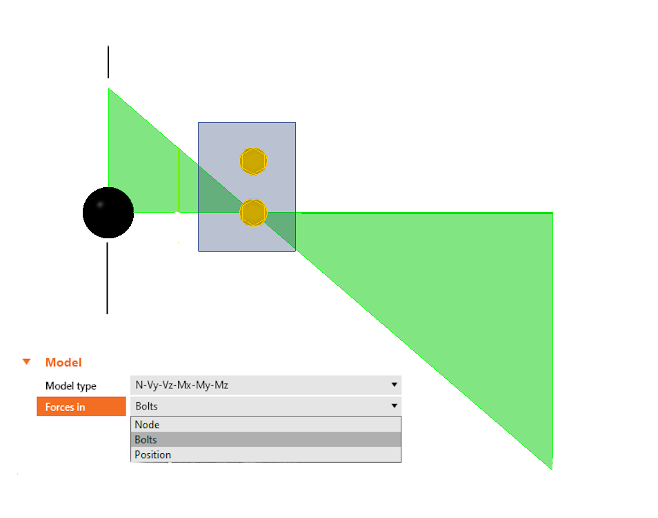
However, due to its very low torsional stiffness, the girder is unable to transfer moment Mx to the supports. On the contrary, a twisting of the girder and a redistribution of the bending moment at the beam and connection will occur. In the limit case of negligible torsional stiffness of the girder, there will be zero moment in the place of the axis of the girder. It is clear that the bolted shear connection is then loaded by a bending moment M=Vz·e. This is distributed, in our case, into a force pair Fx= M/d. The resulting force F acting on the bolt is the vector sum of the vertical component Fz=Vz/2 and the horizontal component Fx. The bending moment in the shear connection (!) thereby has a decisive influence on the dimension of the connection. The example below will show how large the influence of the bending moment can be.
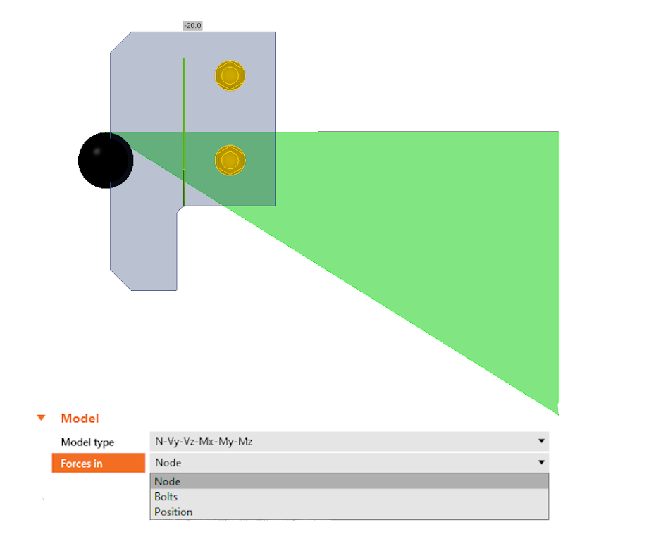
In the Connection application, this type of response and loading can be easily modeled by entering only the vertical shear force and setting the load position at the node.
As already mentioned, the response of the connection described and schematically visualized above refers to a situation where the girder has very low torsional stiffness. However, if the torsional stiffness of the girder is not negligible, the result will be a negative bending moment over the axis of the girder. Plus, the response of the connection and the moment curve will shift towards connection A.
When will this occur? Obviously when a torsionally rigid section of the girder is used. But also for connections close to the ends of the girder, which is otherwise torsionally weak. This is because the girder is supported for torsion at the ends and the ability of the cross-section to twist is limited near the supports. In other words, on a girder that supports a series of parallel beams, we can have shear connections that correspond in behavior to both type A (near the supports) and type B (midspan of the girder). It is then conservative and safe to design the connection plate and bolts to envelope the stresses of type A (less bolt stress and higher load on the weld connection of the fin plate to the girder), and type B (higher bolt stress and less load on the weld connection of the fin plate).
Connection C
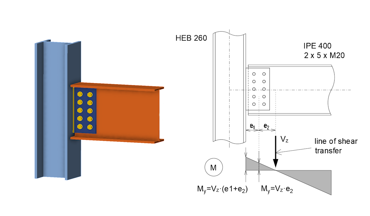
Let's look at the "large" single palate shear connection of the I-beam to the column – connection C. For example, consider five bolts in two columns in the fin plate. Obviously, this connection may already have a considerable rotational stiffness, which will affect the distribution of internal forces. The position of the zero bending moment will shift towards the midspan of the connected beam and a negative bending moment M=Vz.e2 will be applied at the center of the bolts group. The magnitude of the moment (or the magnitude of the eccentricity e2) will depend on the rotational stiffness of the bolted connection. This can be easily determined using the Connection application and then the calculated stiffness of the connection can be categorized according to the design code.
If the connection is categorized as pinned and has sufficient rotational capacity, the simplification of the small bending moment transmitted by the connection can be neglected. The distribution of internal forces in the connection can then be considered in the same way as for a type A connection. If the engineer decides to design the connection without this simplification, or if the connection is classified as semi-rigid, the calculated rotational stiffness of the connection must be included in the global analysis model. The bending moment in the connection is calculated then and the connection is checked for shear and moment using the Connection app.
Analysis with IDEA StatiCa Member
One may argue that the described behavior of shear connections is only a hypothesis and it would be good to support it by calculation. Therefore, we will now verify the presented behavior of the connections using the IDEA StatiCa Member application. IDEAStatiCa Member allows us to model the behavior of steel structures, or their parts, very accurately. The individual members, beams, and columns are modeled in 3D using shell elements. The connections between the elements are modeled using a Component-based Finite Element Method (CBFEM) model.
This means that the individual components of the connection (bolts, connection plates, welds, etc.) are directly included in the 3D computational model. The stiffness distribution and spatial behavior of the structure are thus realistically represented in the mathematical model. The application allows us to display internal forces in individual members, which are then calculated by backward integration of the stresses from the shell elements. Let's compare the bending moment diagrams at the connections calculated by the Member app with the diagrams presented above for individual connections.
Connection A analyzed by Member
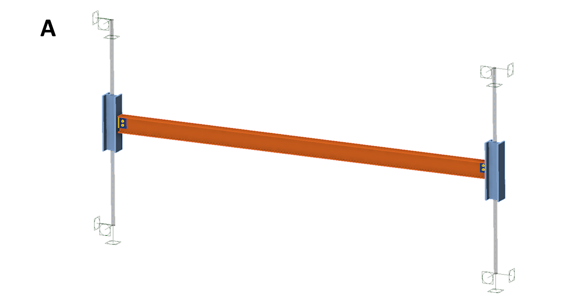
First, let's look at connection A. The picture above shows a simple structure consisting of a pair of columns made of an HEB140 section. A beam made of an IPE160 section is connected to the columns by connection A. The length of the beam is 4 m and the load is 10 kN/m. The bending moment diagram is shown in the following figure. It can be seen that there is almost zero bending moment at the bolted connection point and the moment shape corresponds very well to what was presented in the analysis of connection A's response.
Connection B analyzed by Member
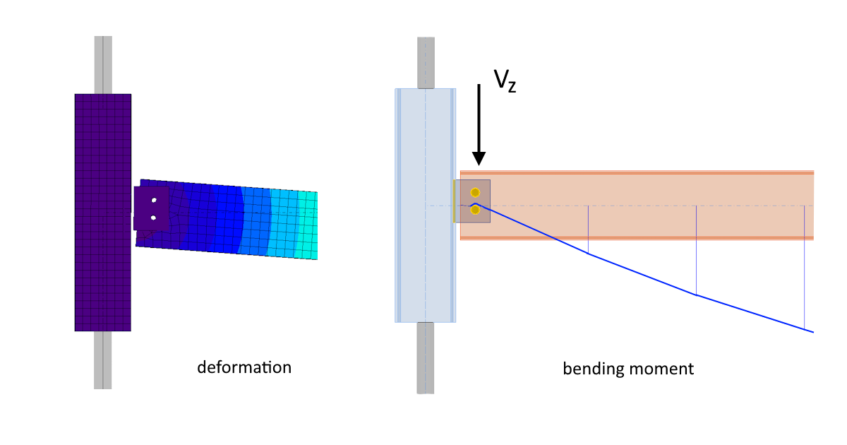
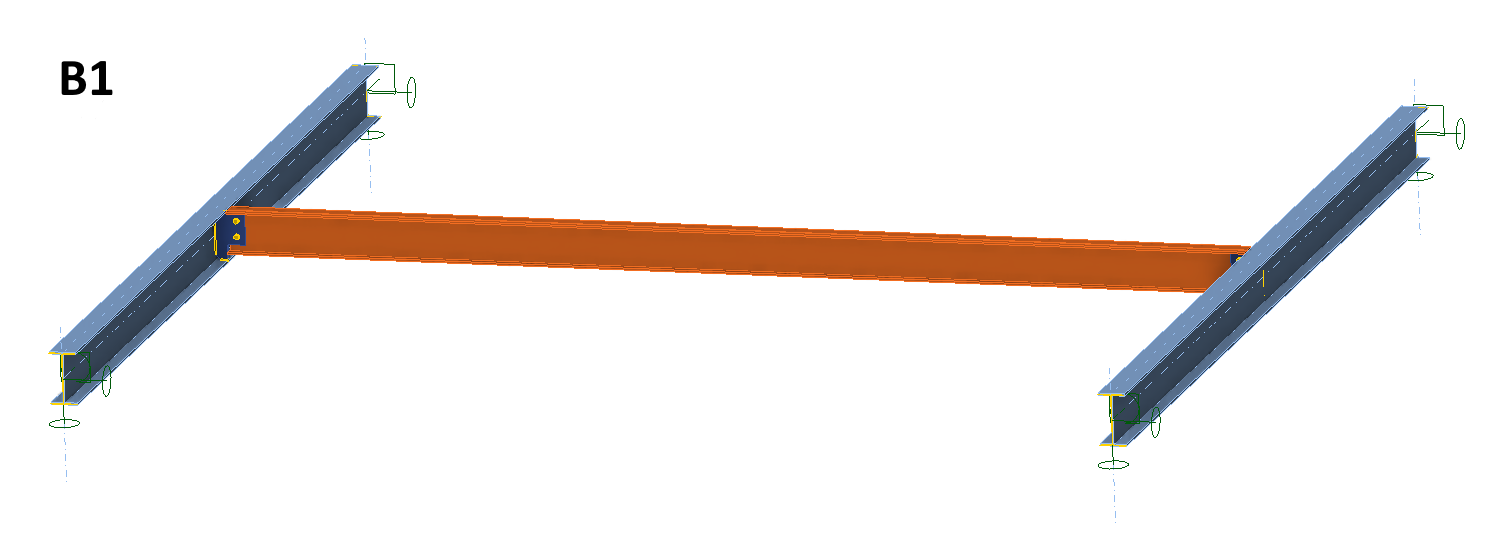
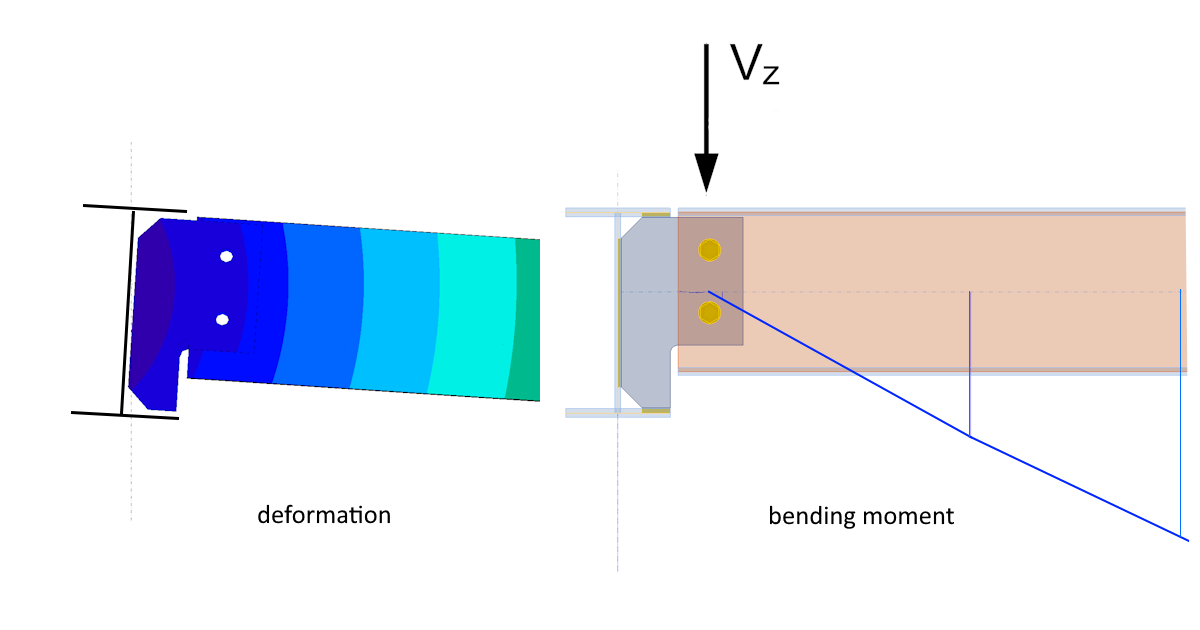
Let's verify the response of connection B on a simple structure consisting of a pair of IPE200 girders of four meters in length. The flanges are pin-connected at the ends for bending and are rotationally fixed. A beam made of an IPE160 section is bolt-connected between the four-meter-spaced girders by connection B. The load is again 10 kN/m. The integration of the internal forces is done only for the individual beams and from the elements that model them. Therefore, the bending moments on the beam are not displayed up to the axis of the girder and the extrapolated moment curve is represented with a dashed line. It is clear that there is a positive bending moment at the position of the bolts and extrapolated the moment curve has a near-zero value at the wall of the girder. Therefore, the moment diagram and the point vertical force Vz transfer again correspond very well to what was presented in the analysis of the response of the type B connection.
And what are the forces in the individual bolts in the connection? The shear force in one bolt from the vertical shear force in the beam is 10 kN. The total shear force in one bolt (from the vertical shear force and moment in the connection) is, in our case, 31 kN. This is a three-times-higher value compared to the response of the type A connection. Of course, this is not universally true, it depends on the dimensions of the beams, the distance of the bolts from the girder wall, etc. However, it can be seen that designing a type B connection and neglecting the moment in it could be a big mistake.
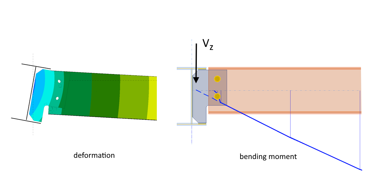
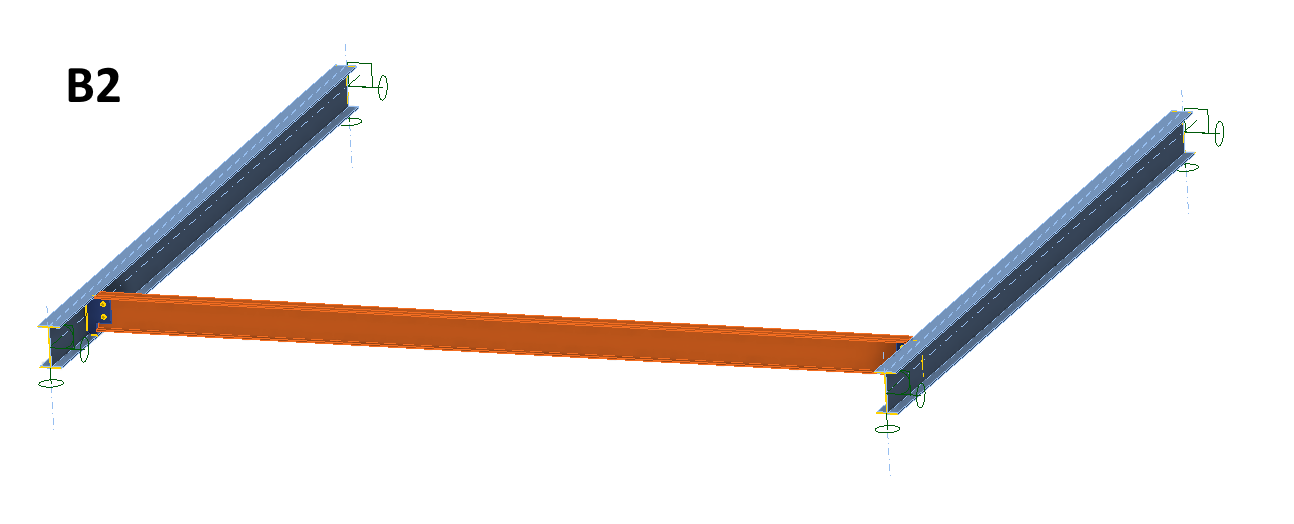
Let's look at the situation discussed earlier, where the connected I-beam is moved to a distance of 0.5 m from the support.
According to the earlier analysis, the bending moment should be changed because the capacity of the girder to twist is limited at the supports. Plus, the forces' distribution should be close to the response of the type A connection. It is clear from the moment diagram from the Member app that this is indeed the case. In this instance, the zero moment is almost at the center of the bolts group and the bolts are loaded by the vertical shear force.
Connection C analyzed by Member
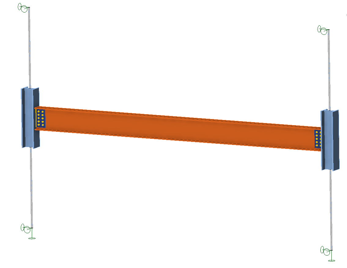
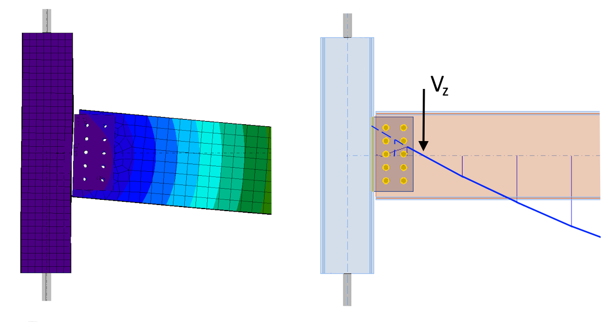
But what about the connection C analyzed by the Member application? We will again use a simple construction consisting of a pair of columns made of HEB240 profiles and a beam made of an IPE400 profile, which is connected to the columns using the C-type shear connection. The length of the beam is 6 m, and the load is 80 kN/m.
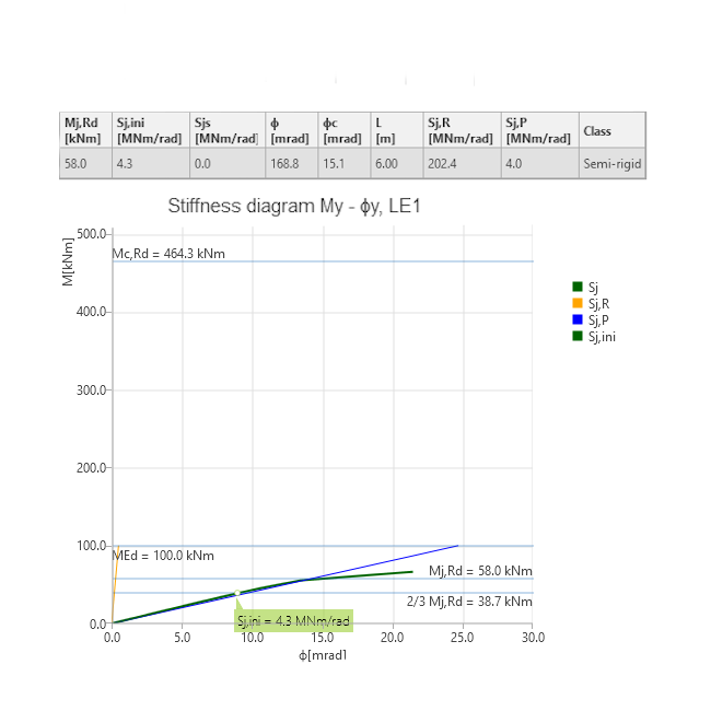
The bending moment diagram is shown in the following figure. It can be seen that there is a negative bending moment at the center of the bolt group (again illustrated by extrapolating the moment on the beam). The connection thus behaves as a semi-rigid one. This is also confirmed by the stiffness analysis and categorization of the connection in the Connection app.
Conclusion
Shear connections in steel structures are relatively simple structural elements, and seem relatively easy to design. But as can be seen, the behavior of the same type of single plate shear connection can vary significantly depending on where in the structure it is used. With the IDEA StatiCa Connection and Member applications, you can analyze the real behavior of the connection in the structure and obtain safe results in accordance with the applicable codes.
Try IDEA StatiCa for free