Poziția forței de forfecare - introducere și vizualizare
A fost implementată o opțiune pentru setarea poziției forței de forfecare într-o îmbinare, pentru a asigura o modelare mai fluidă. În plus, puteți vedea imediat diagrama momentului încovoietor datorat forței de forfecare unitare!
Să analizăm funcționalitățile una câte una.
Poziția forței de forfecare la fața elementului
În multe cazuri, poziția forței de forfecare este considerată la fața elementului. Vă puteți confrunta cu această situație la proiectarea unei îmbinări cu, de exemplu, un cornier de prindere, o placă de capăt scurtă, un reazem flexibil etc. Am dezvoltat o modalitate de introducere a poziției forței de forfecare, astfel încât să deveniți mai eficienți și să scăpați de munca repetitivă și obositoare.
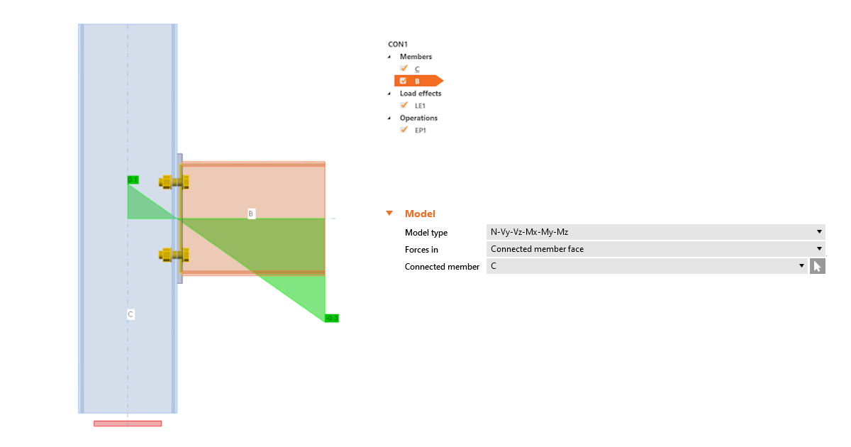
Puteți seta poziția folosind funcționalitatea Fața elementului conectat. Software-ul o va seta automat în funcție de suprafața elementului conectat. Aceasta înseamnă că nu mai este necesară ajustarea manuală prin coordonate. Iar odată cu schimbarea secțiunilor transversale, poziția este în continuare păstrată.
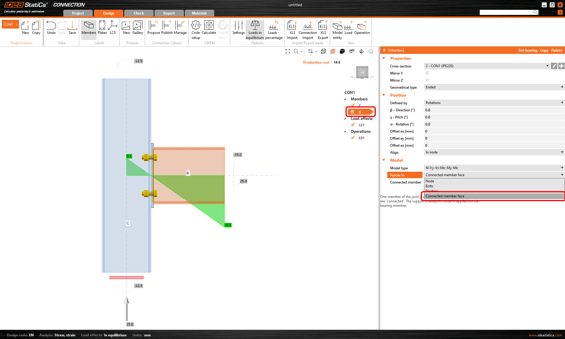
Cum funcționează? Selectați pur și simplu elementul pentru care doriți să setați poziția forței și selectați opțiunea Fața elementului conectat din secțiunea Forțe, sub Model, în fila de proprietăți. Se recomandă să selectați întotdeauna manual elementul conectat.
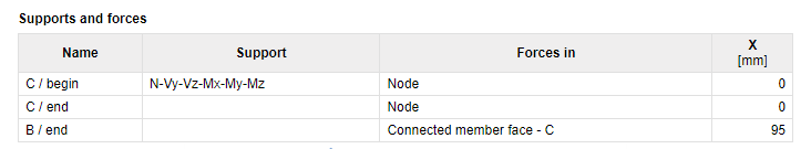
Metoda și poziția sunt afișate și în raport.
O modalitate îmbunătățită de vizualizare a poziției forței de forfecare
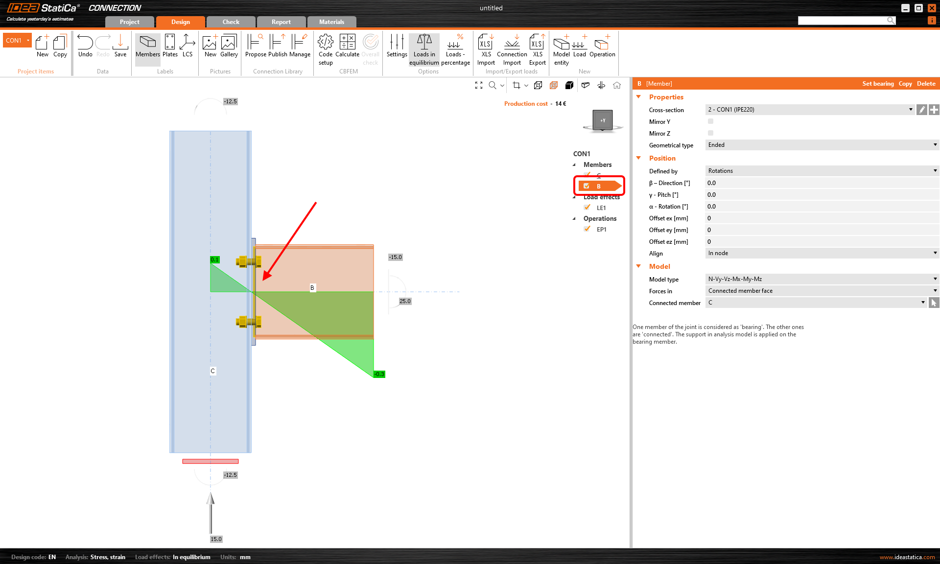
Aplicația Connection afișează acum valoarea momentului încovoietor din forța de forfecare unitară Vz=-1 pentru fiecare îmbinare modelată. Unitatea este conform setărilor de unități (de ex., Vz= -1 kN sau -1 kip). Momentul încovoietor respectă, de asemenea, setările de unități (de ex., kNm sau kip-ft).
Diagrama poate fi afișată în modul de vizualizare Transparent sau Wireframe, adică selectați elementul pentru care doriți să vedeți diagrama și utilizați unul dintre aceste moduri.
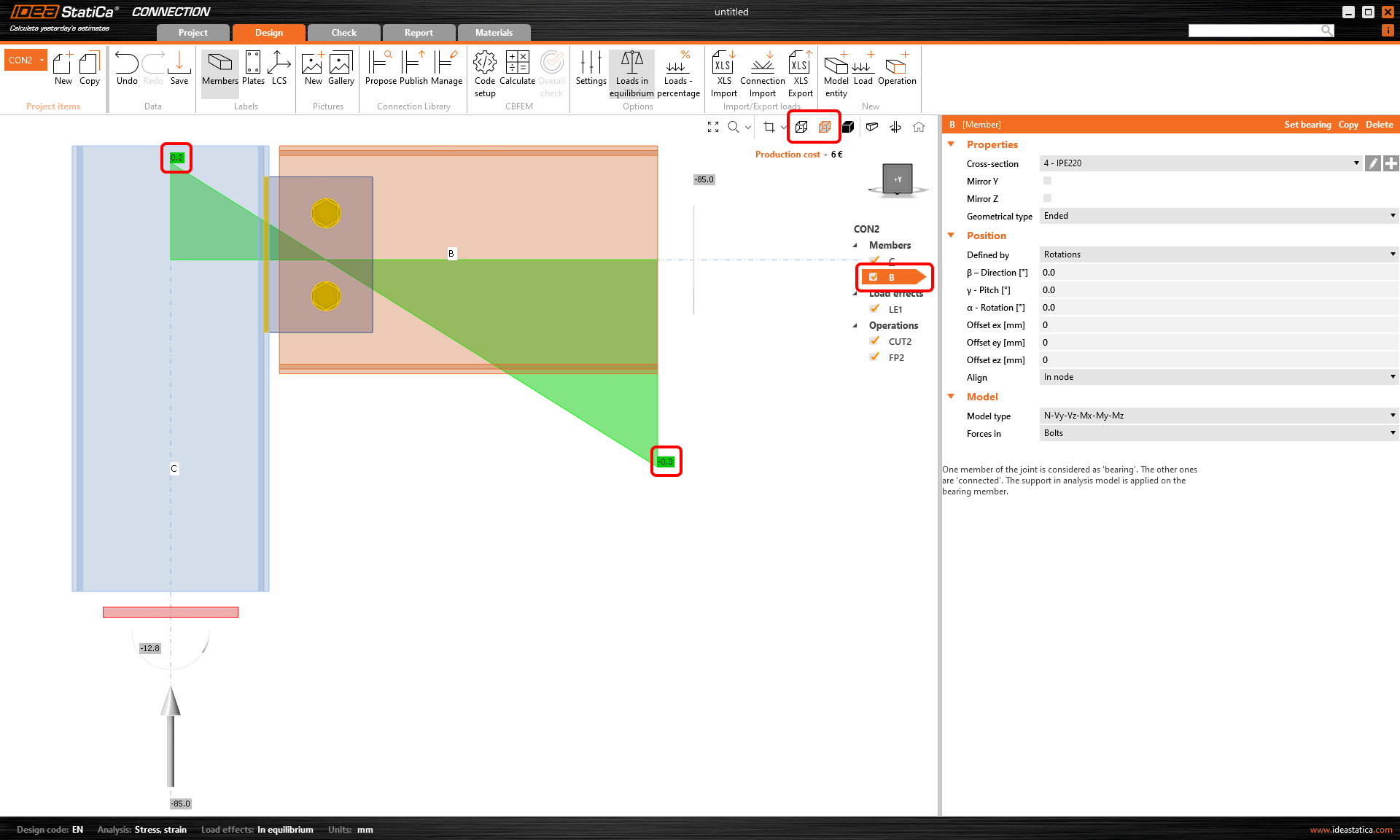
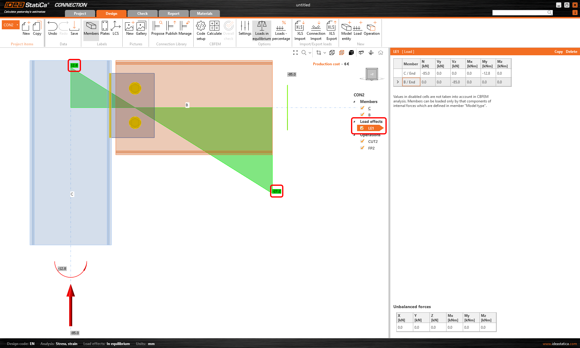
Diagrama reală a momentului încovoietor folosind încărcările introduse este în continuare afișată în secțiunea Efecte ale încărcărilor.
Disponibil în edițiile IDEA StatiCa Steel și IDEA StatiCa Complete.