Durata de viață la oboseală prin metoda tensiunii nominale
1. General
1.1. Metoda tensiunii nominale
Durata de viață de calcul este estimată prin metoda tensiunii nominale, conform EN 1993-1-9: 2005, astfel:
\[\Delta \sigma_{E,2}=\sigma_{max}-\sigma_{min}\]
\[\Delta \sigma_R=\gamma_{F1} \sigma_{E,2}\]
\[N_R=N_c\sigma_c^m / \Delta \sigma_R^m\]
unde:
- \(\sigma_{max},\,\sigma_{min}\) – valorile extreme ale tensiunii
- \(\Delta \sigma_{E,2}\) – valoarea caracteristică a domeniului tensiunii nominale
- \(\gamma_{F1}\) – factor parțial de siguranță, pentru aceste calcule \(\gamma_{F1}=1.15\)
- \(\Delta \sigma_R\) – valoarea de calcul a domeniului tensiunii nominale
- \(N_c\) – rezistența de referință la oboseală, pentru toate calculele \(N_c=2\cdot 10^6\)
- \(\sigma_c\) – valoarea de referință a rezistenței la oboseală preluată din Tab. 8.1–8.10 din EN 1993-1-9:2005
- \(m\) – panta curbei de rezistență la oboseală, pentru toate calculele \(m=3\)
1.2. Tensiunea din modelul analitic
Tensiunea calculată din combinația de încărcări se obține prin:
\[\sigma_i=F_i/A\]
unde:
- \(F_i\) – valoarea extremă a forței axiale
- \(A\) – aria secțiunii transversale a unei plăci
1.3. Modelul numeric
Modelele MEF sunt pregătite în Ansys 19.1 utilizând elementul solid nr. 181. Dimensiunea plasei este \(0.4t \times 0.4t\). Modelele CBFEM sunt realizate în IDEA StatiCa versiunea 22.1 cu elemente de tip placă cu patru noduri. Se utilizează setările implicite ale plasei, dimensiunea minimă a plasei este de 10 mm, iar cea maximă de 50 mm.
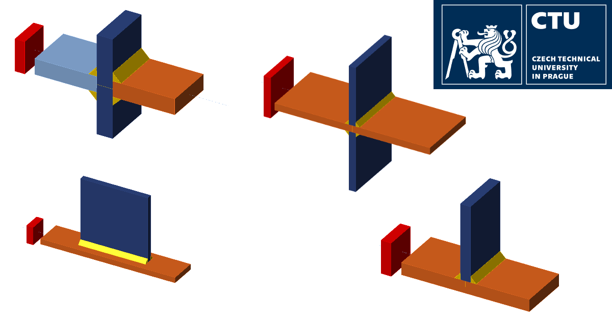
2. Îmbinare cruciformă cu sudură de colț transversală
2.1. Descriere
O îmbinare cruciformă sudată din trei plăci este realizată prin suduri de colț cu grosimea de gât de 6 mm. Dimensiunile plăcilor sunt 50x16 mm, din oțel S450; vezi Fig. 1. Îmbinarea este încărcată cu forță de întindere.
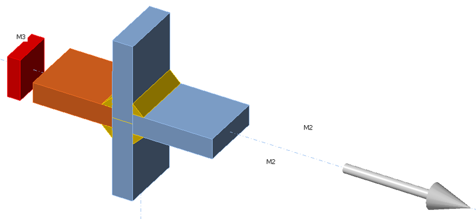
Fig. 1: Îmbinare cruciformă sudată
Această îmbinare corespunde, conform Tab. 8.5 din EN 1993-1-9:2005, detaliului de construcție 1. Categoria de detaliu pentru \(l=\textrm{grosimea plăcii}+2\times \textrm{grosimea sudurii}= 28\, \textrm{mm}\), adică \(l<50\,\textrm{mm}\), este 80.
2.2. Modelul analitic
Pentru această îmbinare, aria secțiunii transversale a plăcii este \(A=50\cdot 16=800\, \textrm{mm}^2\). Rezultatele modelului analitic sunt prezentate în Tab. 1.
Tab. 1: Rezultatele soluției analitice AM
| \(F_{max}\) | \(F_{min}\) | \(\sigma_{max}\) | \(\sigma_{min}\) | \(\Delta \sigma_{E,2}\) | \(\Delta \sigma_R\) | \(N_R\) |
| [kN] | [kN] | [MPa] | [MPa] | [MPa] | [MPa] | [-] |
| 85.3 | 8.53 | 106.7 | 10.7 | 96 | 110.4 | 7.61E+05 |
| 105.8 | 10.58 | 132.2 | 13.2 | 119 | 136.9 | 4E+05 |
| 127.1 | 12.71 | 158.9 | 15.9 | 143 | 164.5 | 2.3E+05 |
| 148.4 | 14.84 | 185.6 | 18.6 | 167 | 192.1 | 1.45E+05 |
| 169.8 | 17 | 212.2 | 21.2 | 191 | 219.7 | 9.66E+04 |
2.3. Modele numerice
Secțiunile de oboseală sunt create utilizând secțiuni de sudură la o distanță față de marginea sudurii pentru a evita influența tensiunii de vârf din geometria locală a sudurii (\(4t=64 \, \textrm{mm} \ge \textrm{lățime} = 50\, \textrm{mm}\)). Rezultatele soluției numerice utilizând MEF și CBFEM sunt prezentate în Tab. 2 și 3.
Tab. 2. Rezultatele soluției numerice – MEF
| \(F_{max}\) | \(F_{min}\) | \(\sigma_{max}\) | \(\sigma_{min}\) | \(\Delta \sigma_{E,2}\) | \(\Delta \sigma_R\) | \(N_R\) |
| [kN] | [kN] | [MPa] | [MPa] | [MPa] | [MPa] | [-] |
| 85.3 | 8.53 | 106.8 | 10.7 | 96.1 | 110.6 | 7.58E+05 |
| 105.8 | 10.58 | 132.6 | 13.3 | 119.3 | 137.2 | 3.96E+05 |
| 127.1 | 12.71 | 159.3 | 15.9 | 143.4 | 164.9 | 2.28E+05 |
| 148.4 | 14.84 | 185.5 | 18.6 | 166.9 | 192 | 1.45E+05 |
| 169.8 | 17 | 212.1 | 21.2 | 190.9 | 219.6 | 9.67E+04 |
Tab. 3. Rezultatele soluției numerice – CBFEM
| \(F_{max}\) | \(F_{min}\) | \(\sigma_{max}\) | \(\sigma_{min}\) | \(\Delta \sigma_{E,2}\) | \(\Delta \sigma_R\) | \(N_R\) |
| [kN] | [kN] | [MPa] | [MPa] | [MPa] | [MPa] | [-] |
| 85.3 | 8.53 | 108.7 | 10.9 | 97.8 | 112.5 | 7.2E+05 |
| 105.8 | 10.58 | 134.7 | 13.5 | 121.2 | 139.4 | 3.78E+05 |
| 127.1 | 12.71 | 161.9 | 16.2 | 145.7 | 167.6 | 2.18E+05 |
| 148.4 | 14.84 | 189.1 | 18.9 | 170.2 | 195.7 | 1.37E+05 |
| 169.8 | 17 | 216 | 21.6 | 194.4 | 223.6 | 9.16E+04 |
2.4. Verificare
Calculul numeric CBFEM este verificat pe modele analitice și numerice MEF în funcție de domeniul tensiunii și rezistența la oboseală; vezi Fig. 2. Valoarea medie a diferenței domeniilor de tensiune este de aproximativ 2%.
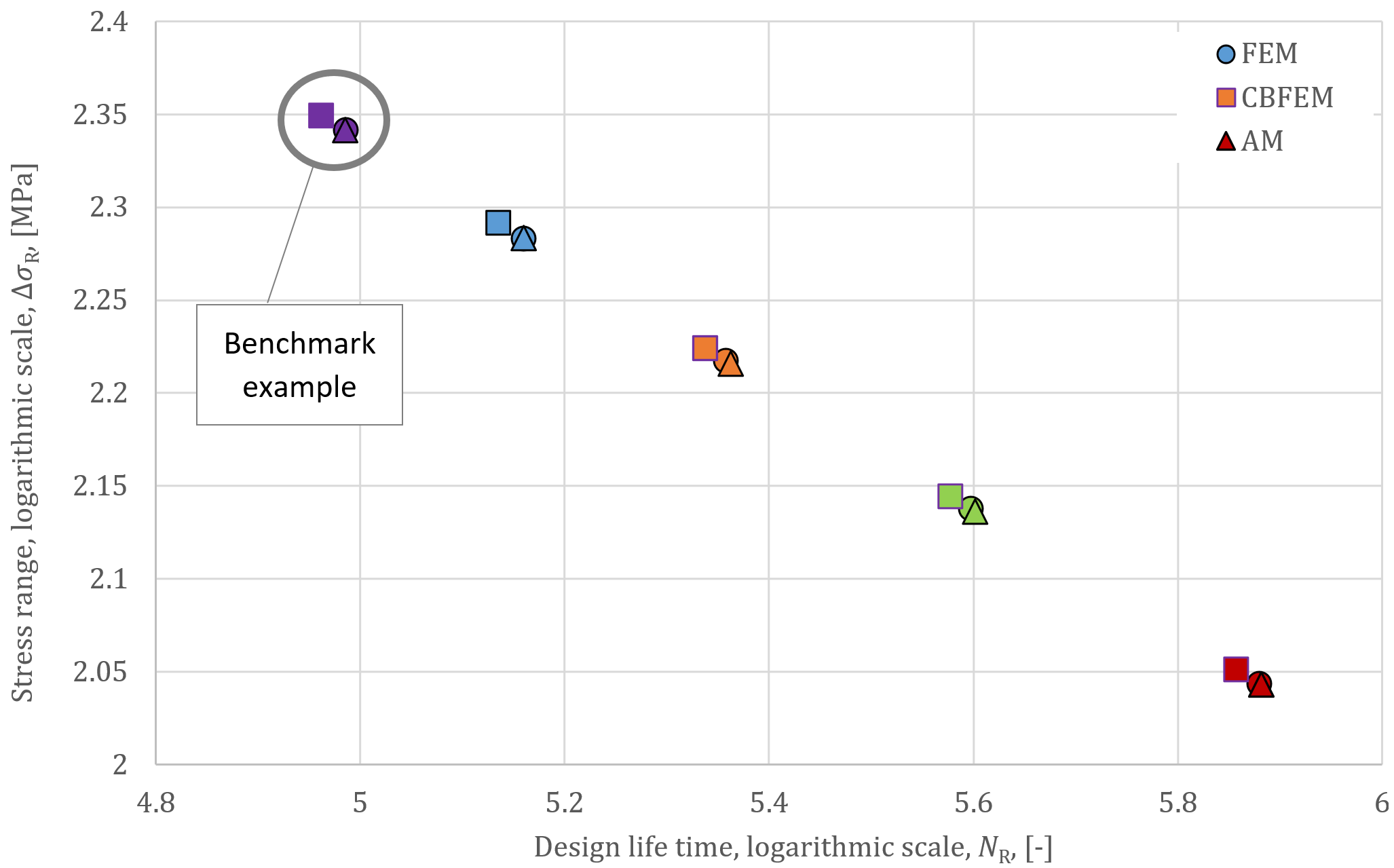
Fig. 2: Comparație a valorilor duratei de viață de calcul NR
2.5. Exemplu de referință
Date de intrare
Plăci:
- Oțel S450
- Placă 50 × 16 mm
Sudură:
- Grosimea de gât = 6 mm
Efecte ale încărcărilor:
- \(F_{min}= 8.53\textrm{ kN}\)
- \(F_{max}= 85.33\textrm{ kN}\)
Rezultate
- Tensiunea normală minimă: \(\sigma_{min}= 10.9\textrm{ MPa}\)
- Tensiunea normală maximă: \(\sigma_{max}= 108.7\textrm{ MPa}\)
- Valoarea caracteristică a domeniului tensiunii nominale: \(\Delta \sigma_{E,2}= 97.8\textrm{ MPa}\)
- Valoarea de calcul a domeniului tensiunii nominale: \(\Delta \sigma_{R}= 112.5\textrm{ MPa}\)
- Valoarea de referință a rezistenței la oboseală: \(\sigma_c= 80\textrm{ MPa}\)
- Panta curbei de rezistență la oboseală: \(m=3\)
- Durata de viață de calcul \(N_R=7.2\cdot 10^5\)
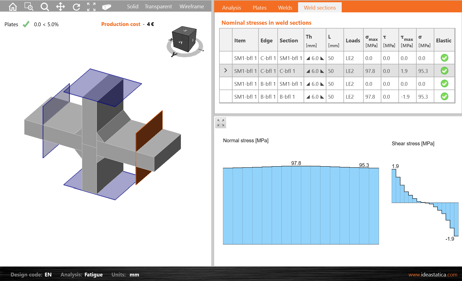
Fig. 3: Valoarea caracteristică a domeniului tensiunii nominale
3. Îmbinare cruciformă a unei plăci cu două plăci transversale
3.1. Descriere
O îmbinare cruciformă sudată cu două plăci transversale este realizată prin suduri de colț cu grosimea de gât de 4 mm; vezi Fig. 4. Dimensiunile plăcilor sunt 90x10 mm. Acestea sunt din oțel S235. Îmbinarea este încărcată cu forță de întindere.
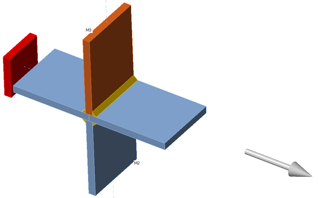
Fig. 4: Îmbinare cruciformă sudată cu două plăci transversale
Conform EN 1993-1-9: 2005, această îmbinare este detaliul de construcție 6 din Tabelul 8.4. Categoria sa de detaliu este 80, deoarece \(l=\textrm{grosimea plăcii}+2\times \textrm{grosimea sudurii}= 18\, \textrm{mm}\), adică \(l<50\,\textrm{mm}\).
3.2. Modele analitice și numerice
Aria secțiunii transversale a plăcii, pentru acest calcul analitic, este A = 900 mm2. Secțiunile de oboseală sunt create utilizând secțiuni de sudură la o distanță față de marginea sudurii pentru a evita influența tensiunii de vârf din geometria locală a sudurii \( (9t = 90\textrm{ mm} \ge \textrm{lățime}=90\textrm{ mm}) \). Rezultatele modelului analitic AM, modelului solid MEF și modelului de placă CBFEM sunt prezentate în Tab. 4.
Tab. 4: Rezultatele soluțiilor
| AM | FEM | CBFEM | |||||
| \(F_{max}\) | \(F_{min}\) | \(\Delta \sigma_R\) | \(N_R\) | \(\Delta \sigma_R\) | \(N_R\) | \(\Delta \sigma_R\) | \(N_R\) |
| [kN] | [kN] | [MPa] | [-] | [MPa] | [-] | [MPa] | [-] |
| 99 | 9 | 115 | 6.73E+05 | 115.5 | 6.64E+05 | 115.9 | 6.57E+05 |
| 108.9 | 9 | 127.7 | 4.92E+05 | 128 | 4.88E+05 | 128.7 | 4.81E+05 |
| 118.8 | 9 | 140.3 | 3.71E+05 | 140.7 | 3.68E+05 | 141.5 | 3.62E+05 |
| 128.7 | 9 | 153 | 2.86E+05 | 153.4 | 2.84E+05 | 154.2 | 2.79E+05 |
| 144 | 9 | 172.5 | 1.99E+05 | 173 | 1.98E+05 | 173.9 | 1.95E+05 |
3.3. Verificare
Calculul numeric CBFEM este verificat pe modele analitice și numerice MEF în funcție de domeniul tensiunii și rezistența la oboseală, vezi Tab. 4 și Fig. 5. Diferența maximă și medie a tensiunii este mai mică de 1%.
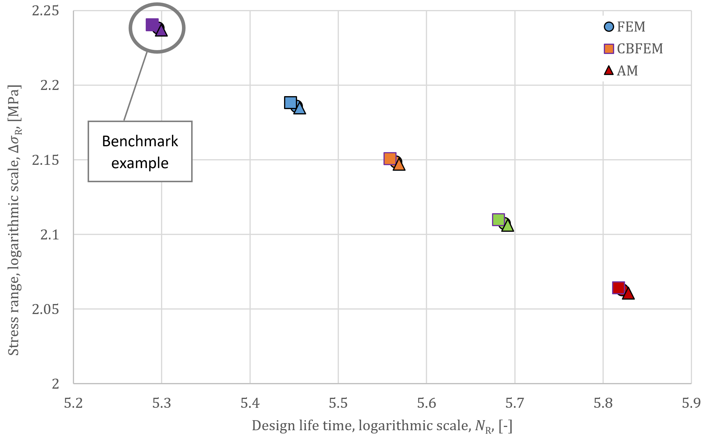
Fig. 5: Comparație a valorilor duratei de viață de calcul NR
3.4. Exemplu de referință
Date de intrare
Plăci:
- Oțel S235
- Placă 90 × 10 mm
Sudură:
- Grosimea de gât = 4 mm
Efecte ale încărcărilor:
- \(F_{min}= 9\textrm{ kN}\)
- \(F_{max}= 99\textrm{ kN}\)
Rezultate
- Tensiunea normală minimă: \(\sigma_{min}= 10.1\textrm{ MPa}\)
- Tensiunea normală maximă: \(\sigma_{max}= 110.9\textrm{ MPa}\)
- Valoarea caracteristică a domeniului tensiunii nominale: \(\Delta \sigma_{E,2}= 100.8\textrm{ MPa}\)
- Valoarea de calcul a domeniului tensiunii nominale: \(\Delta \sigma_{R}= 115.9\textrm{ MPa}\)
- Valoarea de referință a rezistenței la oboseală: \(\sigma_c= 80\textrm{ MPa}\)
- Panta curbei de rezistență la oboseală: \(m=3\)
- Durata de viață de calcul \(N_R=6.57\cdot 10^5\)
4. Îmbinare T sudată cu placă longitudinală
4.1. Descriere
O placă longitudinală cu dimensiunile 100 x 8 mm este sudată la o placă cu dimensiunile 40 x 8 mm prin suduri de colț cu grosimea de gât de 4 mm; vezi Fig. 6. Ambele plăci sunt din oțel S355. Îmbinarea este încărcată cu forță de întindere.
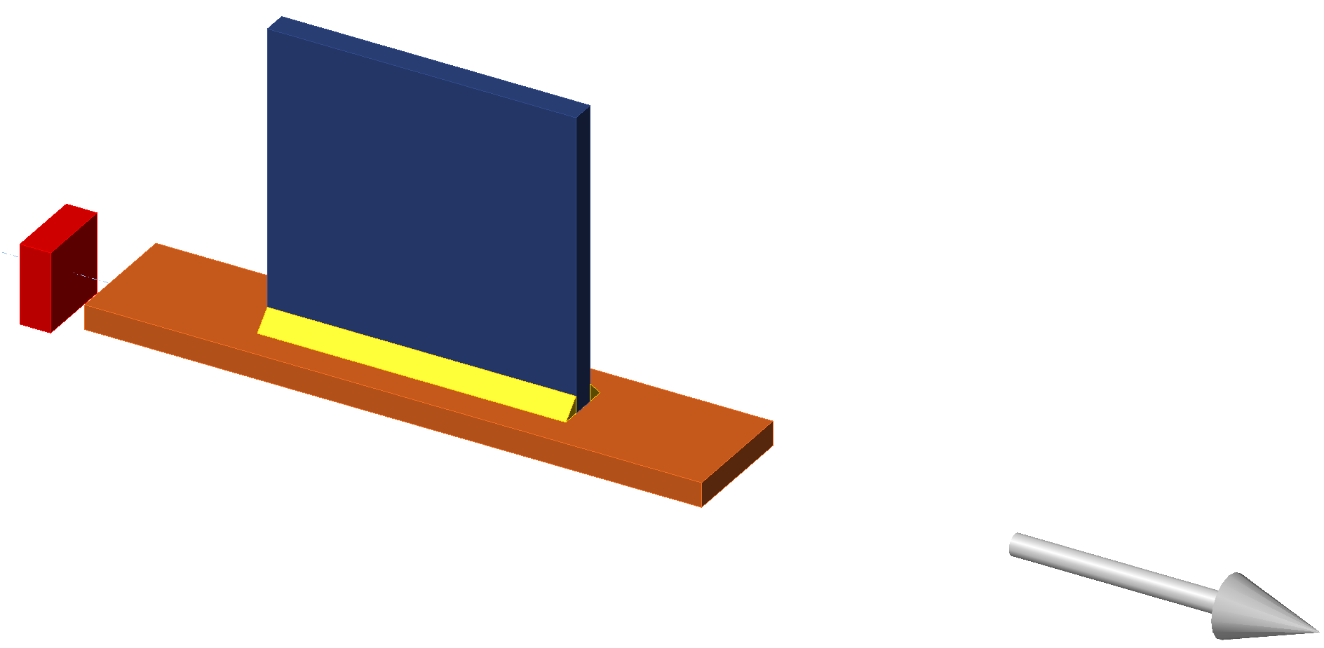
Fig. 6: Îmbinare T sudată cu placă longitudinală
Conform EN 1993-1-9:2005, această îmbinare este detaliul de construcție 1 din tabelul 8.4. Categoria sa de detaliu este 63, deoarece \(L=100 \textrm{ mm}\), adică \(80<L<100\textrm{ mm}\).
4.2. Modele analitice și numerice
Aria secțiunii transversale a plăcii, pentru acest calcul analitic, este A = 320 mm2. Secțiunile de oboseală sunt create utilizând un plan de lucru la o distanță de 40 mm față de marginea sudurii pentru a evita influența tensiunii de vârf din geometria locală a sudurii. Rezultatele modelului analitic AM, modelului solid MEF și modelului de placă CBFEM sunt prezentate în Tab. 5.
Tab. 5: Rezultatele soluțiilor
| AM | FEM | CBFEM | |||||
| \(F_{max}\) | \(F_{min}\) | \(\Delta \sigma_R\) | \(N_R\) | \(\Delta \sigma_R\) | \(N_R\) | \(\Delta \sigma_R\) | \(N_R\) |
| [kN] | [kN] | [MPa] | [-] | [MPa] | [-] | [MPa] | [-] |
| 34 | 3.4 | 110.0 | 3.76E+05 | 129.4 | 2.31E+05 | 110.2 | 3.74E+05 |
| 37.5 | 3.8 | 121.3 | 2.8E+05 | 142.6 | 1.72E+05 | 121.2 | 2.81E+05 |
| 41.7 | 4.2 | 134.7 | 2.05E+05 | 158.6 | 1.25E+05 | 135.0 | 2.03E+05 |
| 44.5 | 4.5 | 143.8 | 1.68E+05 | 169.1 | 1.03E+05 | 143.9 | 1.68E+05 |
| 49.8 | 5.0 | 161.0 | 1.2E+05 | 189.4 | 7.36E+04 | 161.2 | 1.19E+05 |
4.3. Verificare
Calculul numeric CBFEM este verificat pe modele analitice și numerice MEF în funcție de domeniul tensiunii și durata de viață la oboseală, vezi Tab. 5 și Fig. 7. Diferența maximă și medie a tensiunii față de modelul analitic este de aproximativ 1%. Diferența dintre MEF și CBFEM este mai mare datorită diferenței dintre modelul solid și cel de placă și modului în care este luată în considerare excentricitatea.
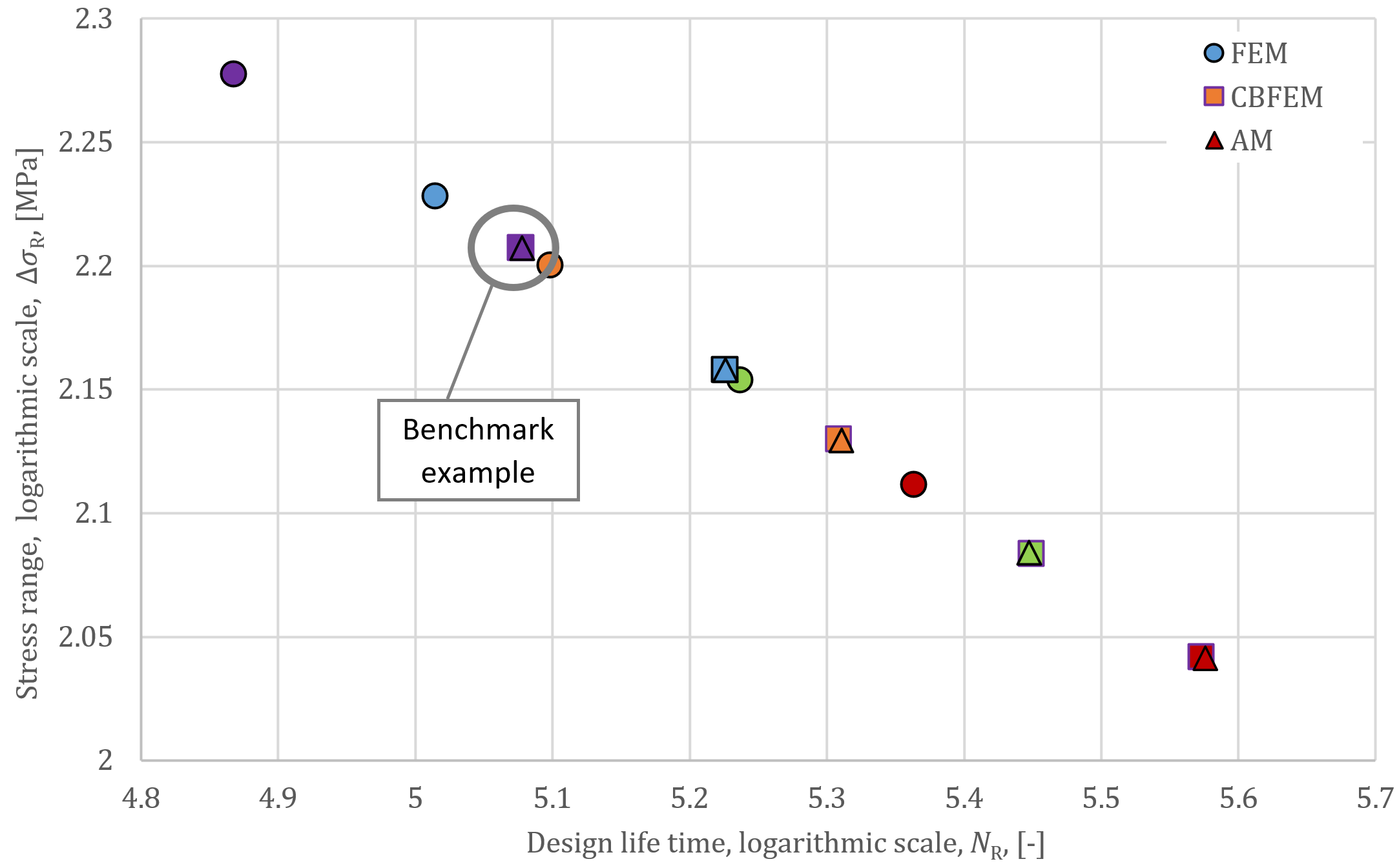
Fig. 7: Comparație a valorilor duratei de viață de calcul NR
4.4. Exemplu de referință
Date de intrare
Plăci:
- Oțel S355
- Placă 40 × 8 mm
- Placă 100 × 8 mm
Sudură:
- Grosimea de gât a sudurii = 4 mm
Efecte ale încărcărilor:
- \(F_{min}= 3.4\textrm{ kN}\)
- \(F_{max}= 34\textrm{ kN}\)
Rezultate
- Tensiunea normală minimă: \(\sigma_{min}= 10.6\textrm{ MPa}\)
- Tensiunea normală maximă: \(\sigma_{max}= 106.4\textrm{ MPa}\)
- Valoarea caracteristică a domeniului tensiunii nominale: \(\Delta \sigma_{E,2}= 95.8\textrm{ MPa}\)
- Valoarea de calcul a domeniului tensiunii nominale: \(\Delta \sigma_{R}= 110.2\textrm{ MPa}\)
- Valoarea de referință a rezistenței la oboseală: \(\sigma_c= 63\textrm{ MPa}\)
- Panta curbei de rezistență la oboseală: \(m=3\)
- Durata de viață de calcul \(N_R=3.74\cdot 10^5\)
5. Îmbinare T sudată cu placă transversală
5.1. Descriere
O îmbinare T sudată cu o placă cu dimensiunile 50 x 12 mm și o placă transversală cu dimensiunile 50x10 mm sunt realizate din oțel S355 prin suduri de colț cu grosimea de gât de 5 mm; vezi Fig. 8. Îmbinarea este încărcată cu forță de întindere.
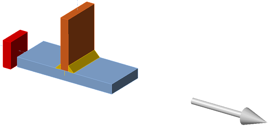
Fig. 8. Îmbinare T sudată cu placă transversală
Conform EN 1993-1-9: 2005, această îmbinare este detaliul de construcție 6 din Tabelul 8.4. Categoria sa de detaliu este 80, deoarece \(l=\textrm{grosimea plăcii}+2\times \textrm{grosimea sudurii}= 20\, \textrm{mm}\), adică \(l<50\,\textrm{mm}\).
5.2. Modele analitice și numerice
Aria secțiunii transversale a plăcii, pentru acest calcul analitic, este A = 600 mm2. Secțiunile de oboseală sunt create utilizând secțiuni de sudură la o distanță de 5t față de marginea sudurii pentru a evita influența tensiunii de vârf din geometria locală a sudurii (\(5t=60\textrm{ mm} > t=50\textrm{ mm}\)). Rezultatele modelului analitic AM, modelului solid MEF și modelului de placă CBFEM sunt prezentate în Tab. 6.
Tab. 6: Rezultatele soluțiilor
| AM | FEM | CBFEM | |||||
| \(F_{max}\) | \(F_{min}\) | \(\Delta \sigma_R\) | \(N_R\) | \(\Delta \sigma_R\) | \(N_R\) | \(\Delta \sigma_R\) | \(N_R\) |
| [kN] | [kN] | [MPa] | [-] | [MPa] | [-] | [MPa] | [-] |
| 94.1 | 9.4 | 162.3 | 2.39E+05 | 155.0 | 2.75E+05 | 162.8 | 2.37E+05 |
| 117.8 | 11.8 | 203.2 | 1.22E+05 | 194.0 | 1.4E+05 | 203.8 | 1.21E+05 |
| 140.7 | 14.1 | 242.8 | 7.16E+04 | 231.8 | 8.23E+04 | 243.3 | 7.11E+04 |
| 152.0 | 15.2 | 262.2 | 5.68E+04 | 250.3 | 6.53E+04 | 263.0 | 5.63E+04 |
| 160.0 | 16.0 | 276.0 | 4.87E+04 | 263.5 | 5.6E+04 | 276.9 | 4.82E+04 |
5.3. Verificare
Calculul numeric CBFEM este verificat pe modele analitice și numerice MEF în funcție de domeniul tensiunii și durata de viață la oboseală, vezi Fig. 9 și Tab. 6. Diferența maximă și medie a tensiunii față de modelul analitic este de aproximativ 1%. În acest caz, excentricitatea nu are o influență semnificativă; diferența dintre MEF și CBFEM este de aproximativ 5%.
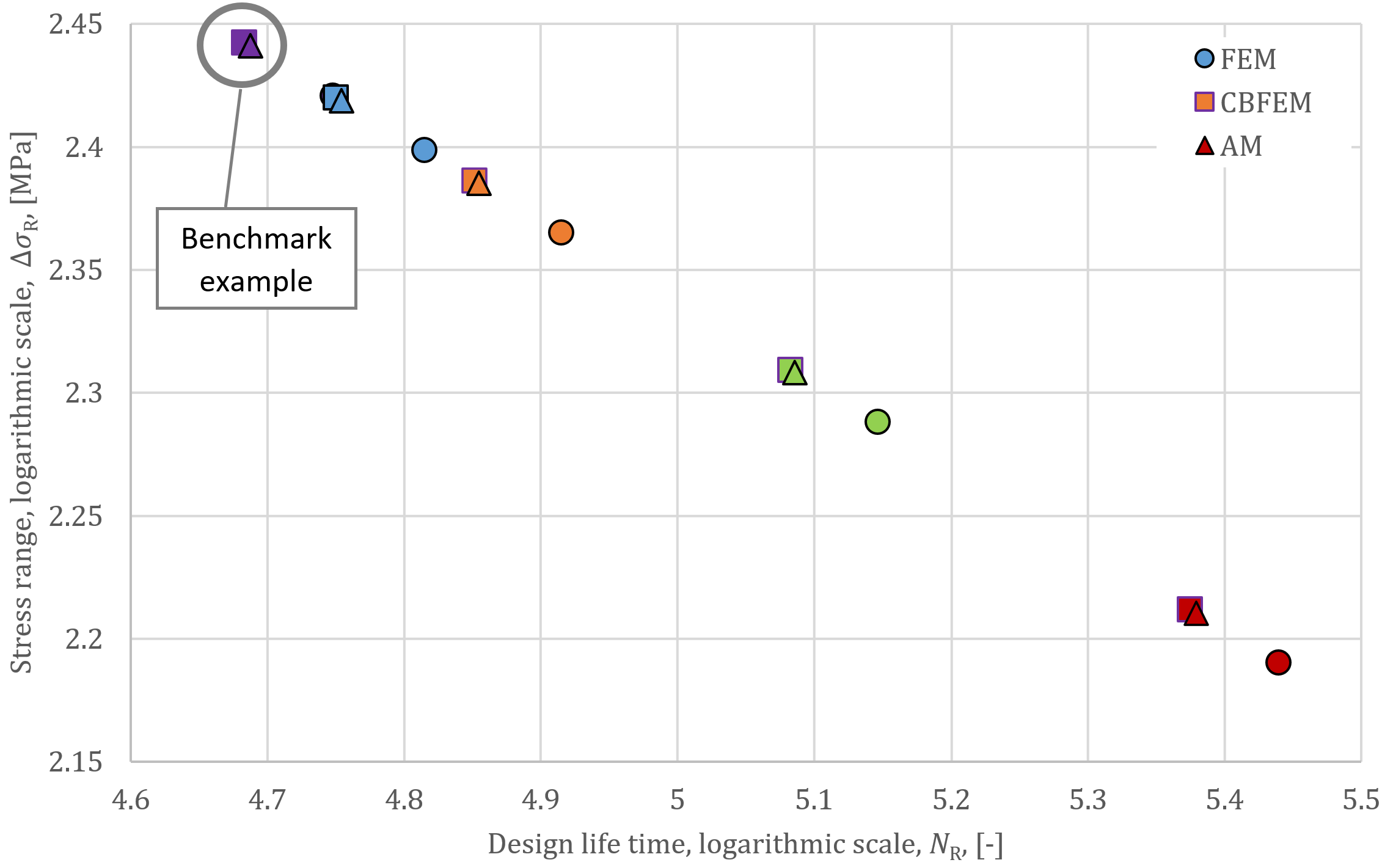
Fig. 9: Comparație a valorilor duratei de viață de calcul NR
5.4. Exemplu de referință
Date de intrare
Plăci:
- Oțel S355
- Placă 50 × 12 mm
- Placă transversală 50 × 10 mm
Sudură:
- Grosimea de gât = 5 mm
Efecte ale încărcărilor:
- \(F_{min}= 9.4\textrm{ kN}\)
- \(F_{max}= 94.1\textrm{ kN}\)
Rezultate
- Tensiunea normală minimă: \(\sigma_{min}= 15.7\textrm{ MPa}\)
- Tensiunea normală maximă: \(\sigma_{max}= 157.3\textrm{ MPa}\)
- Valoarea caracteristică a domeniului tensiunii nominale: \(\Delta \sigma_{E,2}= 141.6\textrm{ MPa}\)
- Valoarea de calcul a domeniului tensiunii nominale: \(\Delta \sigma_{R}= 162.8\textrm{ MPa}\)
- Valoarea de referință a rezistenței la oboseală: \(\sigma_c= 80\textrm{ MPa}\)
- Panta curbei de rezistență la oboseală: \(m=3\)
- Durata de viață de calcul \(N_R=2.37\cdot 10^5\)
Exemplele de verificare au fost pregătite de Kirill Golubiatnikov la Universitatea Tehnică Cehă din Praga.