Lassen – automatisch ontwerp, invoer, waarschuwingen, visualisatie
Dit artikel bevat verouderde informatie. Raadpleeg de bijgewerkte versie.
Gebruikergedefinieerde laselektroden
Lasmateriaal is een bewerkbaar item in de MPRL (Material and Product Range Library). Dit betekent dat u de laselektroden onafhankelijk van de staalsoort van de verbonden platen kunt definiëren.
Om een gebruikergedefinieerd lasmateriaal toe te voegen, gaat u naar het tabblad Materialen, voegt u een Lasmateriaal toe en Bewerkt u de eigenschappen.
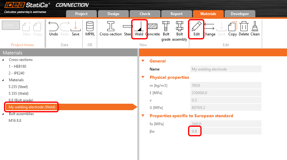
Ook kan de correlatiefactor βw worden aangepast van de standaardwaarde van 0,8 om overeen te komen met waarden voor bijvoorbeeld roestvast staal (βw = 1,0 voor lassterkte lager dan 360 MPa).
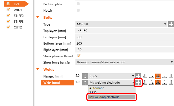
U kunt vervolgens het laselektrodemateriaal toewijzen via een keuzelijst van elke las van elke bewerking. U kunt ook een nieuw lasmateriaal toevoegen.
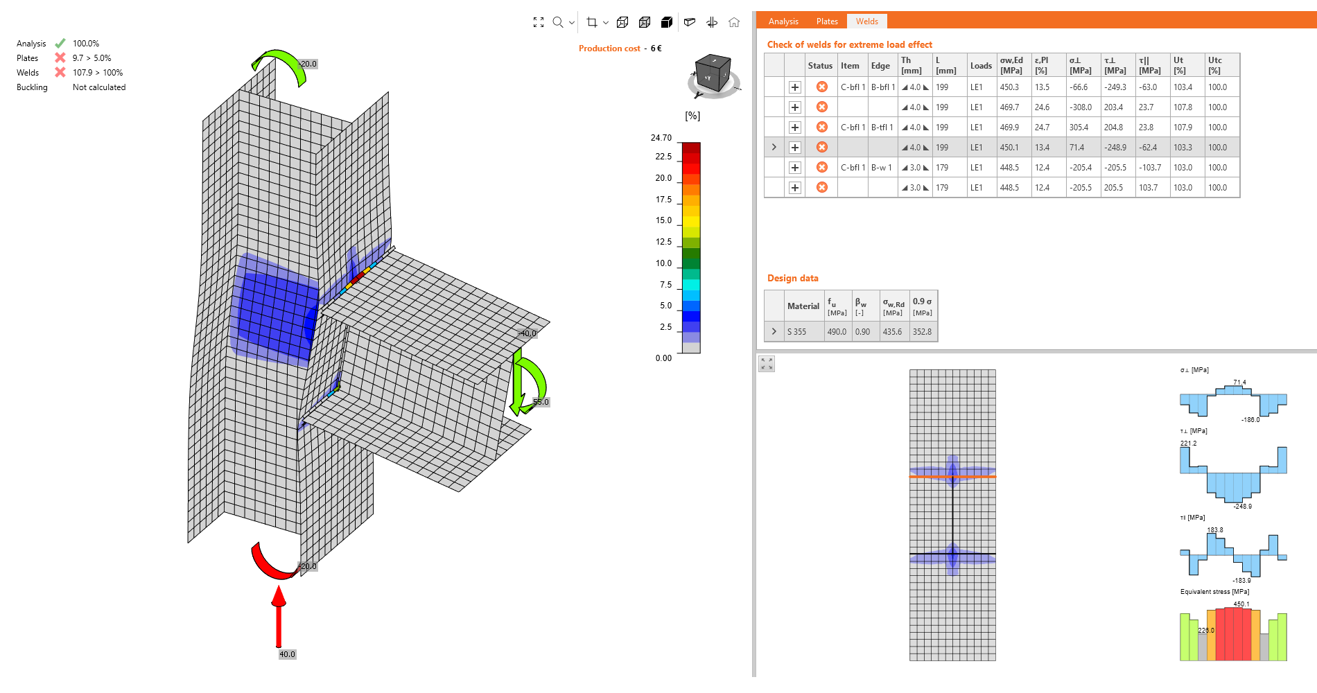
Controletabellen en het rapport zijn uitgebreid om altijd informatie te bevatten over de laselektroden en hun parameters.
Automatisch ontwerp van lassen op volledige sterkte
Deze functie stelt gebruikers in staat de lasgrootte te optimaliseren op basis van de sterkte van de gelaste plaat. Dit verkort de ontwerptijd en zorgt voor een veilige lasgrootte voor alle lassen in het verbindingsproject.
U kunt het algoritme Automatisch ontwerp las op volledige sterkte uitvoeren voor alle lassen binnen het verbindingsproject tegelijk via de rechtermuisknop op Bewerkingen in het boomstructuurmenu.
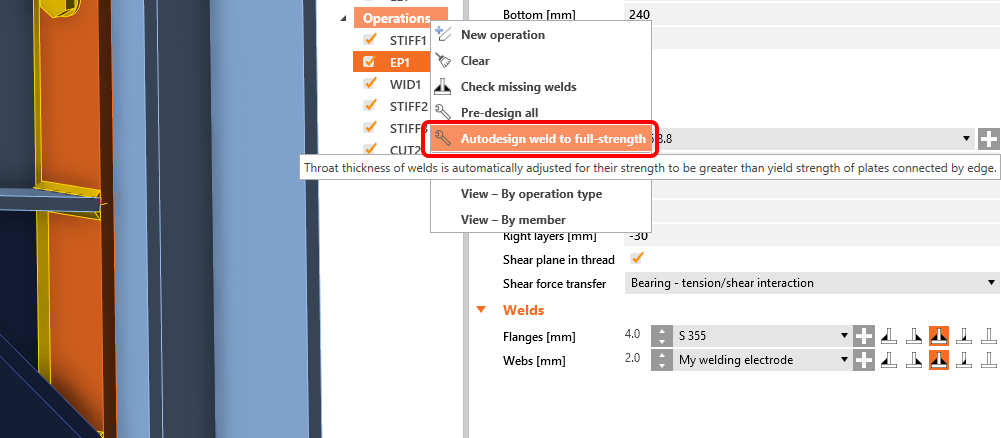
Voor het algoritme gelden de aannames dat de plaat belast wordt in trek (gevaarlijker voor lasontwerpen) en dat de laslengte gelijk is aan de randlengte van de verbonden plaat. De sterkte van de plaat in trek wordt genomen als de lassterkte loodrecht belast, en de lasgrootte wordt vervolgens afgeleid. De invoergegevens zijn:
- Dikte van de verbonden plaat per rand (of de dunnere plaat bij rand-op-rand)
- Vloeigrens van het verbonden plaatmateriaal
- Treksterkte van het lasmateriaal
- Overige lasparameters (factoren, coëfficiënten, bijv. βw)
- Partiële veiligheidsfactoren voor plaatmateriaal
- Partiële veiligheidsfactoren voor lasmateriaal
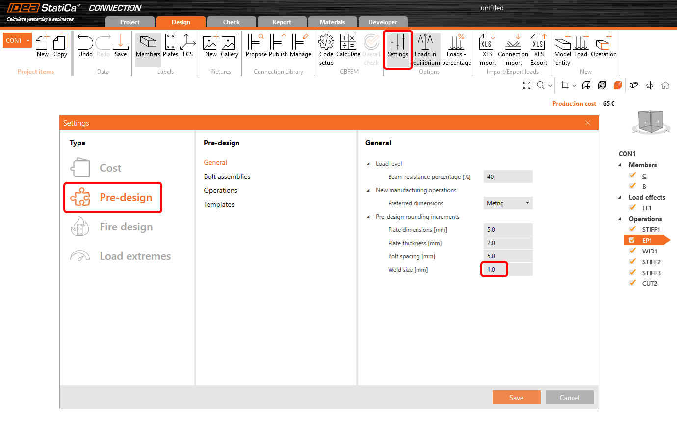
Afronding van de laskeeldikte of de lasvoetwaarde kan worden ingesteld in Instellingen, Voorontwerp en Lasgrootte.
Schatting van de totale capaciteit van een las
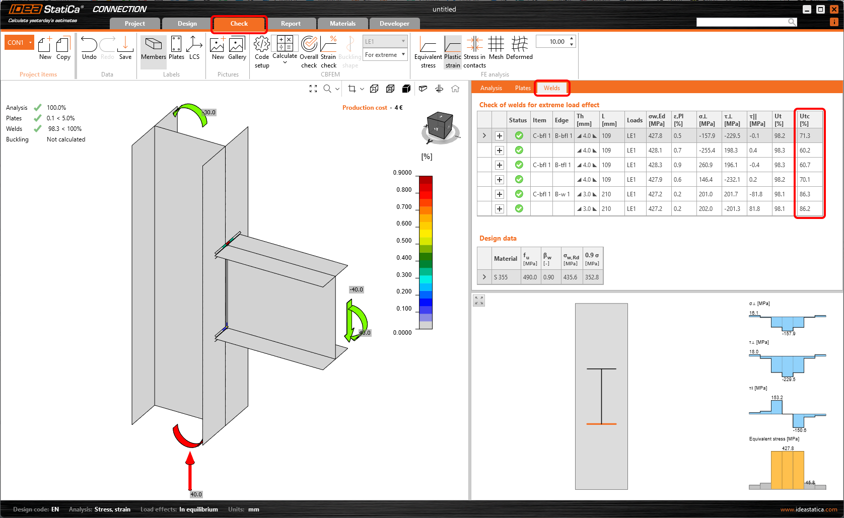
In het resultatenblad voor lassen worden twee benuttingsgraden weergegeven. De Ut (spanningsbenutting) toont de benuttingsgraad van het meest belaste eindige element van de gehele las (piekwaarde), terwijl de Utc (laskapaciteitsbenutting) de benutting van de gehele las weergeeft en de gebruiker zo informatie geeft over de resterende lascapaciteit.
Omdat de spanningsverdeling in lassen in op de Eindige Elementen Methode gebaseerde modellen onzeker varieert op basis van de aangebrachte belasting, is het niet eenvoudig om de resterende capaciteit als een lineaire functie te bepalen. Bij een toename van de aangebrachte belasting kan de verandering in de spanningsverdeling van de las zeer drastisch zijn.
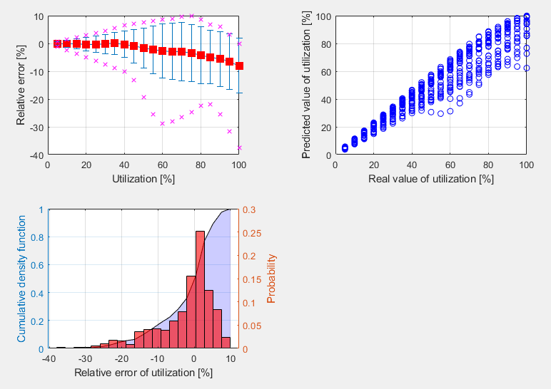
De berekening van Utc maakt gebruik van een machine-learning schattingsfunctie. Op basis van het leren van een groot aantal gelaste verbindingsmodellen en verschillende belastingscenario's kan het algoritme de resterende lascapaciteit nauwkeurig voorspellen. Het getal wordt weergegeven in Controle, in het tabblad Lassen in de kolom Utc.
Deze functionaliteit is het eerste succesvolle gebruik van AI en machine learning om de capaciteit van lassen te bepalen. En het beste is dat de applicatie dit binnen een drempelwaarde van 10% kan doen! Wat als een uitstekend resultaat kan worden beschouwd.
Deze functie is beperkt tot projecten in Eurocode.
Algemene las gemarkeerd in de 3D-weergave
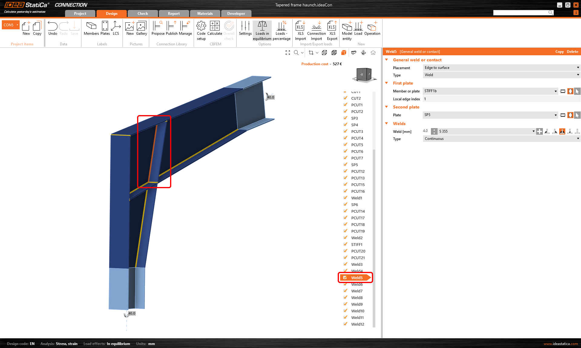
Er is een eenvoudige verbetering in de 3D-weergave van de Connection app voor een betere oriëntatie, vooral in grotere verbindingsmodellen geïmporteerd via BIM-koppelingen vanuit CAD-applicaties.
Wanneer een Algemene las of contactbewerking is geselecteerd, wordt de las in de 3D-weergave oranje gemarkeerd (standaard).
Waarschuwing voor elektroden sterker dan platen
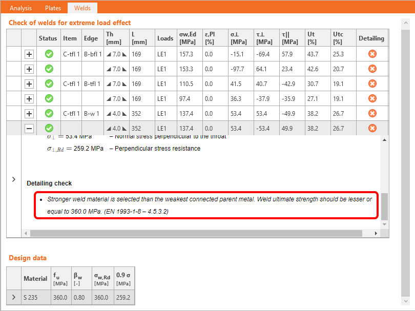
Wanneer de Detaillering normtoetsing is geactiveerd in de Norminstelling van de Connection app, krijgen gebruikers een waarschuwing als een laselektrodemateriaal sterker is dan de gelaste platen. Dit helpt om ontwerpveiligheidsnormen te waarborgen.
Dit is van toepassing op Eurocode (EN) en de Indiase norm (IS), die clausules bevatten die bepalen dat de lassterkte wordt bepaald door de kleinste treksterkte van de verbonden platen en vereisten dat het toegevoegde materiaal van laselektroden sterker moet zijn dan het basismateriaal (EN 1993-1-8 – 4.5.3.2 en IS 800:2007 - 10.5.7.1.1).
Verbetering van het EEM-model voor stompe lassen
Het eindige-elementenmodel van stompe lassen is bijgewerkt. Het model van stompe lassen lijkt nu op het model van hoeklassen, waardoor het voor de automatische entiteitsgenerator eenvoudiger is om een stompe las te genereren onder bepaalde omstandigheden, met name voor kokerprofielen.
Verbeterde visualisatie van lascontrole
Lascontrole met behulp van een eindige-elementenmethode verschilt van traditionele ontwerpberekeningen. In traditionele berekeningen kunnen kleine excentriciteiten, vervormingen, torsies en Poisson-coëfficiënten, enz., worden verwaarloosd.
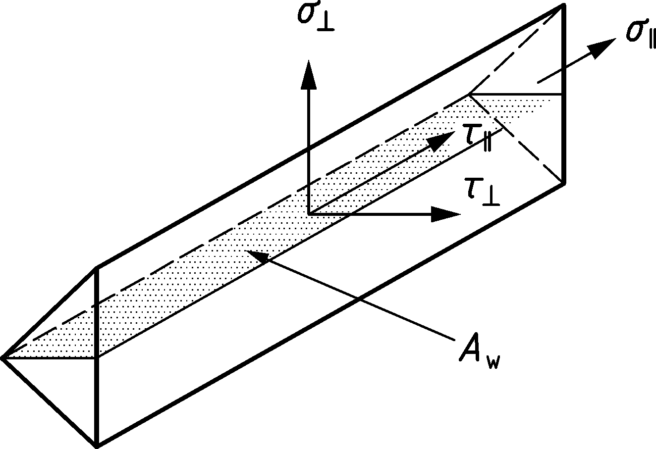
Spanningscomponenten worden nu weergegeven:
- σꓕ
- τꓕ
- τ‖
Deze spanningen worden in alle normen gebruikt voor verdere lasevaluatie.
Equivalente spanning wordt grijs/groen/oranje/rood gekleurd volgens het Waarschuwings- en Optimaal controleniveau (bewerkbaar in Norminstelling) voor een betere duidelijkheid.
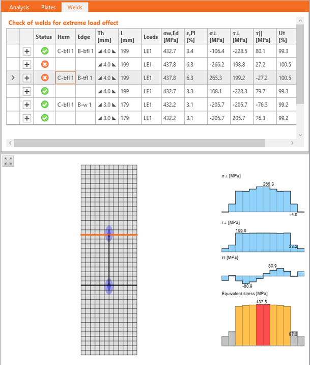
Deze verbeterde functionaliteit helpt ingenieurs de spanningen in gelaste verbindingen te begrijpen.
Beschikbaar in IDEA StatiCa Steel en IDEA StatiCa Complete edities.