Gelaste lasverbinding (AISC)
Sub-code: LRFD
Type verbinding: Concentrisch belaste multi-georiënteerde lasgroep
Eenheidssysteem: Metrisch
Ontworpen volgens: AISC 360-16
Onderzocht: Lassen
Plaatmaterialen: Plaat en kolom – ASTM A572 – Gr. 50
Lassen: Lasnaaddikte = 3 mm, elektrode E70XX
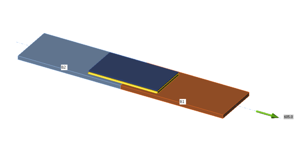
Geometrie:
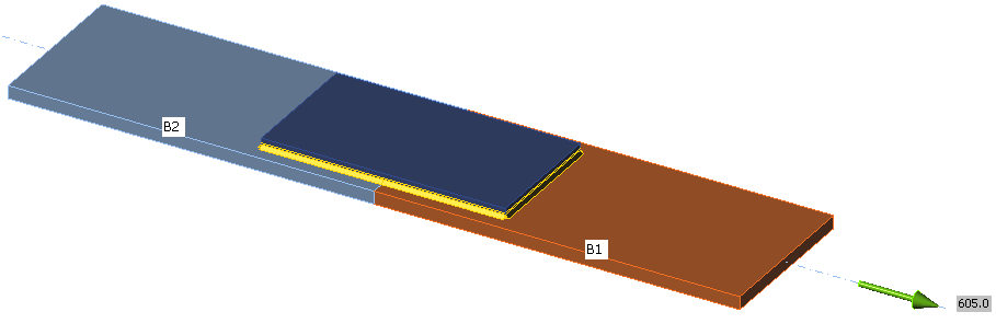
Staafdikte: 16 mm
Lasplaatdikte: 12 mm
Toegepaste krachten:
Eenvoudige gelaste verbindingen worden belast door trek om 100% te benutten. Lassen zijn ontworpen als het zwakste onderdeel.
Procedure:
Een concentrisch belaste lasverbinding met lasgroepen bestaande uit elementen met een uniforme lasnaaddikte die zowel longitudinaal als transversaal ten opzichte van de belastingsrichting zijn georiënteerd, wordt belast door trek en is zodanig ontworpen dat de lassen als eerste bezwijken. De verbinding wordt belast zodat de lassen 100 % worden benut en de belasting wordt vergeleken met de lasweerstand volgens AISC 360-16 – J.2.4.
Handberekening
De gecombineerde sterkte van de lasgroep wordt bepaald volgens AISC 360-16 – J.2.4 (2).

De sterkte van het basismateriaal hoeft niet te worden beoordeeld bij gebruik van overeenkomende elektroden, maar wordt hier ter verificatie weergegeven.
Een voorbeeld van een lasverbinding met een lengte van de longitudinale lassen van 150 mm en een lengte van de transversale lassen van 160 mm is weergegeven in de onderstaande tabel:

Vergelijking:

De resultaten van zowel het IDEA StatiCa Connection ontwerp als de berekening volgens AISC 360-16 geven nagenoeg identieke waarden voor de sterkte van het lasmetaal (98–101%). Met inachtneming van de controle van het basismateriaal is IDEA licht conservatief (93–94%). Door gebruik te maken van de eindige elementen analyse en de benadering waarbij het meest belaste element van de las wordt gecontroleerd, is er geen handmatige reductie van de lasweerstand vanwege de lasoriëntatie nodig.