Supports and load transmitting components
To model most of the situations during the construction process, many types of supports (Fig. 7) and components used for transferring load (Fig. 8) are available in the CSFM.
Supports
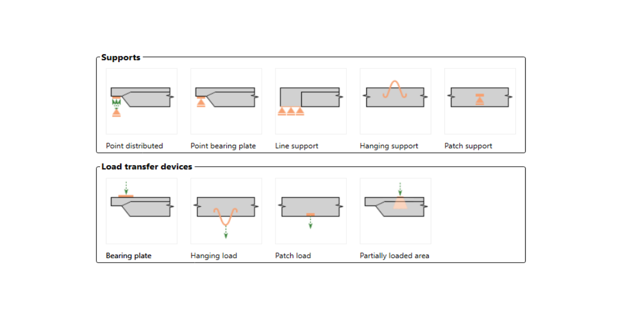
Point support can be modeled in several ways to ensure that stresses are not localized in one point but rather distributed over a larger area. The first option is a distributed point support (Fig. 7a), which uniformly distributes the load on the edge of the member over the specified width.
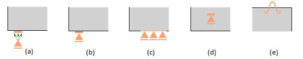
\[ \textsf{\textit{\footnotesize{Fig. 7\qquad Various types of supports:}}}\]
\[ \textsf{\textit{\footnotesize{(a) point distributed; (b) bearing plate; (c) line support; (d) patch support; (e) hanging.}}}\]
Patch support (Fig. 7d), on the other hand, can only be placed inside a volume of concrete with a defined effective radius. It is then connected by rigid elements to the nodes of the reinforcement mesh within this radius. Therefore, it is required to define a reinforcing cage around patch support.
For the more precise modeling of some real scenarios, there are two other options for point support. Firstly, there is point support with a bearing plate of defined width and thickness (Fig. 7b). The material of the bearing plate can be specified, and the whole bearing plate is meshed independently. Secondly, there is hanging support available (Fig. 7e), which can be used for modeling lifting anchors or lifting studs.
Line support (Fig. 7c) can be defined on an edge (by specifying its length) or inside an element (by a polyline). It is also possible to specify its stiffness and/or non-linear behavior (support in compression/tension or only in compression).
- Read detailed descriptions in Types of supports in IDEA StatiCa Detail
Load transmitting components
The introduction of loads into the structure can also be modeled in several ways. For point loads, a bearing plate (Fig. 8a) can be used similarly as point support, distributing the concentrated load onto a larger area thanks to a steel plate with defined width and thickness.
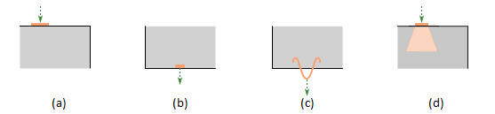
\[ \textsf{\textit{\footnotesize{Fig. 8\qquad Various types of load transfer components:}}}\]
\[ \textsf{\textit{\footnotesize{(a) bearing plate; (b) patch load; (c) hanging; (d) partially loaded area.}}}\]
The point load can be applied either directly to the surface of the structure with a defined radius of action (load is applied to the concrete elements) or via a special transmitting device called patch load (Fig. 8b and Fig. 9). Patch load allows transmitting the load directly to the defined reinforcement located within the area of the effective radius. To secure the correct functionality of the patch load, a group of rebars that will be interconnected with the load is necessary to define (in the reinforcement properties). When the interconnected reinforcement is not defined, the load transfer mechanism is the same as for the point load placed on a member surface, and the load is transferred by the constraints to the concrete elements, not directly to the reinforcement.
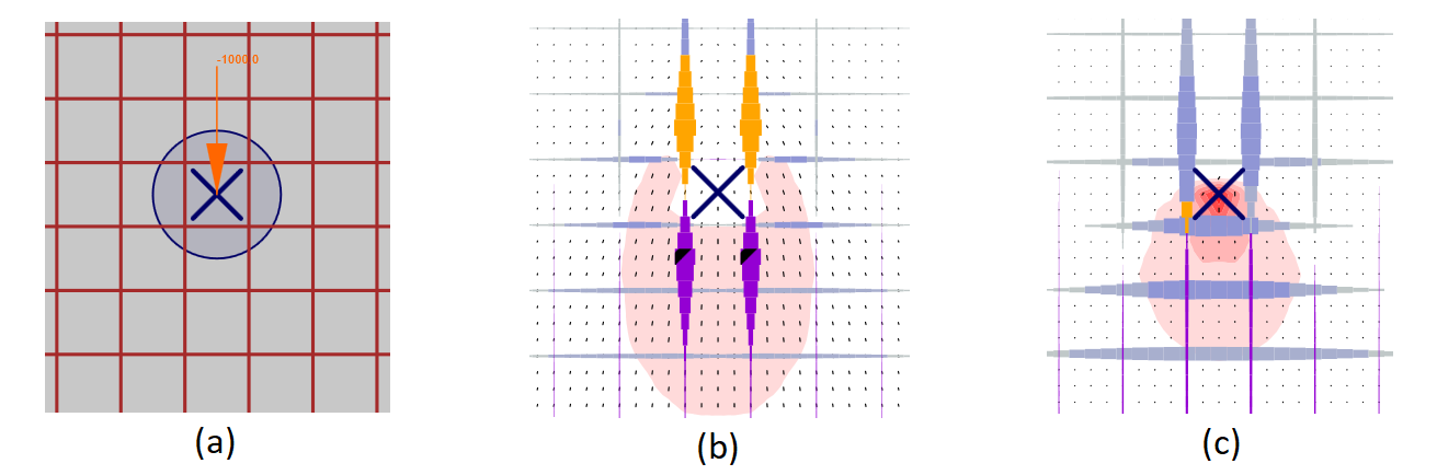
\[ \textsf{\textit{\footnotesize{Fig. 9\qquad Patch load: (a) load application; (b) load transferred through rebars (a group of bars for the load transfer is defined);}}}\]
\[ \textsf{\textit{\footnotesize{(c) load transferred through concrete (a group of bars for the load transfer is not defined).}}}\]
Lifting anchors or lifting studs can be modeled by a hanging load (Fig. 8c). User can use a partially loaded area (Fig. 8d), which allows for increasing the load-bearing capacity of concrete in compression according to Eurocode (it is not possible to use this type of load transmitting component when ACI is set). The structure can also be loaded with line loads on the edges, by general polyline, or by surface loads. The Detail application is able to automatically consider a self-weight in the analysis.