
MIDAS GEN NX BIM link for steel connection design
1 Activation
Since version MIDAS GEN NX 2026 (V1.1) and newer, the API has been added, and due to this new possibility, the new link to IDEA Statica Checkbot was created.
In the following figures, you can see how to activate the link.

Press YES when the User Account Control asks for permission to make changes to your device.
Install the Midas GEN NX BIM link.

Subsequently, the new icon appears on the Desktop.

Now run Midas GEN NX and open the new or existing project.
In the ribbon, in the last tab APPs, there is API Settings, where the Base URL and MAPI-Key are given. At first, the MAPI-Key is blank; it must be generated by clicking the Refresh button. The MAPI-Key is unique for every user and shouldn´t be shared with others. The Copy button can be used to copy them.
Connect to the API.

The API is connected when the Tab changes to "Disconnect".

Open the IDEA to MIDAS GEN NX Integration Tool from the Desktop and paste the copied Base URL and MAPI Key from your opened MIDAS GEN NX project (1). Then, Validate (2) and connect to Civil NX (3). After that, Start Checkbot (4).

Select the path to the active MIDAS GEN NX file and open it. Both .mgb and .mgbz file formats can be chosen.

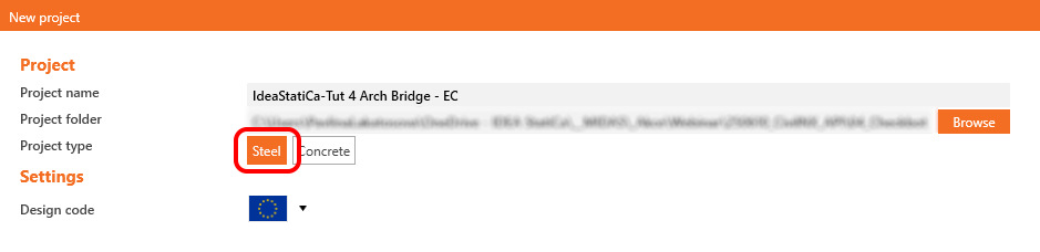
Create the New project in Checkbot.

The Checkbot folder is created in the same folder as the MIDAS GEN NX project.

After that, a new project is opened. The Checkbot is connected to GEN NX (look at the bottom right corner).

2 Import to Checkbot
At first, run the linear analysis in GEN NX to get the internal forces.
After analysis, you can import the whole model. To do so, select all the elements.

Click on the Connections Import tab.

The whole structure has been imported.

Alternatively, the connections could be imported one by one by selecting only one or more connections. The connections of the same typology are sorted into one arrangement or group.
More about the workflow in the Checkbot, see the article Checkbot – bulk BIM workflows.
Grouping
The software groups connections by topology and cross-sections. The system automatically designates the Reference connection (visually distinguished by an underlined name in Three). This assignment is fixed and cannot be changed manually.
- Reference connection: Fully editable source of the design.
- Child connections: Non-editable duplicates of the Reference.

Operations, settings, and model types defined in the Reference are automatically applied to all Child connections. To modify a Child connection independently, use the right-click menu to Remove from group. This action disconnects it from the Reference and clears any inherited operations.
You can also create custom groups to organize the project as needed. To designate a specific connection as the Reference, first create a group containing only that target connection. Then, add the remaining connections to this new group. You can also select and assign multiple connections to a group simultaneously.

Known limitations
- For now, importing only steel connections (no concrete) is possible.
- All nodes are imported as connections.
Also, the intermediate nodes are imported as connections.
- Only simple combinations.
Creating the load combinations in midas GEN NX is based on combining previously defined combinations (Add and Envelope). For now, the BIM link doesn’t allow the import of these multilevel combinations, but allows the import of only two “single-level” types of load combinations:
- Basic Add combination – means linear combinations of only individual load cases. No Add combination, Envelope combination, Moving load, or Settlement load can be included in the imported combination.
- Basic Envelope combination – means a simple Envelope of only individual load cases. No Add combination, Envelope combination, Moving load, or Settlement load can be included in the imported combination.
For example, in the case of the moving load, the user has to create a linear load case that causes extreme internal forces in the connection (by the Moving Load Tracer feature, for example), and then use this load case in the add combination.

- Nodal loads are not imported; only internal force imports are available.
This limitation could cause unbalanced forces in the connection due to nodal loads being entered directly in the node, which basically do not create internal forces on the members.
