Qualification checks of seismic prequalified connections for AISC
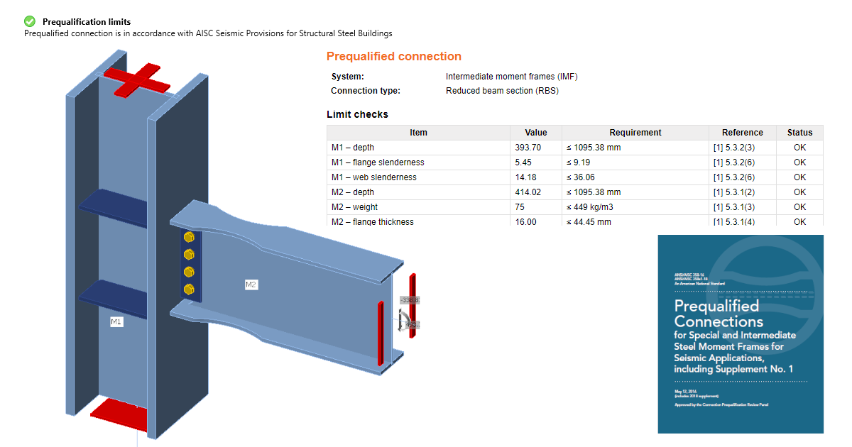
The results of the checks are listed in a new table in the report with all the necessary information to prove that the requirements of prequalified connections design of the code ANSI/AISC 358-16 have been fulfilled.
The checking of the code requirements is done in real-time. Short messages displayed directly on the 3D scene help the designer create the connection design in a more efficient way with significant time savings.
This new feature is intended as a check of scope of prequalification for all engineers who perform structure designs and analysis of structures according to the AISC codes for seismic design.
Theoretical background
Standard ANSI/AISC 358-16 specifies the design, detailing, fabrication and quality criteria for connections that are prequalified in accordance with the AISC Seismic Provisions for Structural Steel Buildings (herein referred to as AISC Seismic Provisions) for use with special moment frames (SMF) and intermediate moment frames (IMF). The connections contained in this standard are prequalified to meet the requirements in AISC Seismic Provisions only when designed and constructed in accordance with the requirements of this standard.
First setting
There is a new property grid where it is necessary to set the Analysis type to Capacity design and enable the option for Prequalified connection.
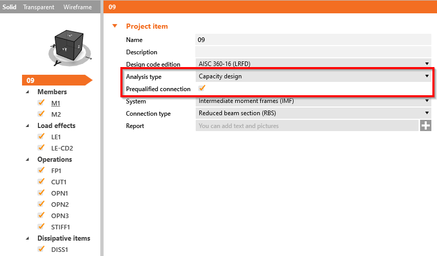
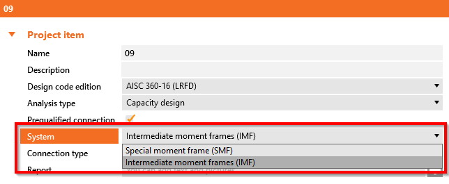
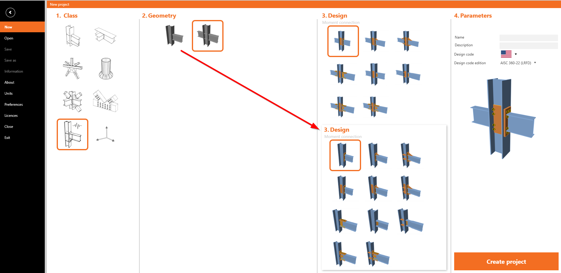
After that, it is possible to select the System and Connection type according to the one in code ANSI/AISC 358-16. There are two possible systems, Special moment frame (SMF) and Intermediate moment frame (IMF)
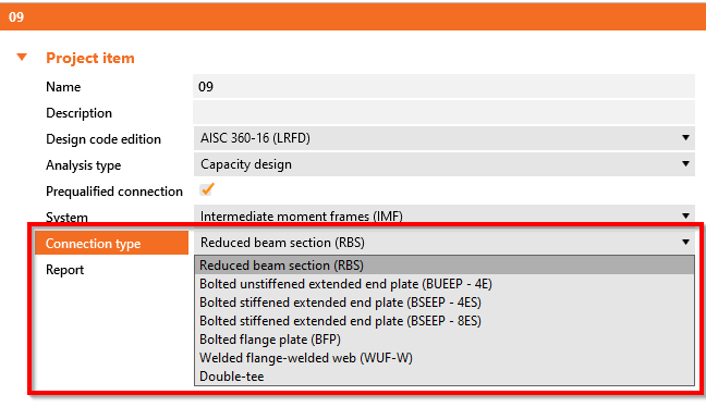
The connection types incorporated into the Connection app were selected based on their frequency of use and usability for analysis in the Connection app. A list of them is shown in the figure below.
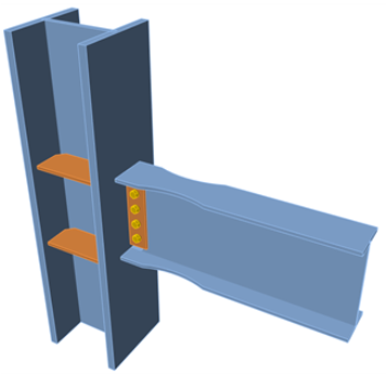
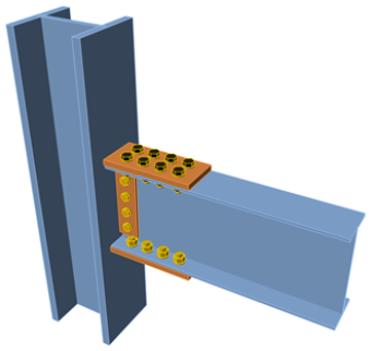
Models for seismic design are proposed in the wizard. The user can choose a single-sided or double-sided beam connected to the column. All these models are set to the proper connection type by default and are set up with appropriate load effects.
Usage
A message regarding the design of the prequalified connection is always displayed to the user.
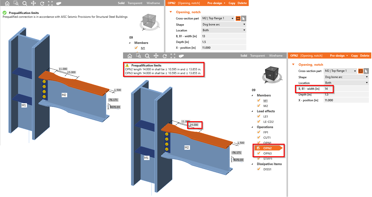
If the design of the prequalified connection meets the code requirements, a green-OK-status message is displayed.
If any of the requirements is not fulfilled, the status of the message is changed to a yellow-exclamation-mark warning and a short message with the specific limitation is displayed. This message provides an immediate response to the designer's action as well as a specific value that needs attention for correction.
Most of the checked values are related to IDEA StatiCa operations. If the design consists of only basic items such as stiffening plate, bolt grip, etc., a generic message can appear directing the user to use IDEA StatiCa's operations instead.
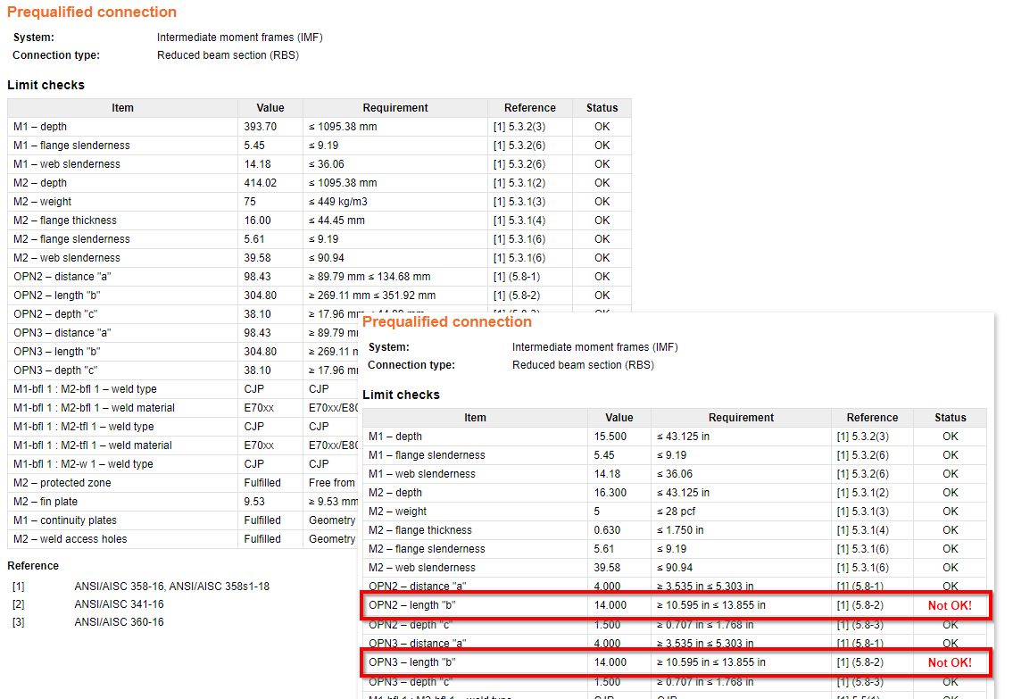
The results of the successful analysis of the detail are presented in the Report. There is a new table where all provided checks are stated. Every check has information about the item, the current value and requested value limit, a reference to the chapter of the code and the status of the check.
The used system and Connection type are also stated.
Specification of the checked requirements
Connection type specific checks and the general checks that are not related to a specific connection type are provided.
General checks
A check of Limiting Width-to-Thickness Ratios is performed according to AISC 341-16: Chapter D.1.1b and Table D1.1. The minimum requested slenderness of the flange and the web of the cross-section is checked.
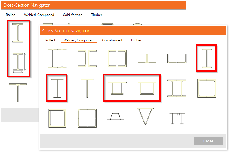
A check of Type of member’s section according to the ANSI/AISC 358-16: Chapter 2.3 is performed. The types of the cross-section used in the members for prequalified design are limited according to the code. In the Connection app, the limitations of the supported cross sections are used for prequalified connection design.
Types of cross-sections used for beams:
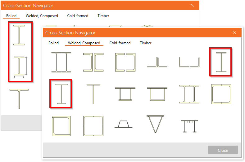
Types of cross-sections usable for columns:
Fastening assemblies are checked according to ANSI/AISC 358-16: Chapter 4.1. There is a list of bolt assemblies dedicated to a prequalified connection.
Protected zones are checked according to ANSI/AISC 341-16: Chapter D1.3.
The geometry of the Continuity plates is checked according to AISC 341-16: Chapter E2.6f.2 and Chapter E3.6f.2.
The geometry of the Doubler plates is checked according to AISC 341-16: Chapter E3.6e.
Specific checks
Reduced Beam Section (RBS)
This Connection type is checked according to Chapter 5 in code ANSI/AISC 358-16. The following checks are provided:
- Checks of the beam limitations according to Chapter 5.3.1.
- Checks of the column limitations according to Chapter 5.3.2.
- Checks of the beam-flange to column weld limitations according to Chapter 5.5 and a related check of the weld access hole according to AISC 360-16: Chapter J1.6.
- A check of the beam-web to column weld limitations according to Chapter 5.6.
- A check of the geometry of the RBS according to Chapter 5.8 Step 1.
The shear strength according to Chapter 5.6 (1) and the weld of the fin plate, according to Chapter 5.6 (2), are stated as out of scope of the check in Connection.
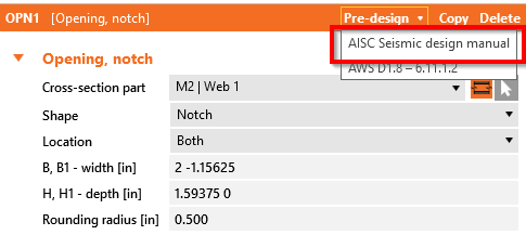
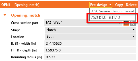
A new feature is prepared for the pre-design of the weld access hole, which is performed in the beam web according to the AISC Seismic Design Manual – Table 1-1. This feature can be used to define the optimal geometry of the weld access hole by software that fulfills the code's requirements.
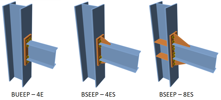
Bolted Unstiffened/Stiffened Extended End Plate (BUEEP – 4E / BSEEP – 4ES / BSEEP – 8ES)
This connection type is checked according to Chapter 6 in code ANSI/AISC 358-16. The following checks are provided:
- Checks of the beam limitations according to Chapter 6.3.1.
- Checks of the column limitations according to Chapter 6.3.2.
- Checks of the connection detailing limitations according to Chapter 6.7 and Table 6.1. This check contains a check of the bolt and end plate geometry, if stiffened, also the stiffener of the end plate.
The finger shims are not supported in the operation and are stated as out of scope of the check in Connection. Also, the check of the welds for the full strength of the beam web in tension, according to the Chapter 6.7.6 (3), is stated as out of scope of the check in Connection.
Bolted Flange Plate (BFP)

This connection type is checked according to Chapter 7 in code ANSI/AISC 358-16. The following checks are provided:
- Checks of the beam limitations according to Chapter 7.3.1.
- Checks of the column limitations according to Chapter 7.3.2.
- Checks of the connection detailing limitations according to Chapter 7.5. This check contains a check of the plate's material, welds and bolt grade and diameter.
Welded Unreinforced Flange-welded Web
This connection type is checked according to Chapter 8 in code ANSI/AISC 358-16. The following checks are provided:
- Checks of the beam limitations according to Chapter 8.3.1.
- Checks of the column limitations according to Chapter 8.3.2.
- Checks of the beam-flange to column weld limitations according to Chapter 8.5. and a related check of the weld access hole according to AWS D1.8/D1.8M: Chapter 6.11.1.2.
- Check of the beam-web to column weld limitations according to Chapter 8.6.
The weld of the single plate to the column according to the Chapter 5.6 (2) is stated as out of scope of the check in Connection.
A new feature is for the pre-designing of the weld access hole, which is performed in the beam web according to AWS D1.8/D1.8M: Chapter 6.11.1.2. This feature can be used to define the optimal geometry of the weld access hole using the software, which fulfills the code requirements.
Double-tee

This connection type is checked according to Chapter 13 in code ANSI/AISC 358-16. The following checks are provided:
- Checks of the beam limitations according to Chapter 13.3.1.
- Checks of the column limitations according to Chapter 13.3.2.
- Checks of the connection detailing limitations according to Chapter 13.5. This check contains a check of the continuity plates', welds' and bolts' geometry and grade.
Available in Enhanced edition of IDEA StatiCa Steel.