Enhanced modeling features in steel
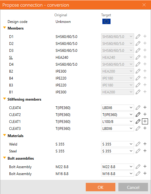
Template application dialog with sketches and parameters
Enhanced sketches or, in other words, simple drawings of connections, can be added and printed in the final report. Any defined sketch (user-defined section) can be a part of the design template published in the Connection Library.
When such a design template is applied to a new connection model, the a conversion dialog pops up enabling users to:
- See the design standard of the template and the design standard of the current project
- See an overview of members, which one is bearing (underscored), and the mapping between them
- Control mapping of stiffening members
- Each operation has its own row
- Each operation can have an assigned new CSS, which will be added to the project
- Control the mapping of materials (welds, steel, concrete ...)
- Control the bolt assemblies' mapping
- Control pins mapping
- Ensure that, together with the template, the parameters and parametric properties are copied
- Produce sketched together with the template
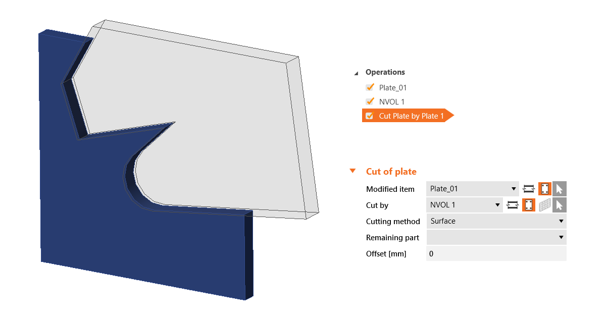
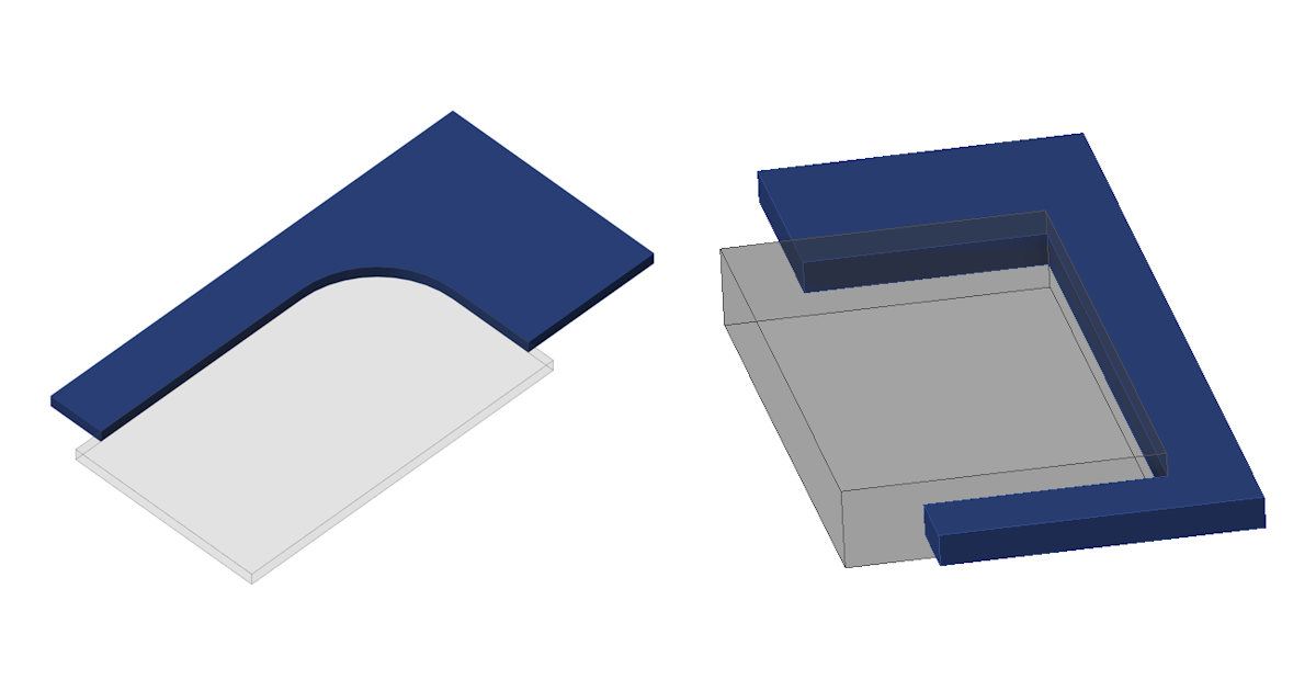
Execute plate cuts in parallel planes
IDEA StatiCa supports the capability to execute plate cuts in parallel planes.
The Cut of plate operation offers the possibility to cut plates by other plates and negative volumes defined within the same plane. This is beneficial for handling general plate shapes imported from DXF files, addressing the plate cuts that could not be performed in the plate Editor.
To use this feature, select the PCUT (Cut of plate) operation and choose the Surface cutting method within the parameters of picked plates or negative volumes.
See more about modeling in IDEA StatiCa Connection in the recorded webinar Get the most out of Connection modeling.
Manual control over the extension of members
By enabling manual control over the extension of members, users of the Connection and Member applications are afforded additional modeling options, facilitating precise and tailored project outcomes, thereby enabling more complex and accurate modeling capabilities.
This setting for "Extend the member" is incorporated in the Connection application inside the Cut of member manufacturing operation. To extend the member towards the farther point of the connected member, you also need to select the Cutting plane type "Farther".
No matter whether the Connection is opened from Member, Checkbot, or initiated from scratch, this functionality uniformly ensures a consistent experience across different workflows.
In the Member application, this feature allows users to extend members at both ends, particularly when an analyzed beam was also cut by another operation, permitting numerous design scenarios.
This unified approach to the extend function in the cut operation between the Connection and Member applications also prevents potential discrepancies.
Consistency in Connection and Member models
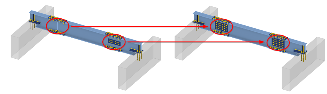
Cleat, Splice, Fin plate, and Stiffening plate operations are unified across the IDEA StatiCa Connection and Member applications in order to produce identical designs, which offers great flexibility and control over complex Member models.
The mapping of constraint points and the selection of plates in Cleat, Splice, Fin plate, and Stiffening plate manufacturing operations are consistent in the project data of all applications dealing with steel connections.
This prevents situations when in the Member app, a cut operation (utilizing cut by a plate, workplane of negative volume) is applied in one connection node of the analyzed member, causing discrepancies in the operations in other connection nodes of this member.
A parent-child relationship between plates and members is ensured even after one part of the Member model is touched by modifying the number of edges of plates and their ordering. This methodology ensures that even if the parent plate is removed, the subsequent operations can accurately reference the correct plate based on this relationship, maintaining the intended positioning designed in the Connection application.
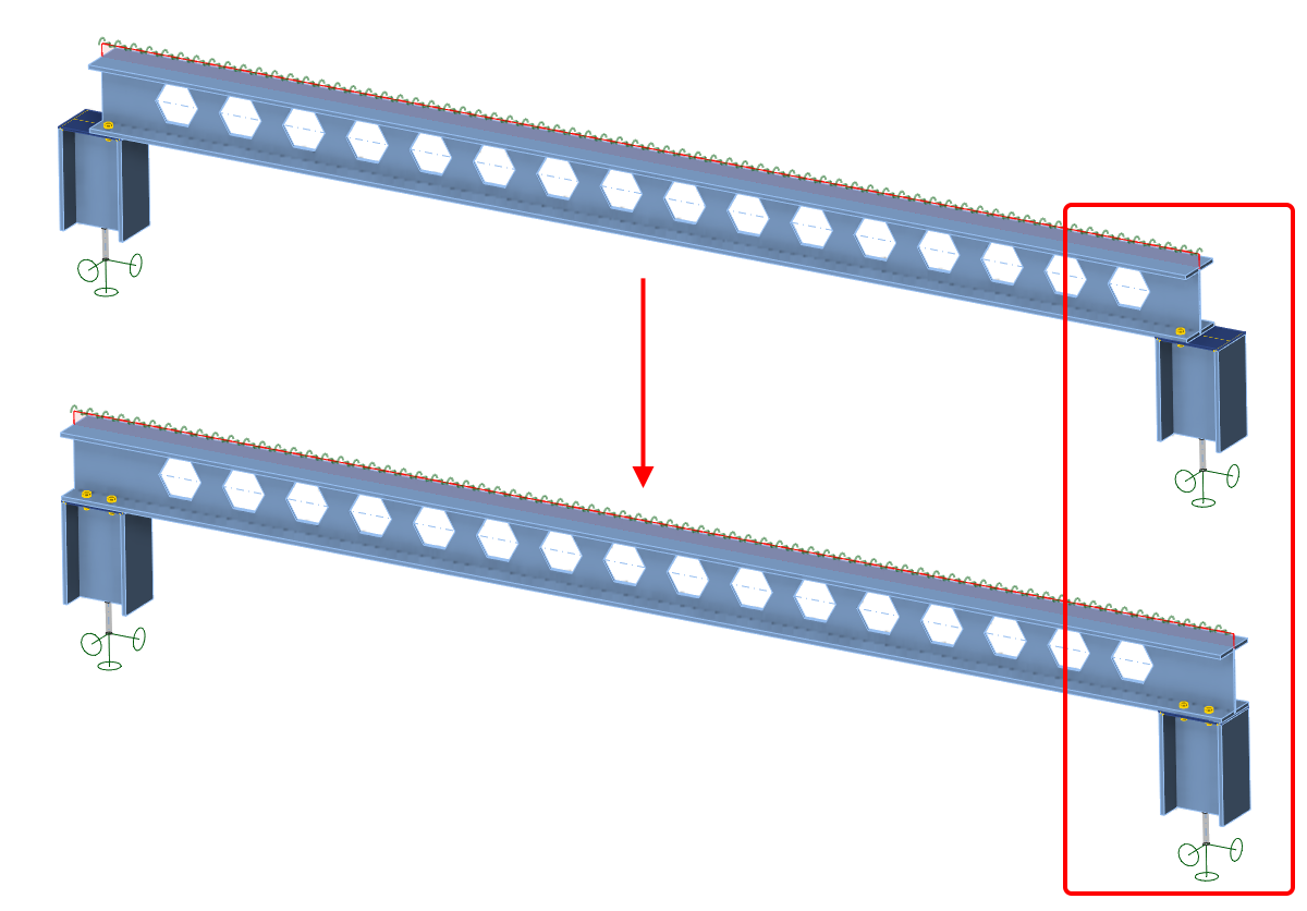
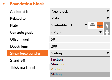
Sliding option for a concrete foundation block
Having the option of shear force transfer for a foundation concrete block enables the simulation of a sliding hinge support model in a Member project.
When modeling a simply supported beam in IDEA StatiCa Member, you can use this option for defining the roller (sliding hinge). This option keeps the "close-to-zero" bending moment at the ends of the beam supported by a concrete block.
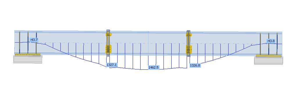
From Member, open the connection at one end of the beam. Define the anchoring/foundation concrete block and switch the Shear force transfer option to Sliding. Also, remove all the anchors in the Editor.
Please note that the other side of the beam must stay active to transfer forces in both directions so that the static system remains determined.
Although this setting also works in Connection, it is specifically designed to be used in IDEA StatiCa Member.