Hegesztések szabványellenőrzése (EN)
A sarokvarratokat az EN 1993-1-8 szerint ellenőrzik. A tompahegesztések szilárdsága megegyezik az alapanyagéval, ezért azokat nem ellenőrzik.
Sarokvarratok
Méretezési ellenállás
A varratokban alkalmazott képlékeny átcsoportosítás automatikusan elkerüli a feszültség-szingularitásokat a varratelemekben, és a feszültséget a varrathossz mentén tovább osztja el. A varratok szilárdsága közelítőleg megegyezik a kézi számítással kapott értékkel, és a feszültség helyesen oszlik el bonyolult esetekben is, például merevítetlen övhöz való hegesztésnél (EN 1993-1-8 – 4.10. pont). A sarokvarratok torokkeresztmetszetében ébredő feszültséget az EN 1993-1-8 4.5.3. pontja szerint határozzák meg. A feszültségeket a varratelemek feszültségeiből számítják. A hosszirányú varrattengelyre ható hajlítónyomatékot nem veszik figyelembe.
\[ \sigma_{w,Ed}=\sqrt{\sigma_{\perp}^2 + 3 \left ( \tau_{\perp}^2 + \tau_{\parallel}^2 \right )} \]
\[ \sigma_{w,Rd} = \frac{f_u}{\beta_w \gamma_{M2}} \]
Varratkihasználtság
\[ U_t = \max \left\{ \frac{\sigma_{{w,Ed}}}{\sigma_{w,Rd}}, \frac{\sigma_{\perp}}{0.9 f_u / {\gamma_{M2}}} \right\} \]
ahol:
- σw,Ed – egyenértékű feszültség a varratban
- σw,Rd – varratellenállás
- βw – korrelációs tényező (EN 1993-1-8 – 4.1. táblázat)
- fu – szakítószilárdság, a két csatlakoztatott alapanyag közül a kisebb értékű, vagy a felhasználó által választott anyag szerint
- γM2 – biztonsági tényező (EN 1993-1-8 – 2.1. táblázat; a Szabványbeállításokban szerkeszthető)
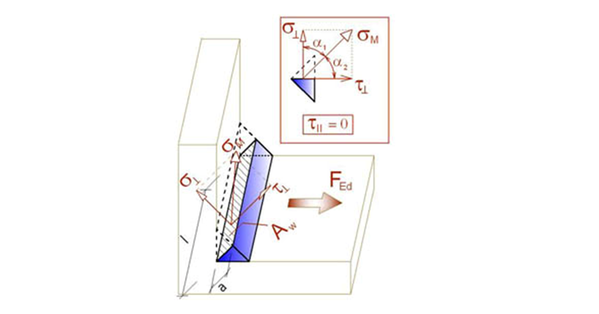
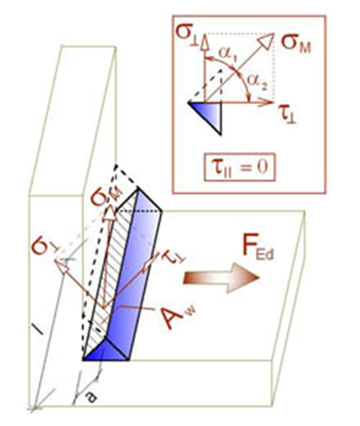
- σ┴, τ┴, τ‖ – feszültségek a varratban az alábbi ábra szerint:
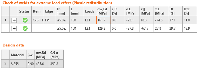
Az ellenőrzéshez szükséges összes érték táblázatokban jelenik meg. Az Ut a legjobban igénybevett elem kihasználtságát jelenti. Mivel a varratfeszültségének képlékeny átcsoportosítását alkalmazzák, ez a mérvadó kihasználtság. Az Utc a kihasználtságról nyújt tájékoztatást a varrathossz mentén. Ez a tényleges feszültség aránya a varratelemek összes elemén a teljes varrathossz feszültségének méretezési ellenállásához képest.
A varrat egyenértékű feszültség diagramja a következő feszültséget mutatja:
\[ \sigma = \max \left \{ \frac{\sigma_{\perp}}{0.9 \beta_w}, \, \sqrt{\sigma_{\perp}^2 + 3 \tau_{\perp}^2 + 3 \tau_{\parallel}^2} \right \} \]
Tompavarratok
A varratok tompahegesztésként is megadhatók. A tompahegesztéseknél teljes kötési behatolást feltételeznek, ezért az ilyen varratokat nem ellenőrzik.
Elrendezési szabályok
A hegesztett kapcsolatok minimális lemezvastagságát az EN 1993-1-8 – 4.1(1) szerint ellenőrzik:
- Üreges acélszelvény esetén a lemezvastagság legalább 2,5 mm legyen
- Egyéb lemezek esetén a lemezvastagság legalább 4 mm legyen
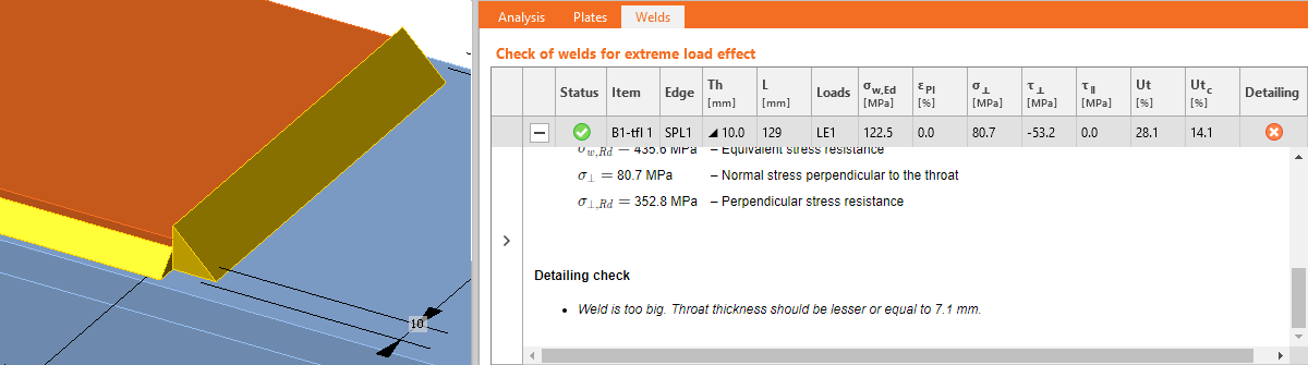
A sarokvarratok maximális varrattorokvastagságát párhuzamos lemezek esetén ellenőrzik. Hibát jeleznek, ha az ilyen varratok geometriai kényszerfeltételek miatt nem kivitelezhetők.
A sarokvarratok minimális varrattorokvastagsága az EN 1993-1-8 – 4.5.2(2) szerint legalább 3 mm legyen. Ha ez a követelmény nem teljesül, hibát jeleznek.
Figyelmeztetést adnak, ha a varrattorokvastagság kisebb, mint a DIN EN 1993-1-8 – NA to 4.5.2 szerinti követelmény:
\[a \le \sqrt{t_{max}}-0.5\]
ahol:
- \(a\) – varrattorokvastagság
- \(t_{max}\) – a vastagabb csatlakoztatott lemez vastagsága
- az egységek [mm]-ben értendők
Tájékoztatást adnak, ha a varrattorokvastagság kisebb, mint a FprEN 1993-1-8:2023 – 6.9(4) szerinti hegesztett kötések minimális képlékenységére vonatkozó követelmény. Ezt a követelményt kétoldalas sarokvarratok esetén a következőképpen ellenőrzik:
\[a/t=\frac{\beta_w\gamma_{M2} f_y}{\sqrt{2} f_u \gamma_{M0} } \cdot \min \left \{1.0, 1.1\frac{f_y}{f_u} \right \}\]
ahol:
- \(a\) – varrattorokvastagság
- \(t\) – az éllel csatlakoztatott lemez vastagsága
- \(\beta_w\) – varrat korrelációs tényező
- \(\gamma_{M2}\) – biztonsági tényező csavarokhoz és varratokhoz; a Szabványbeállításokban szerkeszthető
- \(f_y\) – lemez folyáshatára
- \(f_u\) – varrат szakítószilárdsága
- \(\gamma_{M0}\) – biztonsági tényező lemezekhez; a Szabványbeállításokban szerkeszthető
Az egyoldalas sarokvarratok varrattorokvastagsága kétszer akkora, mint a kétoldalas sarokvarratoké.