Strengthening of longitudinal bracing
Longitudinal bracing is a reliable and widely used element in steel hall structures. Thanks to the accurate calculations provided by IDEA StatiCa Member's simulation, engineers can now reduce their estimates of buckling length and account for the effect of eccentric connections on the overall bracing behavior.
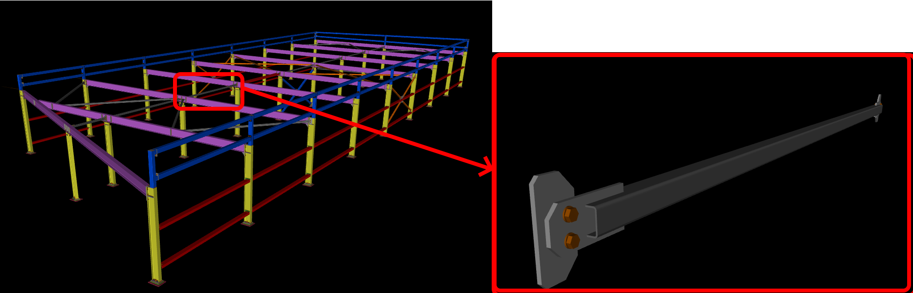
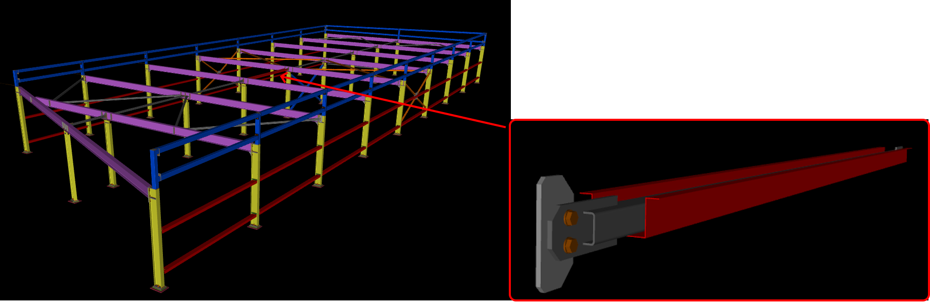
Basic information about the structure
The hall is 8.3 meters wide, 22.6 meters long, and 2.3 meters high. The critical member for analysis is a 50x50x3 mm SHS profile welded to IPE 180 on an eccentric gusset plate.
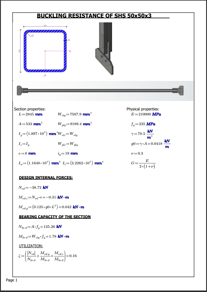
Hand-calculation - axial and bending resistance
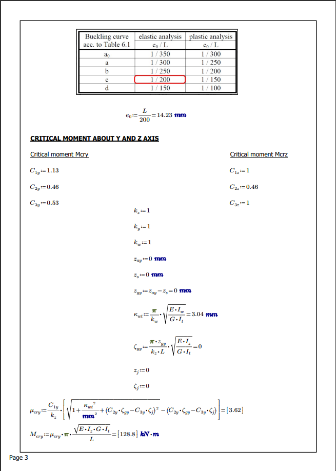
To conduct advanced analysis, it's crucial to hand-calculate and comprehend the critical member's behavior. The hand calculation is performed by using EN-1993-1-1. In the calculation, the design axial force and bending moments caused by the eccentricity of the gusset plate and self-weight are considered. The self-weight has a minor effect on the code-check and utilization. This load case will be neglected for the FEA approach.
Hand calculation - axial and bending resistance
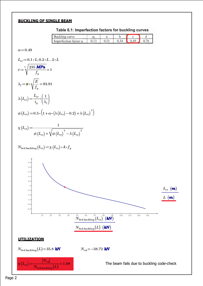
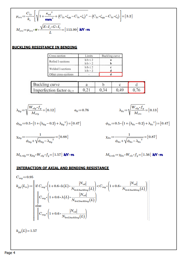
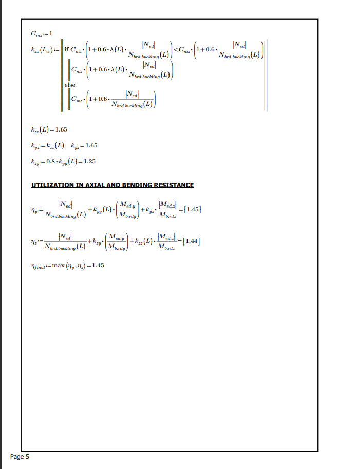
Based on the hand-calculation approach, it is obvious that the member stability check under combined compression and bending failed. The utilization is 145%.
Imperfections of hand calculation:
- The calculation assumptions consider pin connections and don't consider the connections' real stiffness.
- The critical length estimation is based on the connections' arrangements without considering the actual stiffness.
- There is no visual representation of the model's behavior. You have to blindly trust the equation, mainly the coefficient that you input.
- The critical spot on the structure may be overlooked due to the assumptions we introduce.
- Incorrect initial assumptions of inexperienced(young) engineers can lead to fatal errors.
- The determination of some coefficients in the design code approach is complicated in some cases, mainly for Cmy, Cmz, and CmLT coefficients.
Unstrengthened model
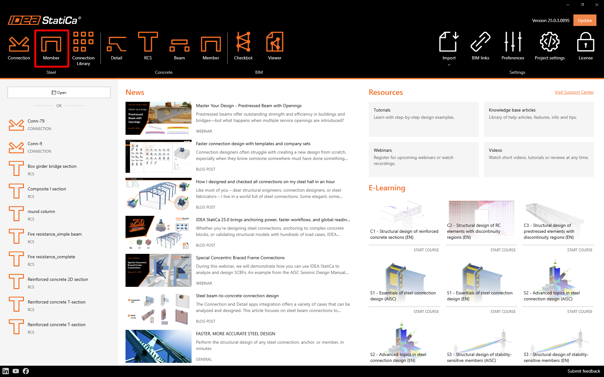
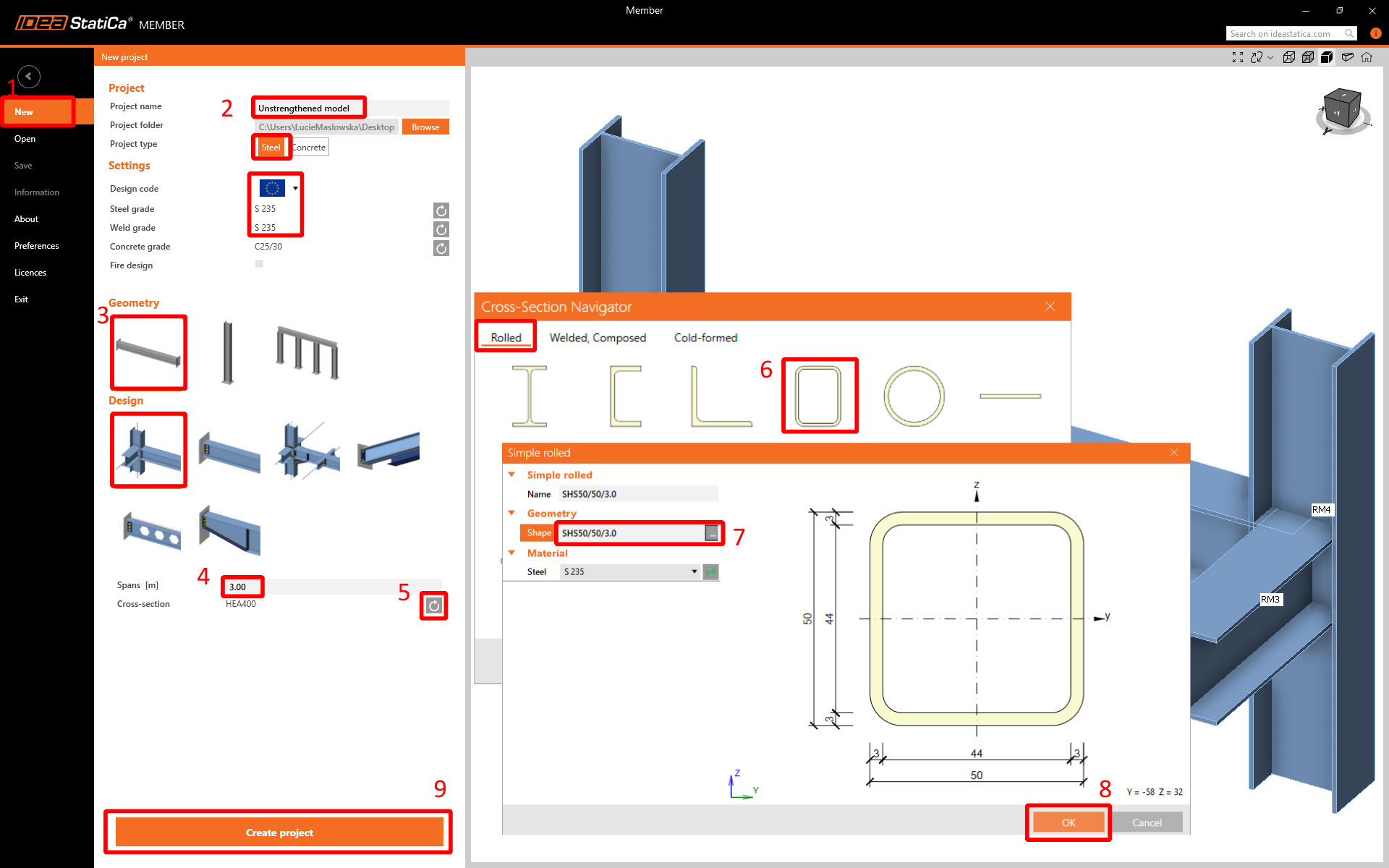
New project
Launch IDEA StatiCa-->Steel-->Member.
Please follow the required steps to create a basic model that can be further adjusted and improved.
Design
Rigid support member
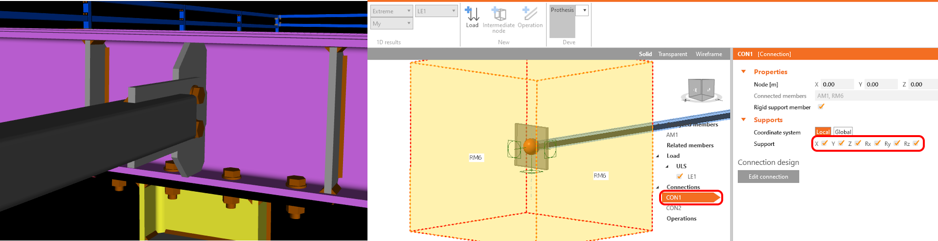
To enable a Rigid support member, simply select CON1 and CON2, then select the checkbox in the property grid.
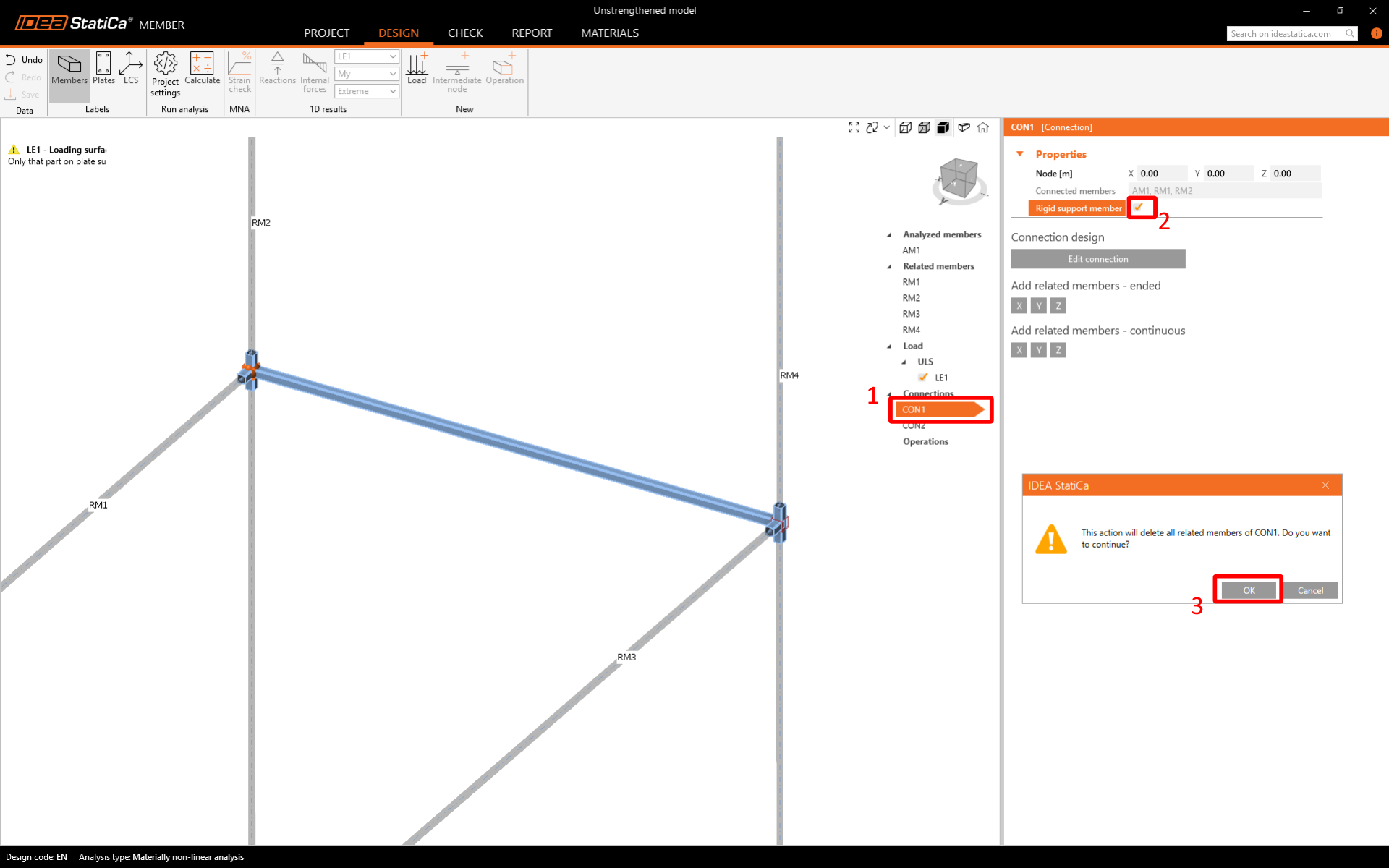
You can observe how the Rigid support member is displayed in the scene. The next step is to remove all loads from the model.
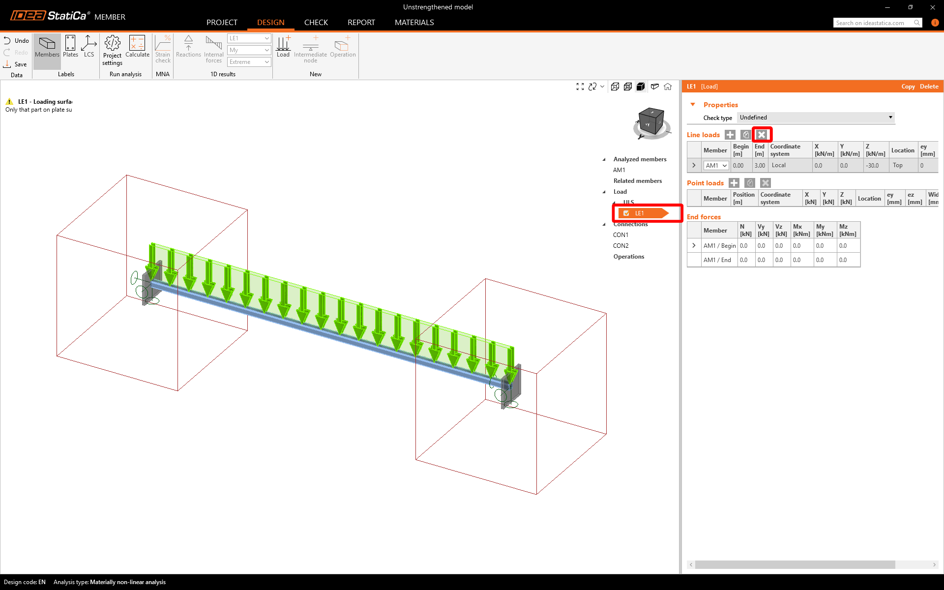
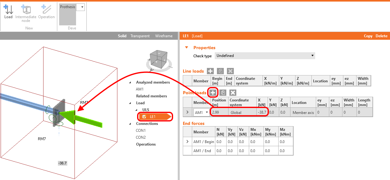
Load
The longitudinal bracing is loaded axially. The design compressed force of -38.7 kN is related to the end of the analyzed member.
The self-weight of the structure has a minor effect on the behavior due to the low weight of the element. This load is neglected.
Boundary condition
The gusset plate is welded to IPE 180. To simulate a similar boundary condition, make sure you select that all six degrees of freedom are restrained for CON1.
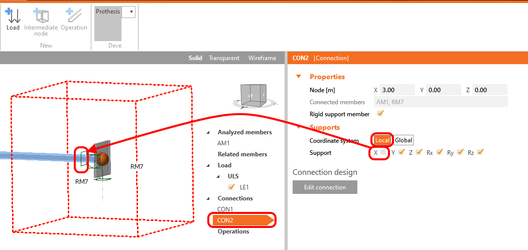
Release the support in the local X-direction for CON2 due to the axial load predefined in the Load tab.
Connection
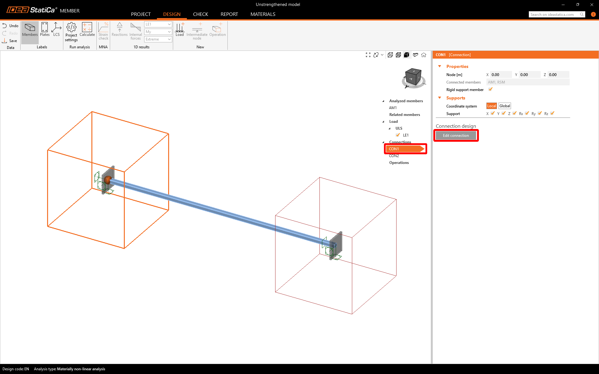
Now is time to create the connections. Just choose the CON1 and Edit connection.
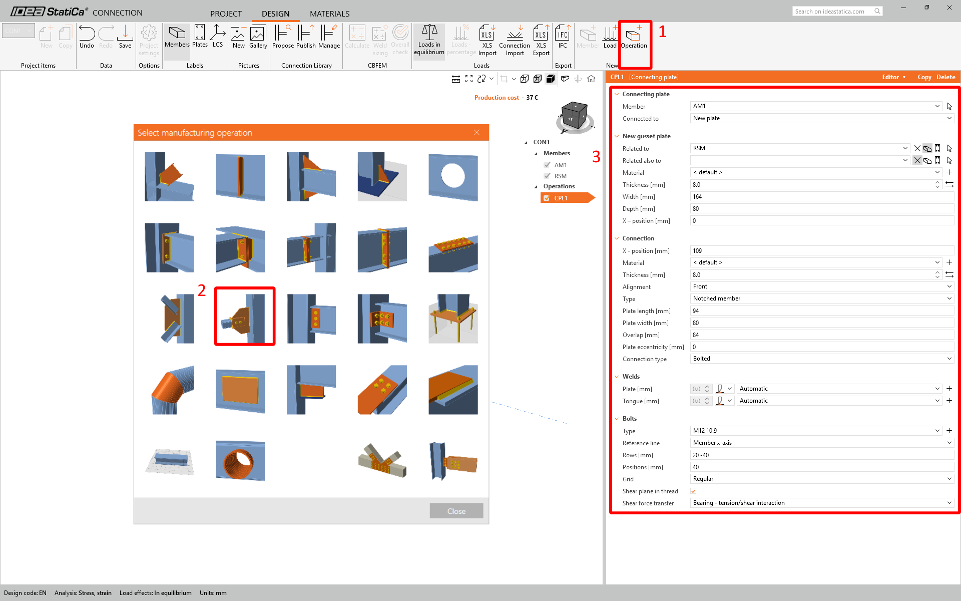
Edit CON1 and create the connection. Select the manufacturing operation Connecting plate and set the parameters.
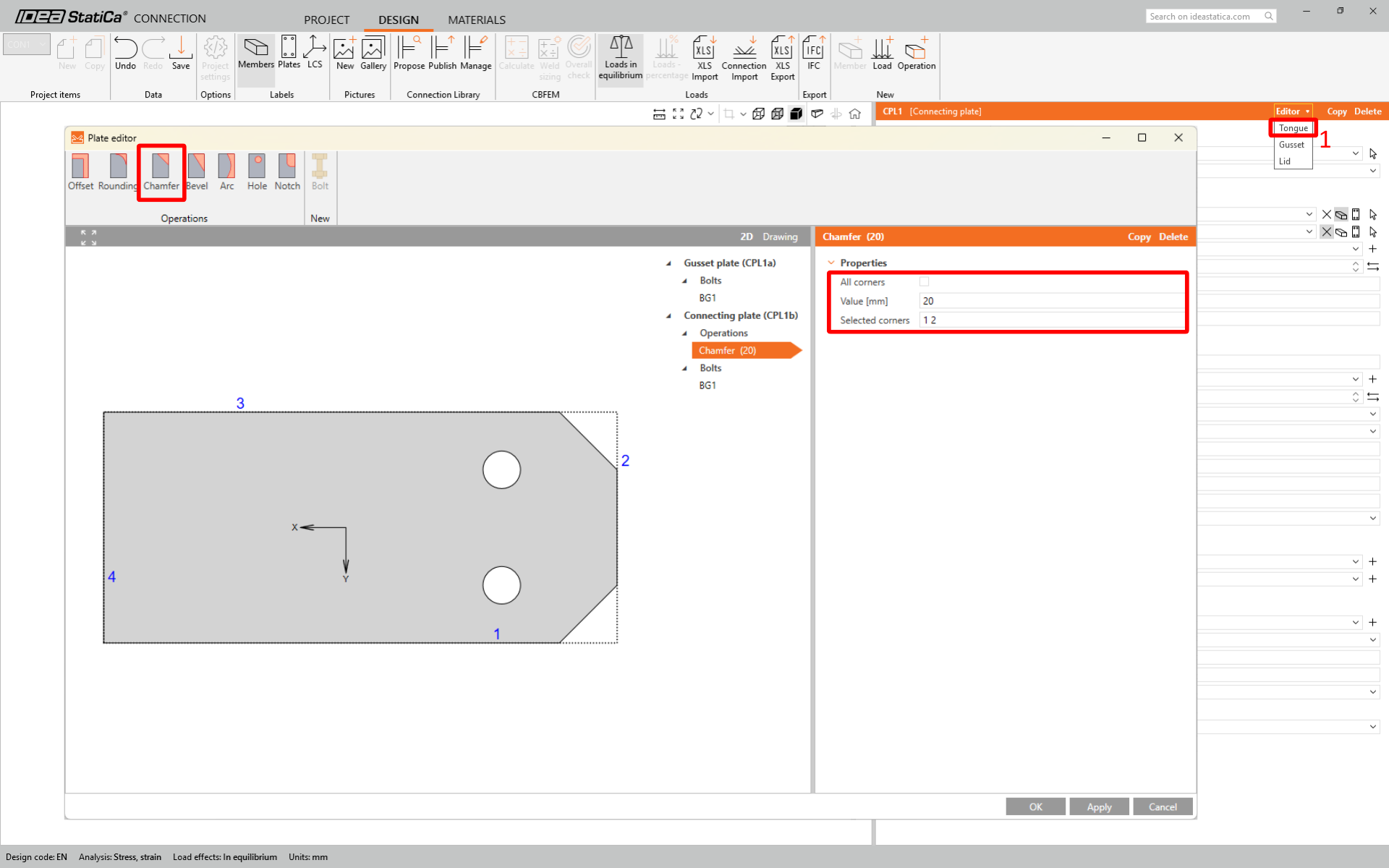
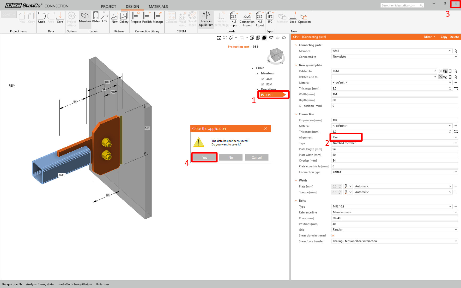
IDEA StatiCa Connection window will open in a few seconds. Build the connection step by step by adding the required operation. Add the manufacturing operation Connecting plate CPL1 and set its parameters as shown in the figure below.
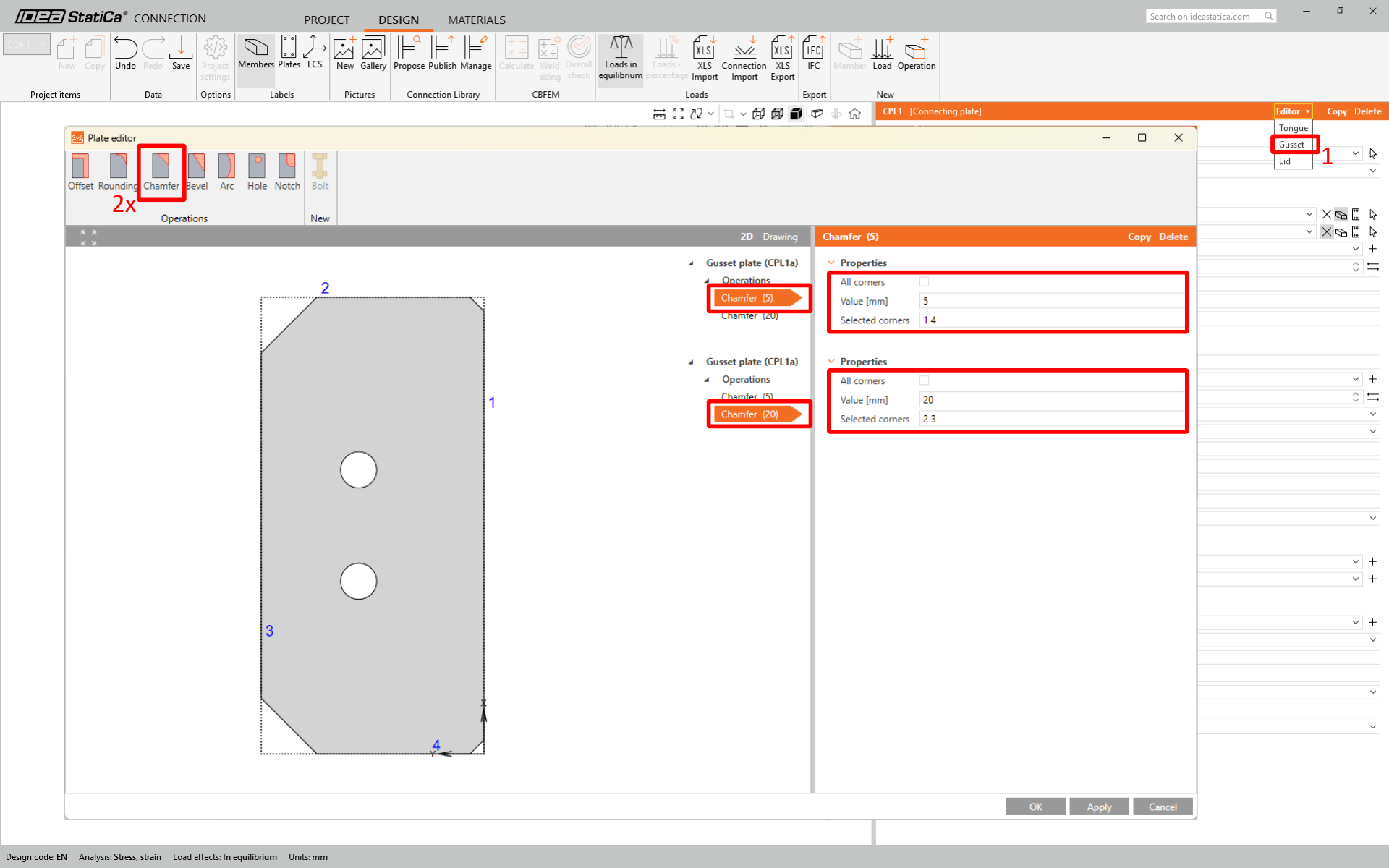
In the next step adjust geometry of tongue and gusset plate in plate editor.
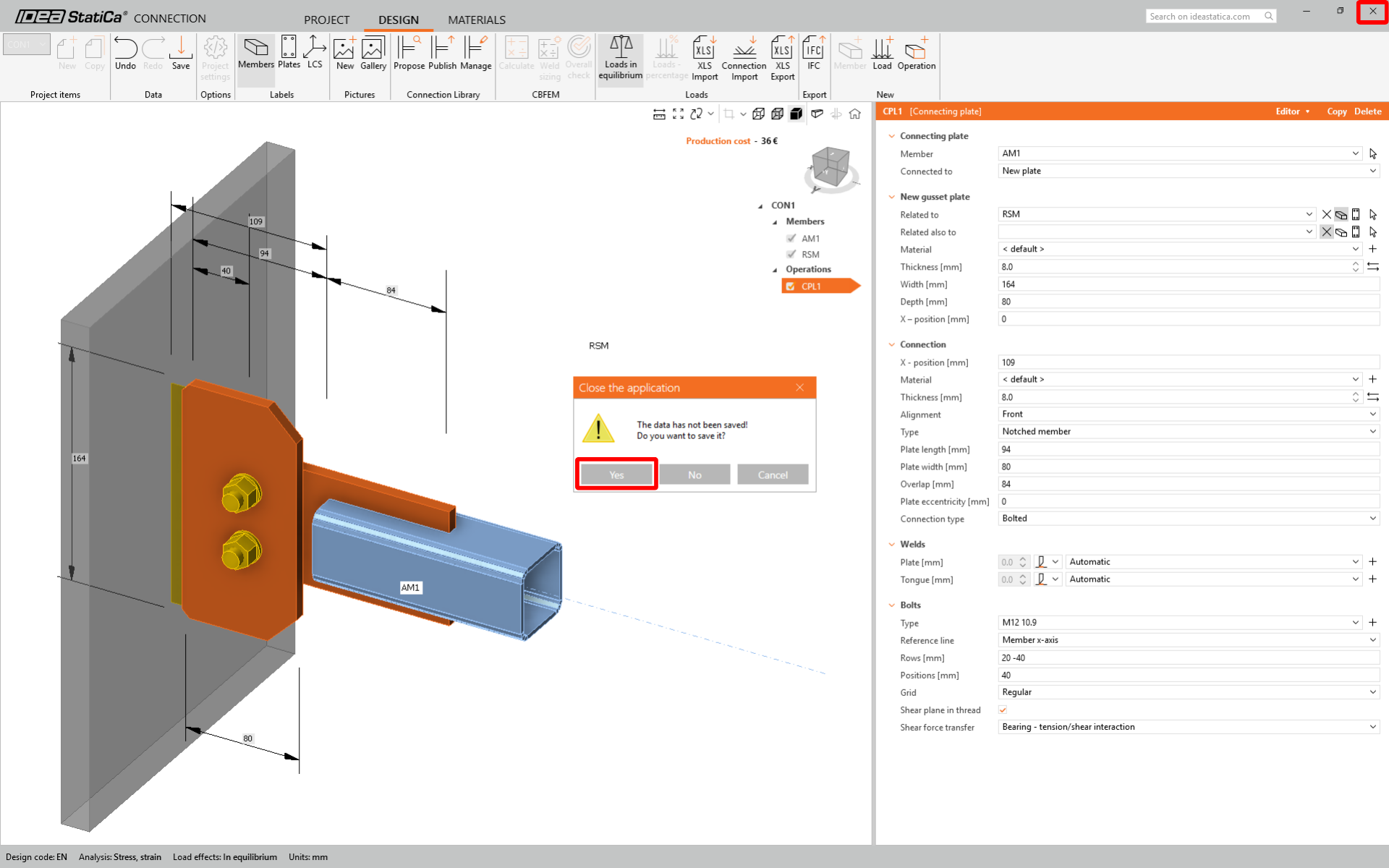
Now, you can close and save CON1.
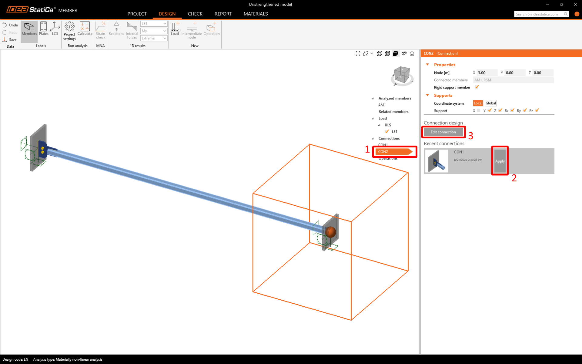
The CON1 is set. Now click on CON2 and by using the feature Recent connection apply the same connection to CON2 and open the connection in IDEA StatiCa Connection.
Change Alignment to Rear due to the reverse eccentricity of the gusset plate in the CON2 joint.
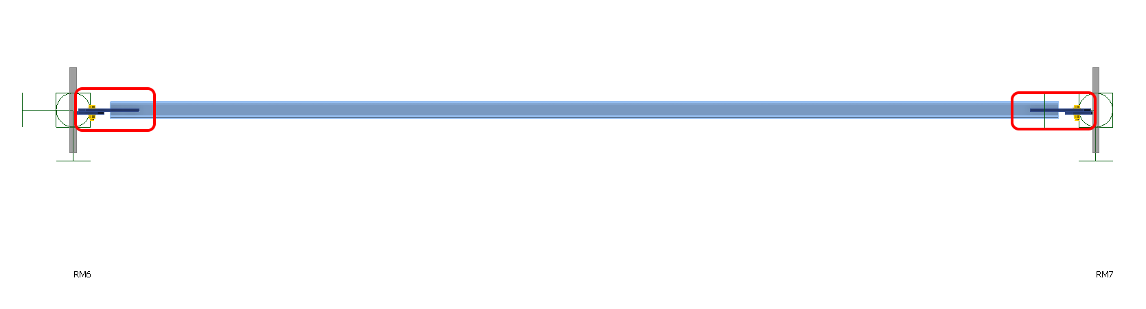
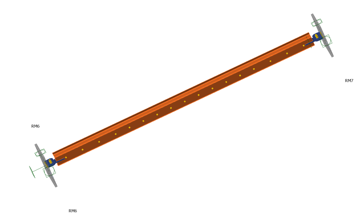
The top view of the final model will now look like this:
Check
Material Nonlinear Analysis
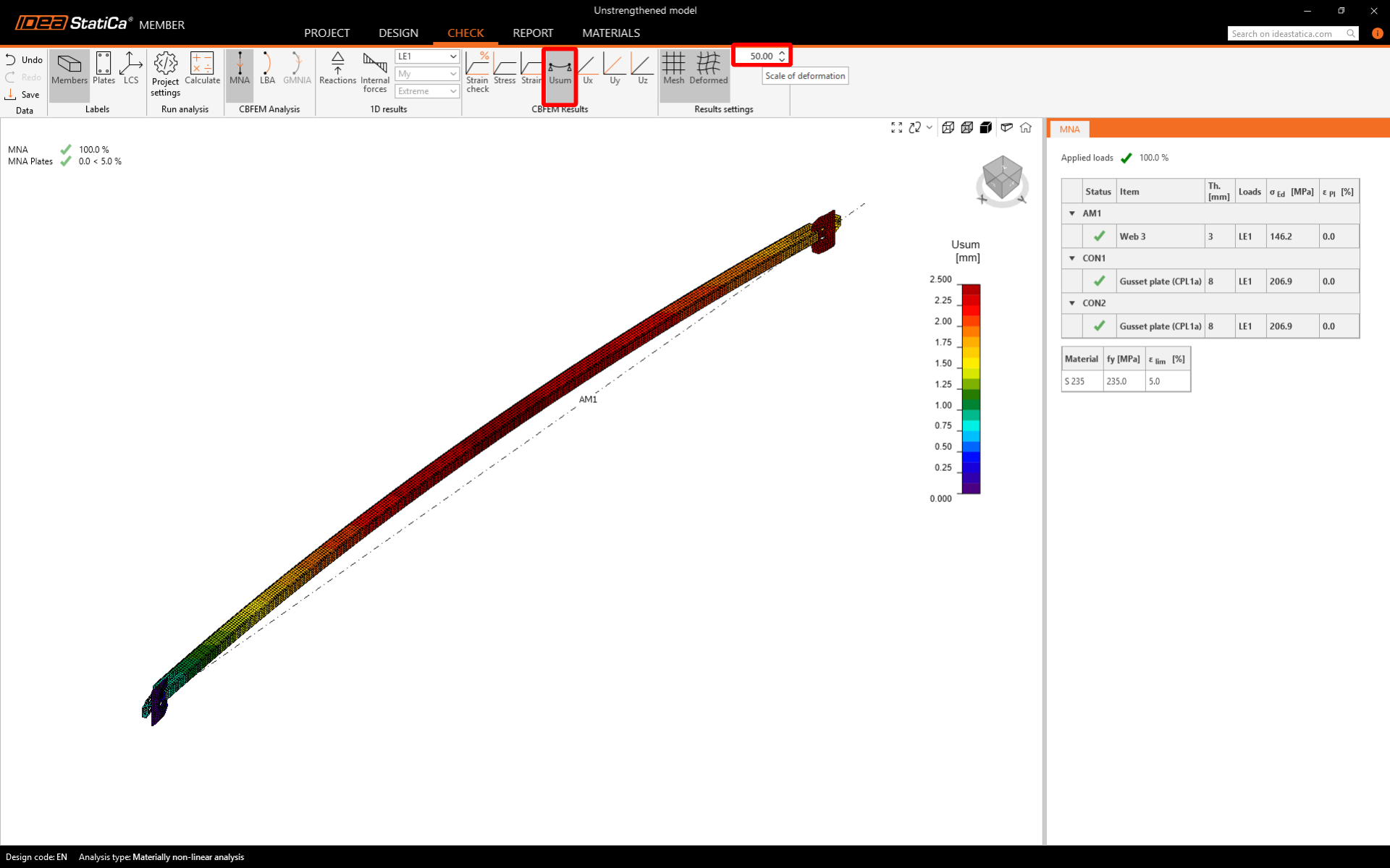
Material Nonlinear Analysis (MNA) takes into account material plasticity and provides valuable insights into the model's equivalent stress and plastic strain. This analysis doesn't focus on code-checks of bolts and welds as these would have to be checked in the separate Connection model.
Switch to the Check tab and run the MNA.
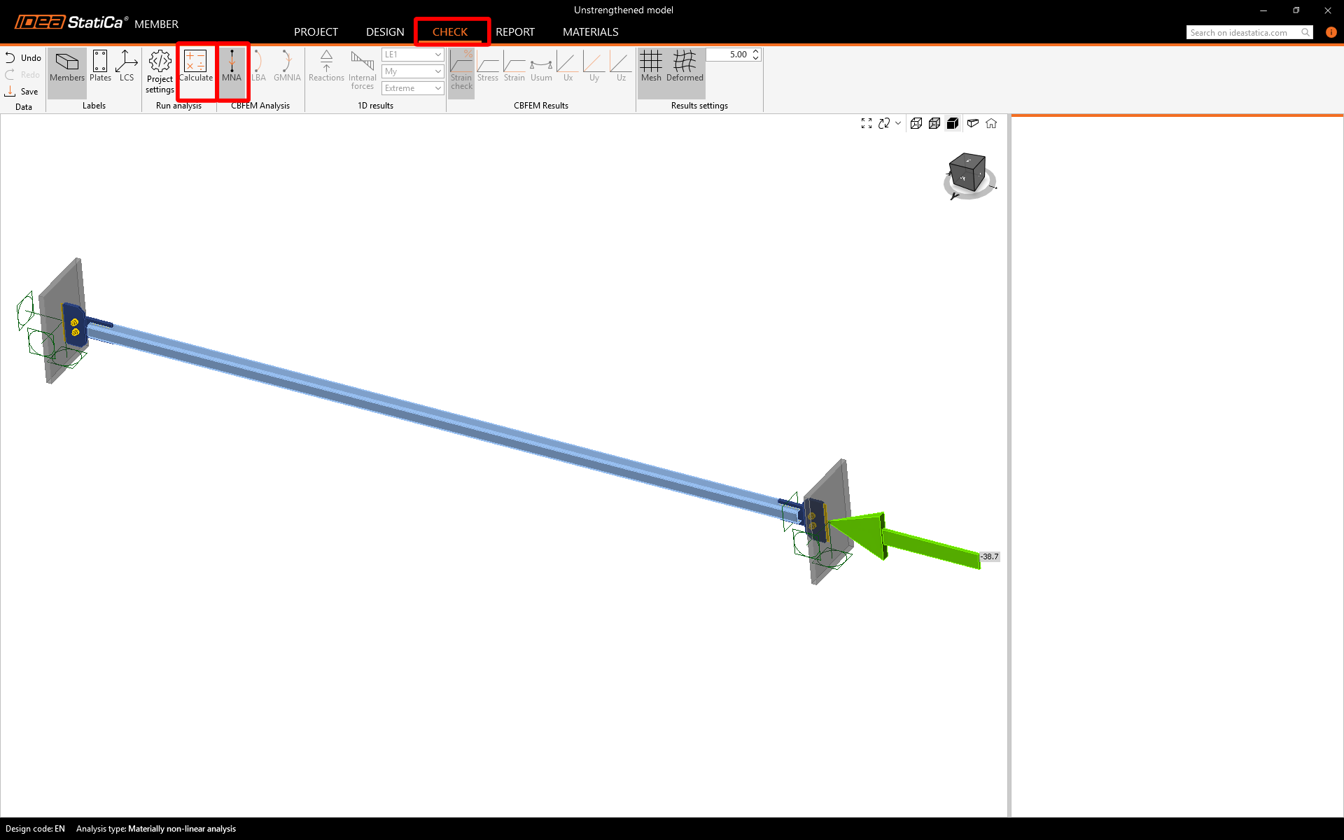
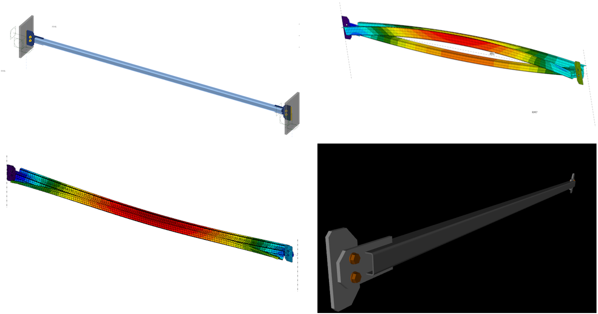
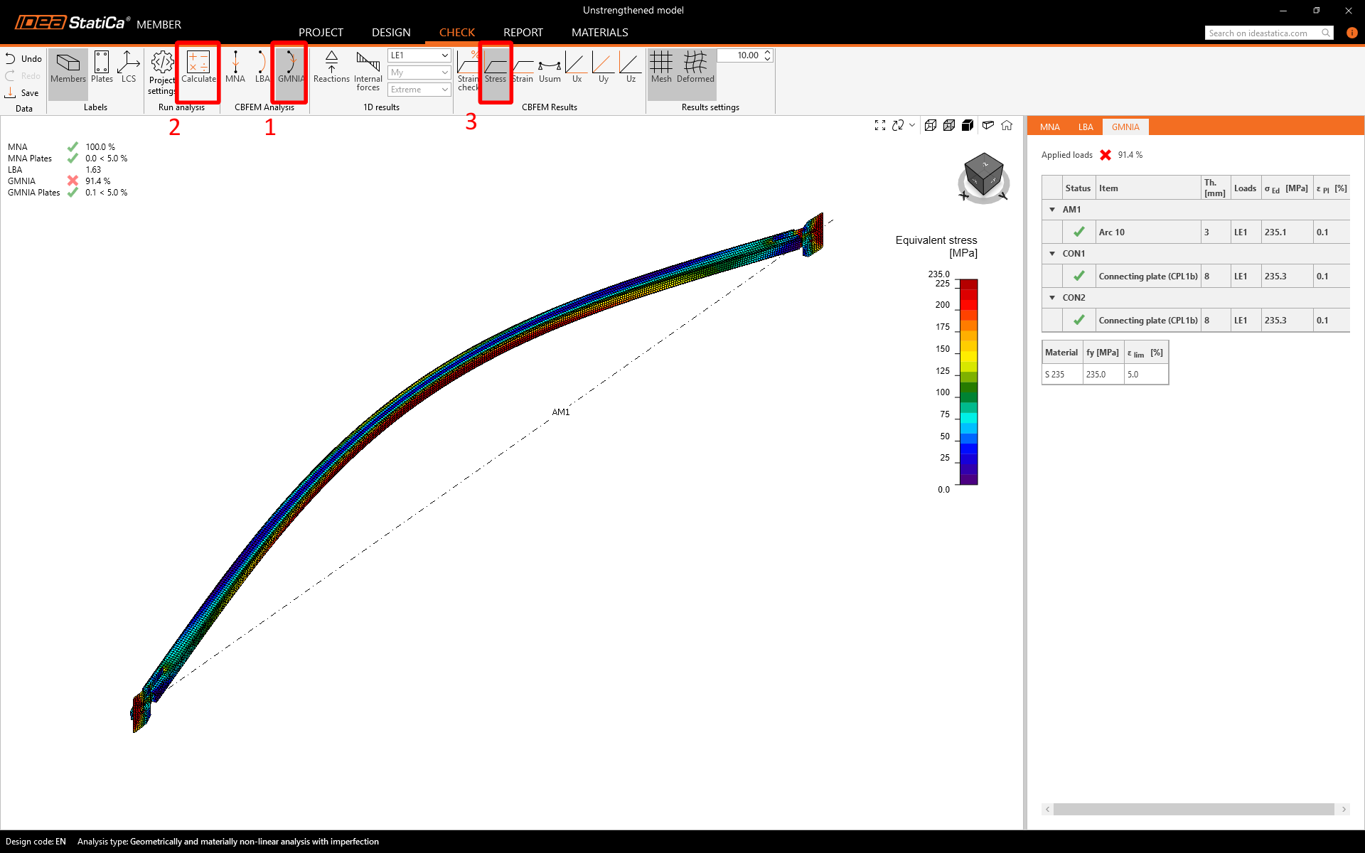
You can turn on Equivalent stress and check the field output on the whole member. The stress-critical point is detected on the connection itself.
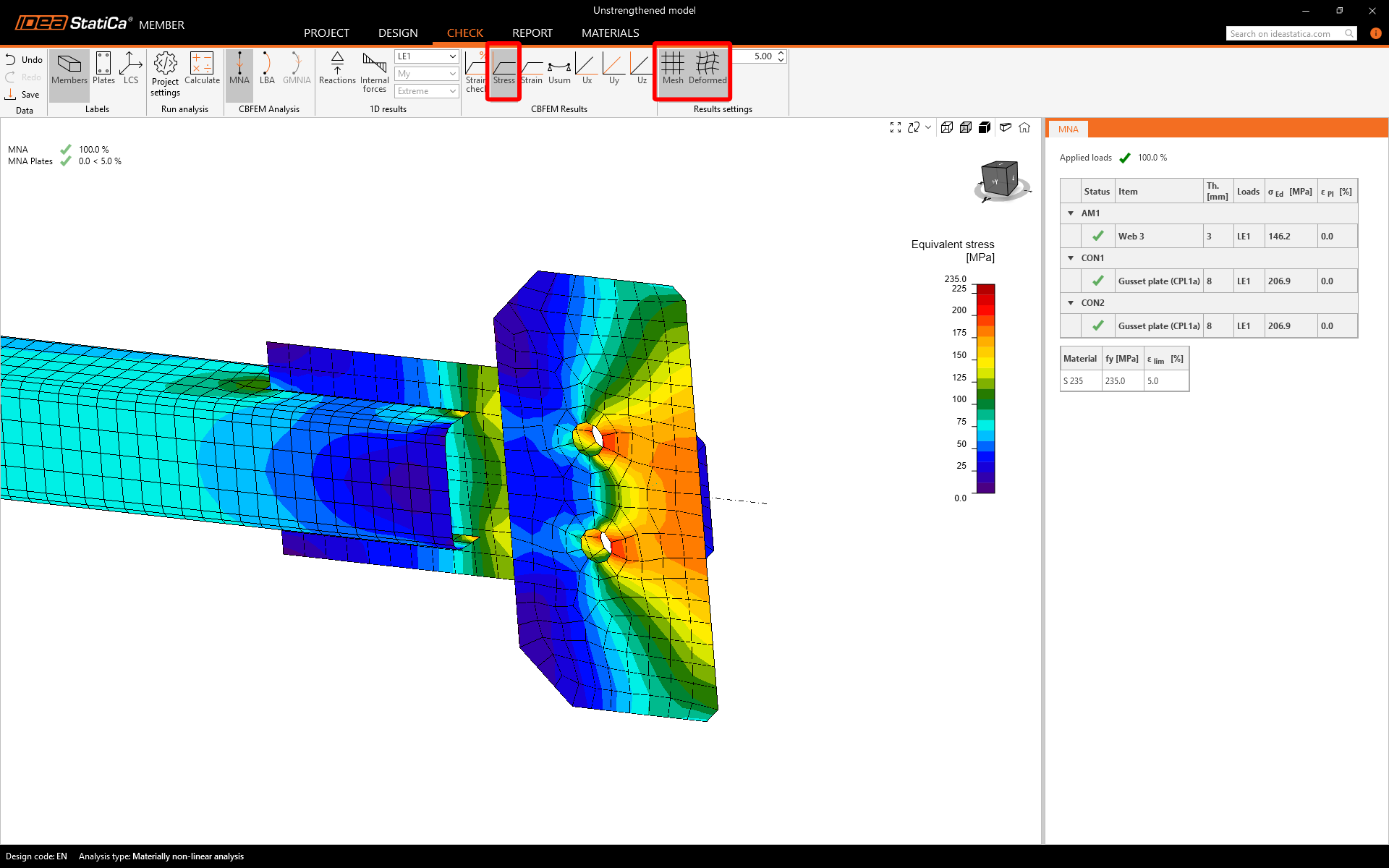
The deformations indicate bending caused by the eccentricities of connections on both sides and additional stresses.
Linear Buckling Analysis
Buckling analysis is an invaluable tool for anticipating structure failure under compressive loads. It assesses stability and predicts the critical load capacity before buckling or collapse. This method is essential for ensuring structural integrity and safety.
The output from the analysis:
- Critical alfa factor
- Buckling shapes
The Linear Buckling Analysis (LBA) provides several crucial outputs. The first buckling shape shows a low loss of stability by a factor of 1.63 x Ned. However, the second mode shape, due to a symmetrical cross-section orthogonal, reaches a higher factor of 1.90. It's important to keep in mind the mutual interaction of the modes in the upcoming analysis.
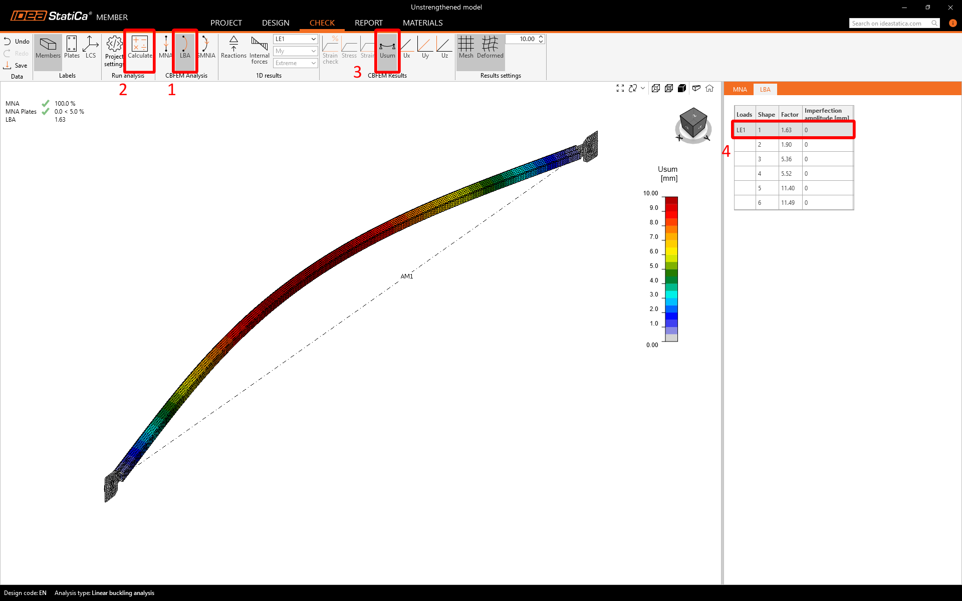
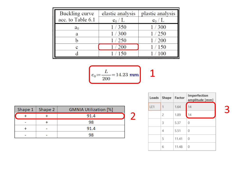
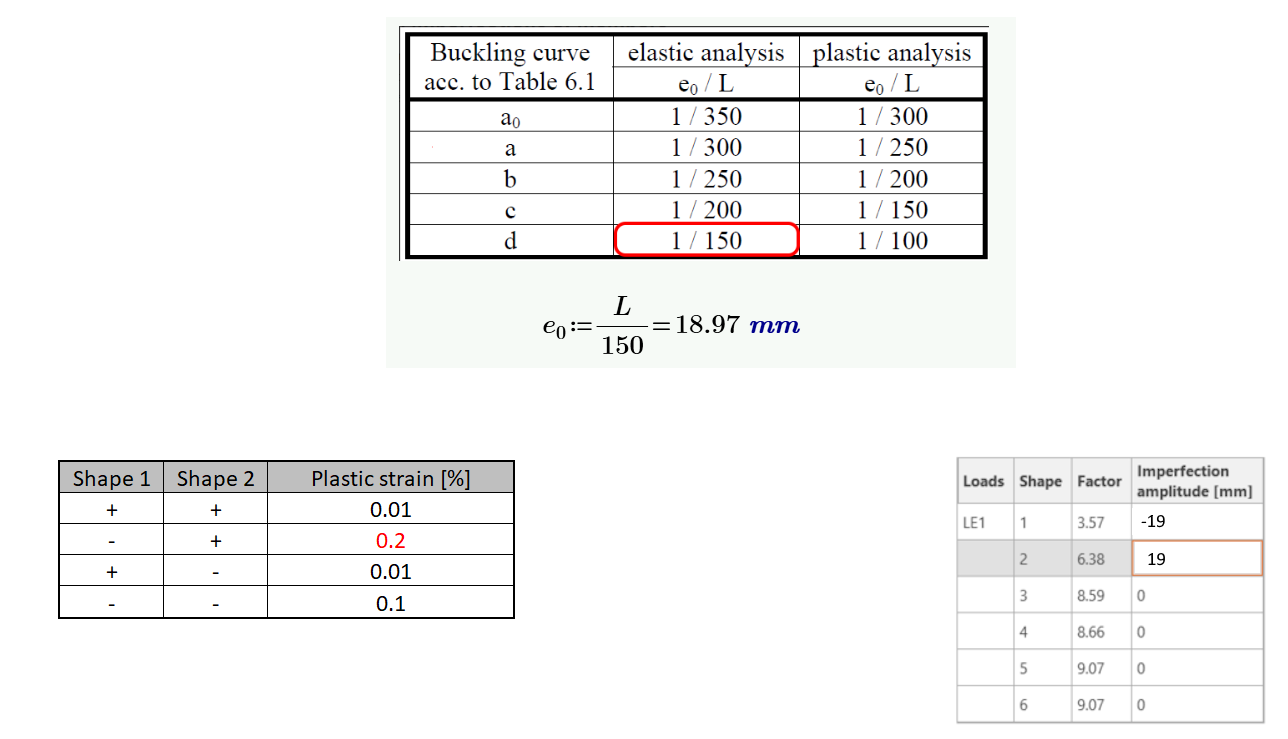
To get started with Geometric and Material Nonlinear Analysis with Imperfection (GMNIA), the initial state should be set as the local imperfection. Following EN 1993-1-1, Cl. 5.3.2 (3), the local imperfection must be carefully chosen. Before inputting the imperfections, a permutation of options with varying signs is necessary to select the critical ones (2). Only the imperfections that indicate critical utilization should be used for the final analysis (3). It's important to be meticulous when selecting the imperfections to ensure an accurate and reliable analysis.
Geometrical and Material Nonlinear Analysis with Imperfection
GMNIA is a type of analysis used in engineering to study the behavior of structures under extreme loads. This analysis takes into account both the geometric nonlinearity (changes in shape) and material nonlinearity (changes in material properties) of a structure, as well as any initial imperfections or deformations present in the structure. By considering these factors, engineers can understand better how a structure will behave under loading and make informed decisions about its design and safety.
The analysis seeks equilibrium in every increment using the initial deformed shape from LBA's imperfection. If equilibrium cannot be found, the solution stops.
- Material nonlinearity occurs when the material can no longer deform elastically and begins to yield plastically, causing a change in its behavior.
- Stability issues arise when the structure is unable to undergo further iterations due to a lack of equilibrium and a bifurcation point has been reached.
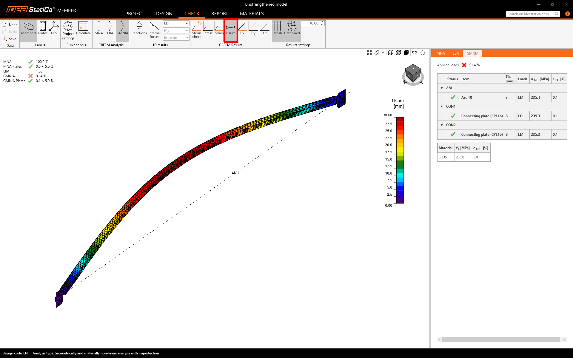
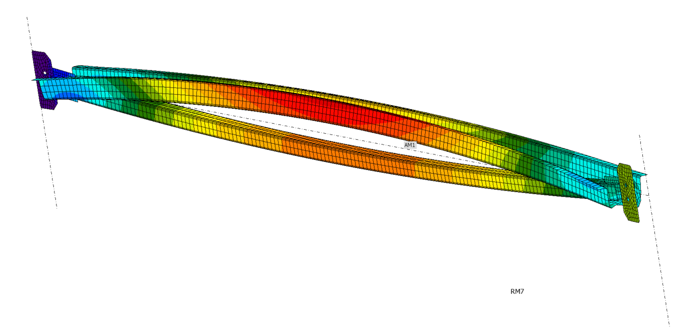
Run the GMNIA. The results prove that the beam has lost stability. The calculation stopped instead of the plasticity potential being reached.
Deformations
Conclusion for the unstrengthened part
The analysis results confirm the initial assumptions made during the hand calculation. The hand calculation shows that utilization is at 145%, which is a bit high. However, the calculation was stopped at 91.4% by GMNIA due to a stability problem. It's worth noting that the plasticity potential was not reached. When compared to our assumptions, GMNIA's utilization value is at 1/0,914 = 109%.
To ensure stability, it is recommended to strengthen the model. Due to the difficulty of replacing members in the current hall, the focus will be on strengthening them. IDEA StatiCa Member will cover the process of strengthening the members.
Model with strengthening
The existing cross-section will be reinforced using another section coupled using the bolts.
Copy of the existing project
The easiest way to begin is by duplicating the current model, including all pre-established materials, manufacturing processes, and static layouts.

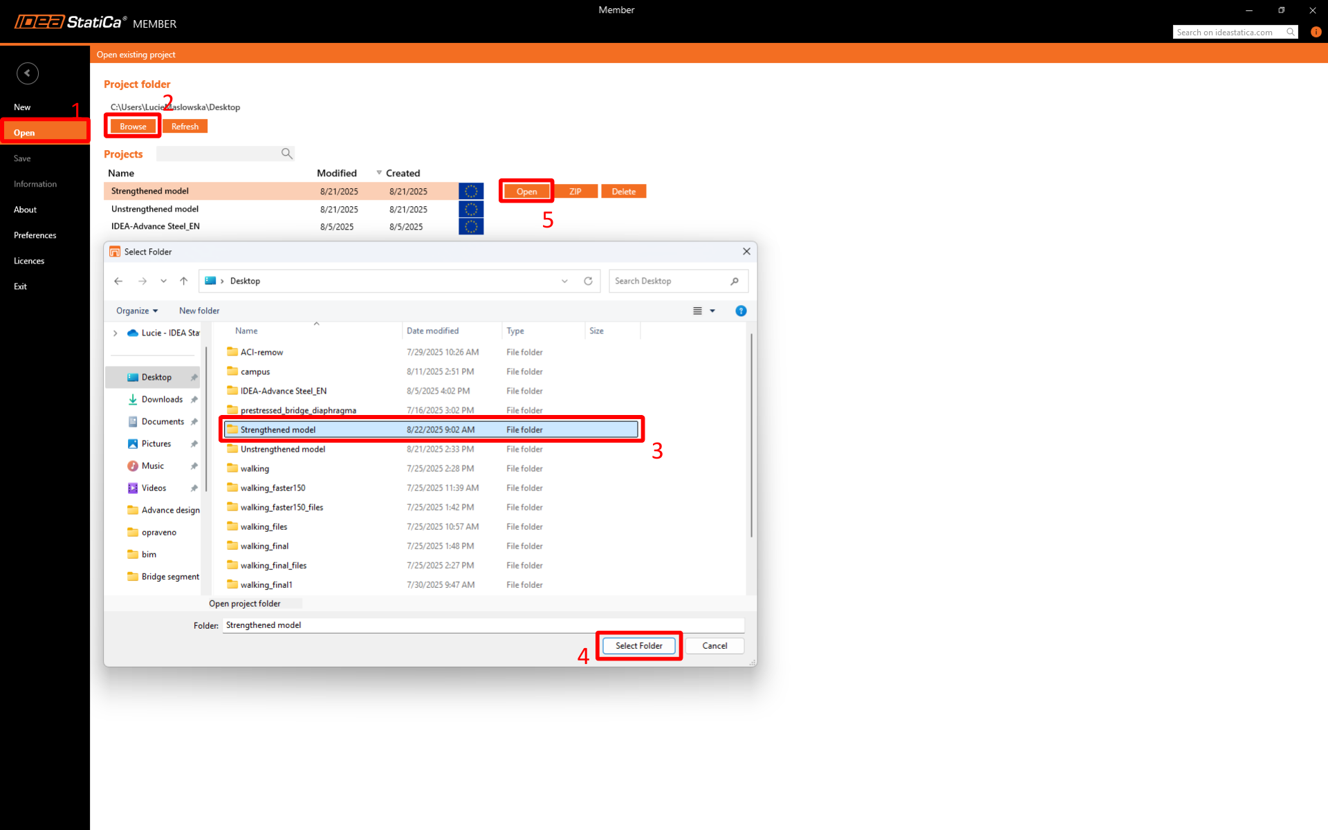
New project
Launch IDEA StatiCa-->Steel-->Member and Open the model that was copied.
Design
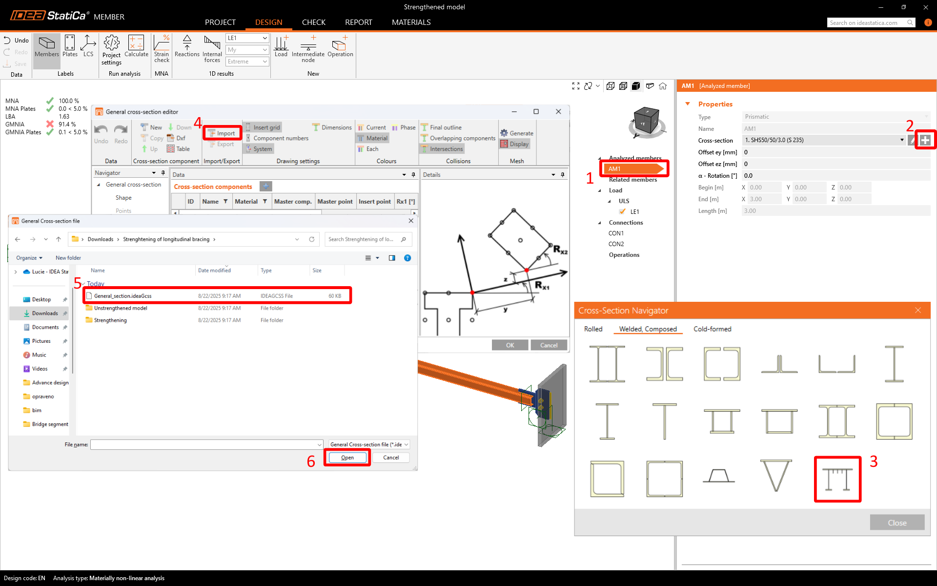
Modify the analyzed member AM1(1). Define New Section(2)-->go to the General Section Designer(3)
-->Import the predefined section (4)-->Select the General_Section.ideaGcss(5).
This is the template of the predefined general section. The original section has been reinforced using the CFomega section.
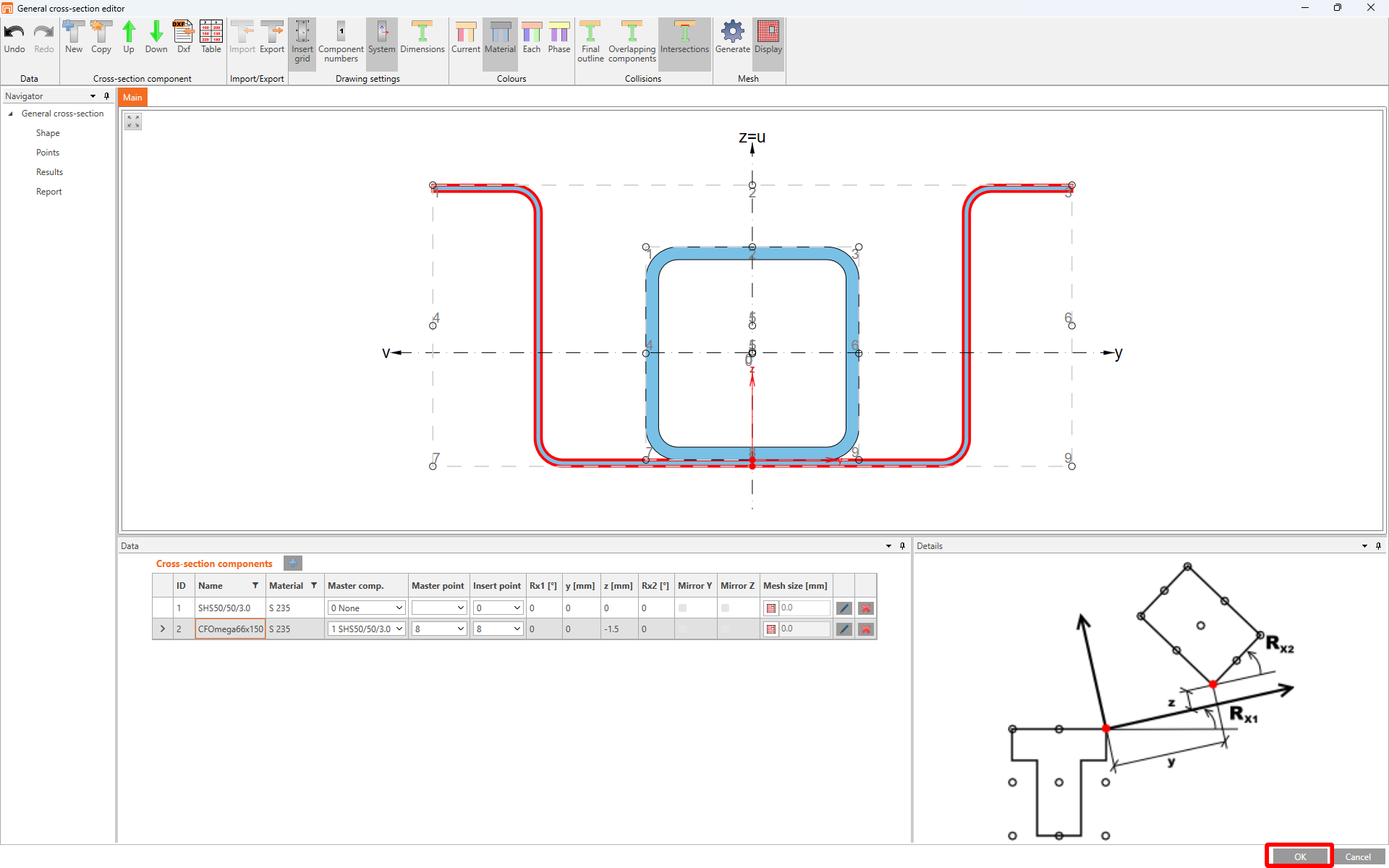
The model below shows the created structure. However, a crucial warning is that the member comprises cold-formed sections that cannot be welded, meaning that the section cannot be coupled and the integrity is not guaranteed.
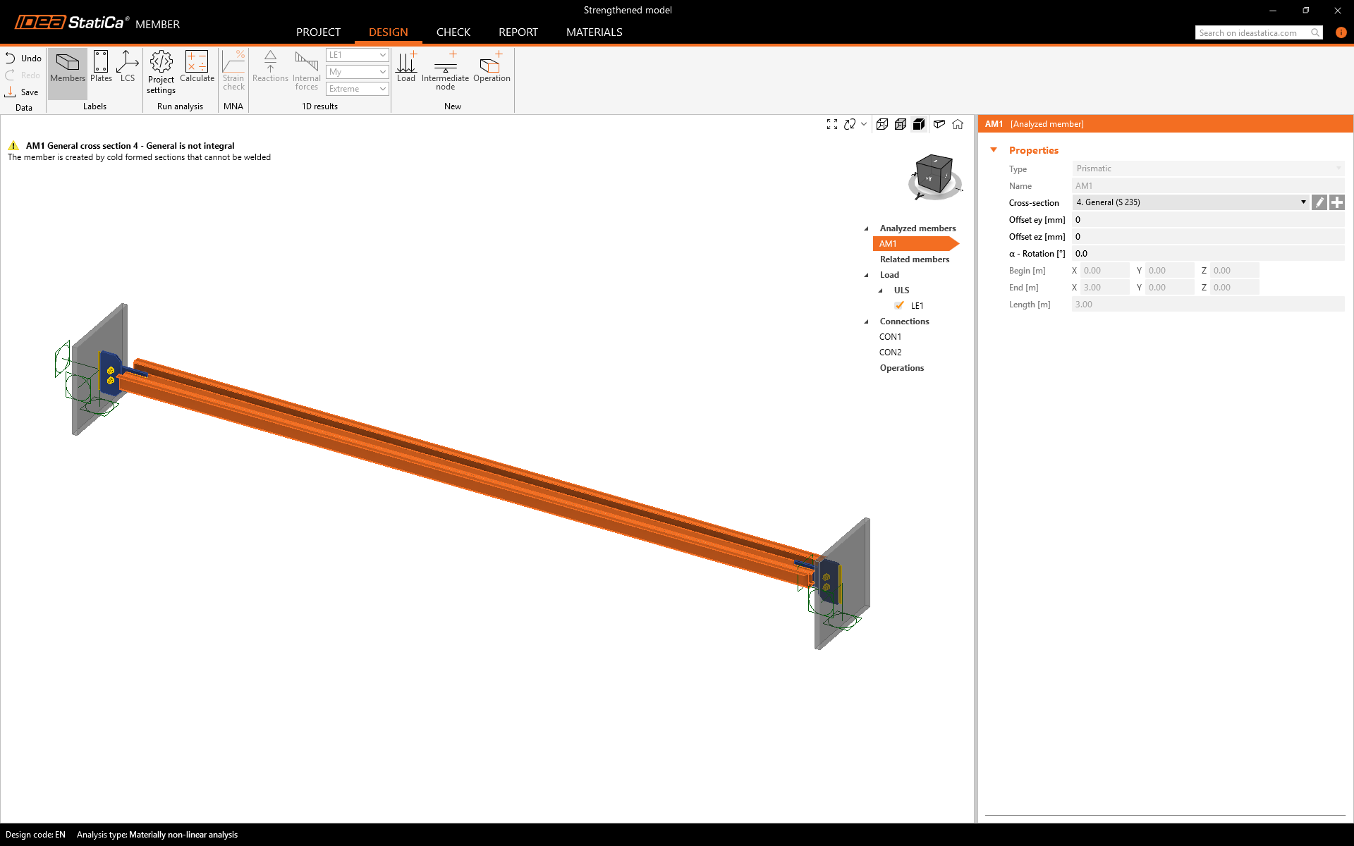
The sections behave independently.
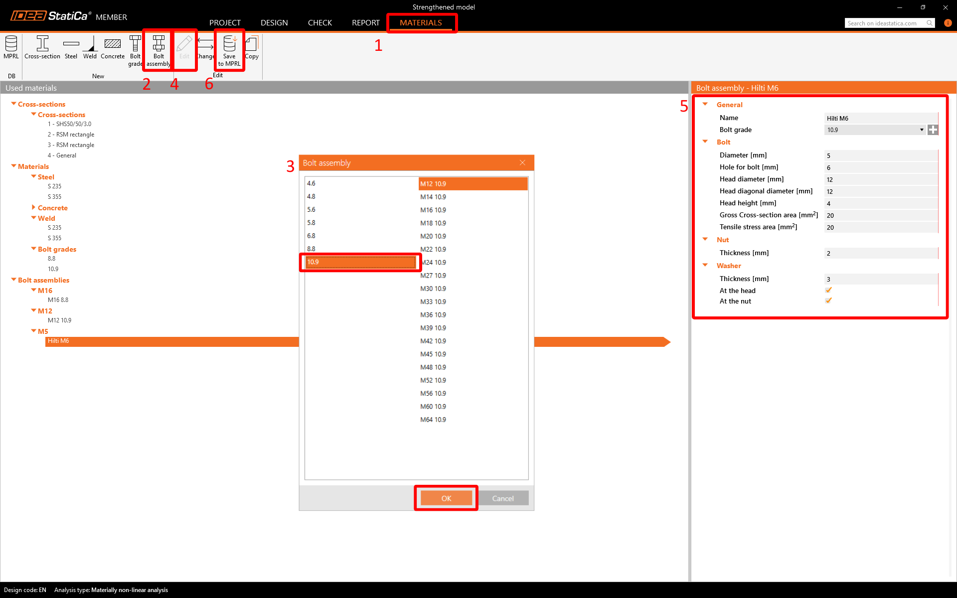
Before editing the member, create a user-defined assembly for bolt M6, which is not in the standard library. Go to Materials-->Bolt assembly-->Edit the parameters according to the table below-->Save as Hilti M6.
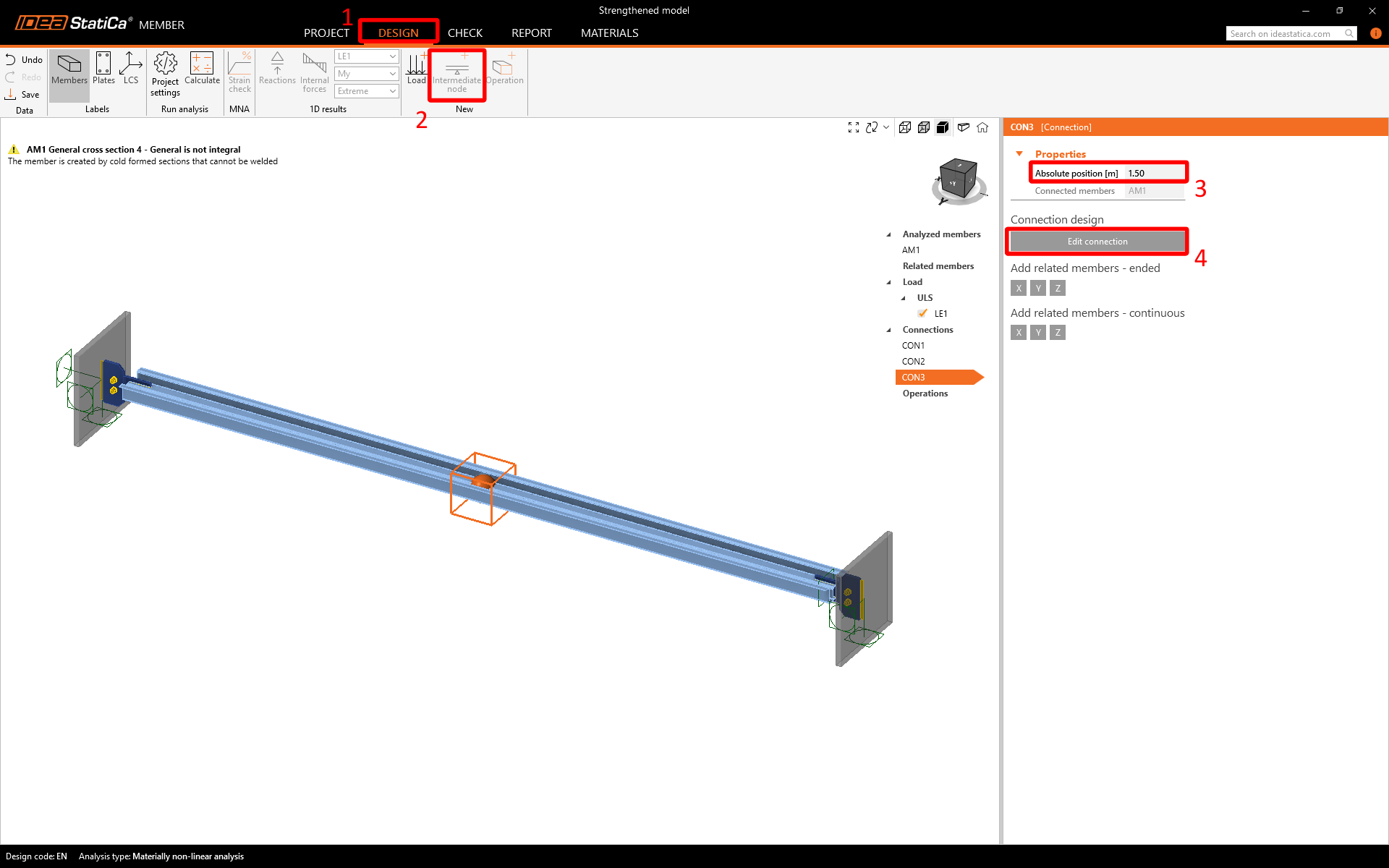
Add an Intermediate node to connect the two independent sections with bolts, with Absolute positions set 1.5 m from the member's beginning. Edit CON3.
Connection
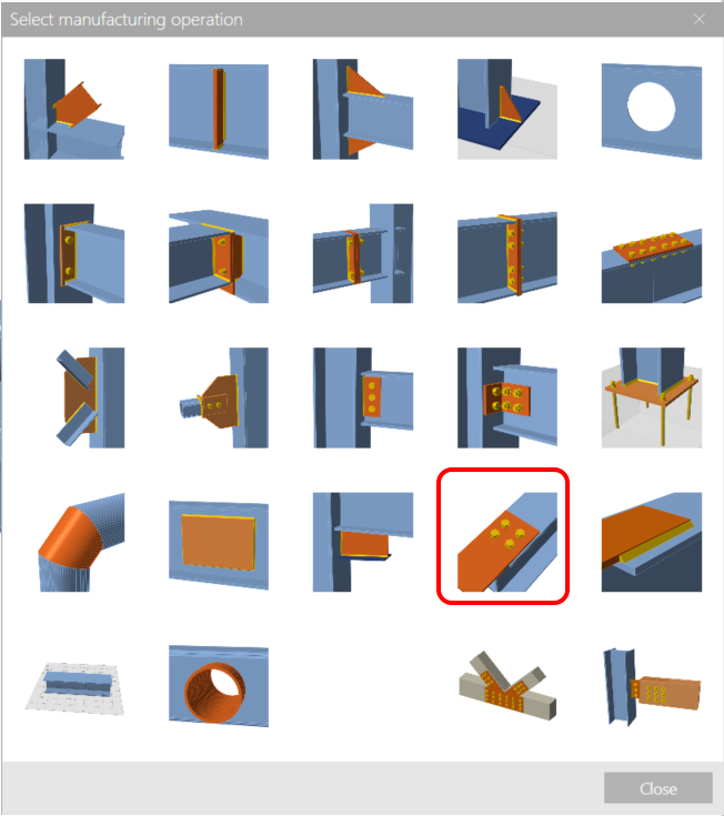
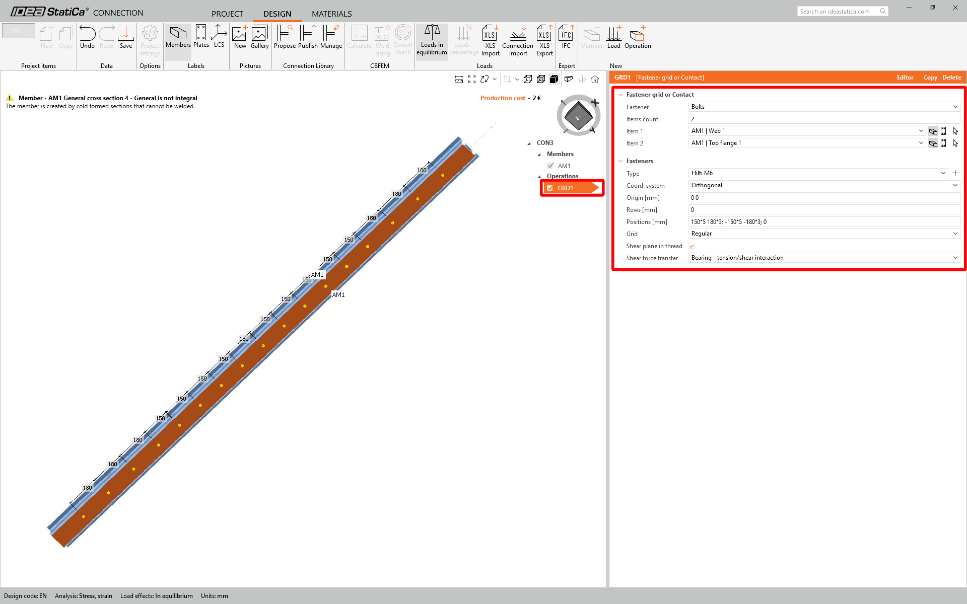
CON3 allows the user to create a bolted connection along the entire beam length. Choose the manufacturer's Fastener grid or Contact operation.
Insert the properties and layout of the bolts according to the recommendation below:
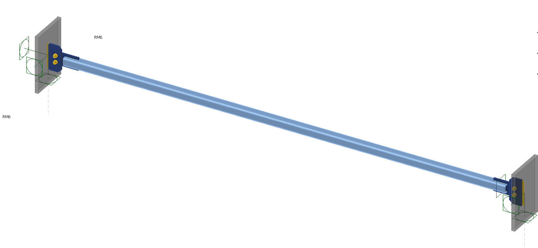
This is how the model looks in the Member app.
Check
Material Nonlinear Analysis
Switch to the Check tab and Run the MNA. The analysis will show you the areas that undergo plasticity and experience maximal stress.
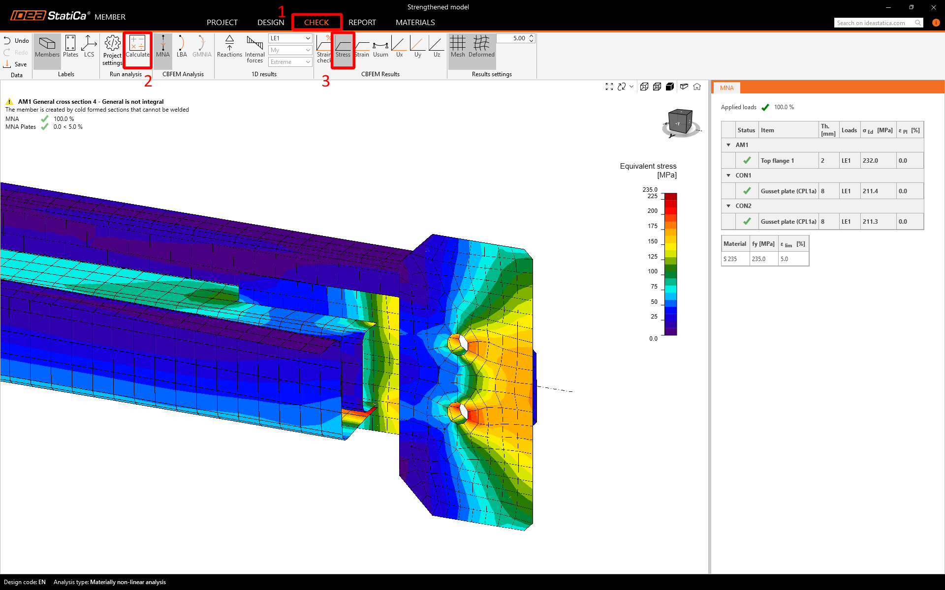
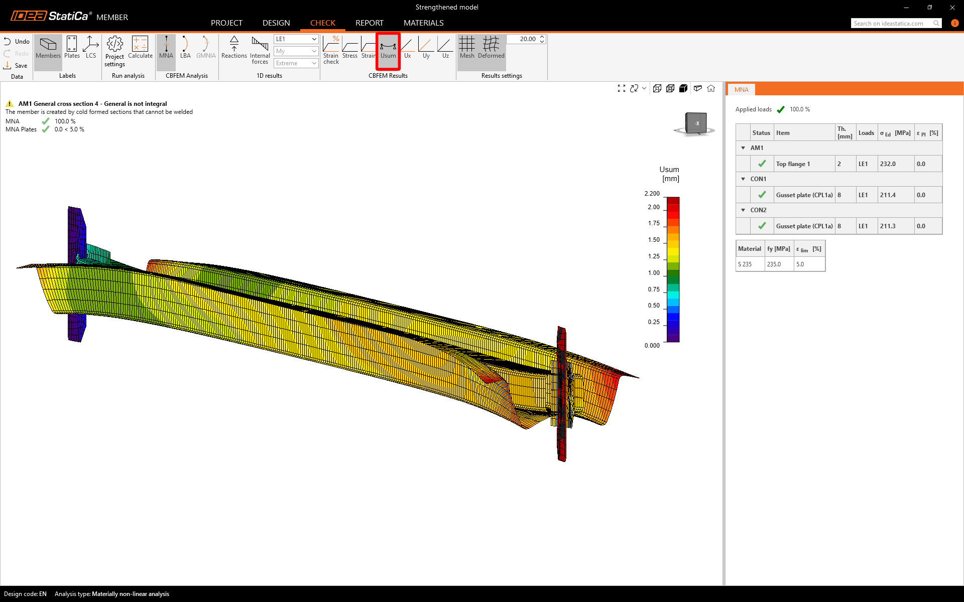
The deformation proves that the member is coacting thanks to the bolt coupling.
Linear Buckling Analysis
Launch the calculation for Linear Buckling Analysis. The first buckling shape has changed due to section strengthening, this is pure bending mode in the vertical direction. The buckling factor has increased.
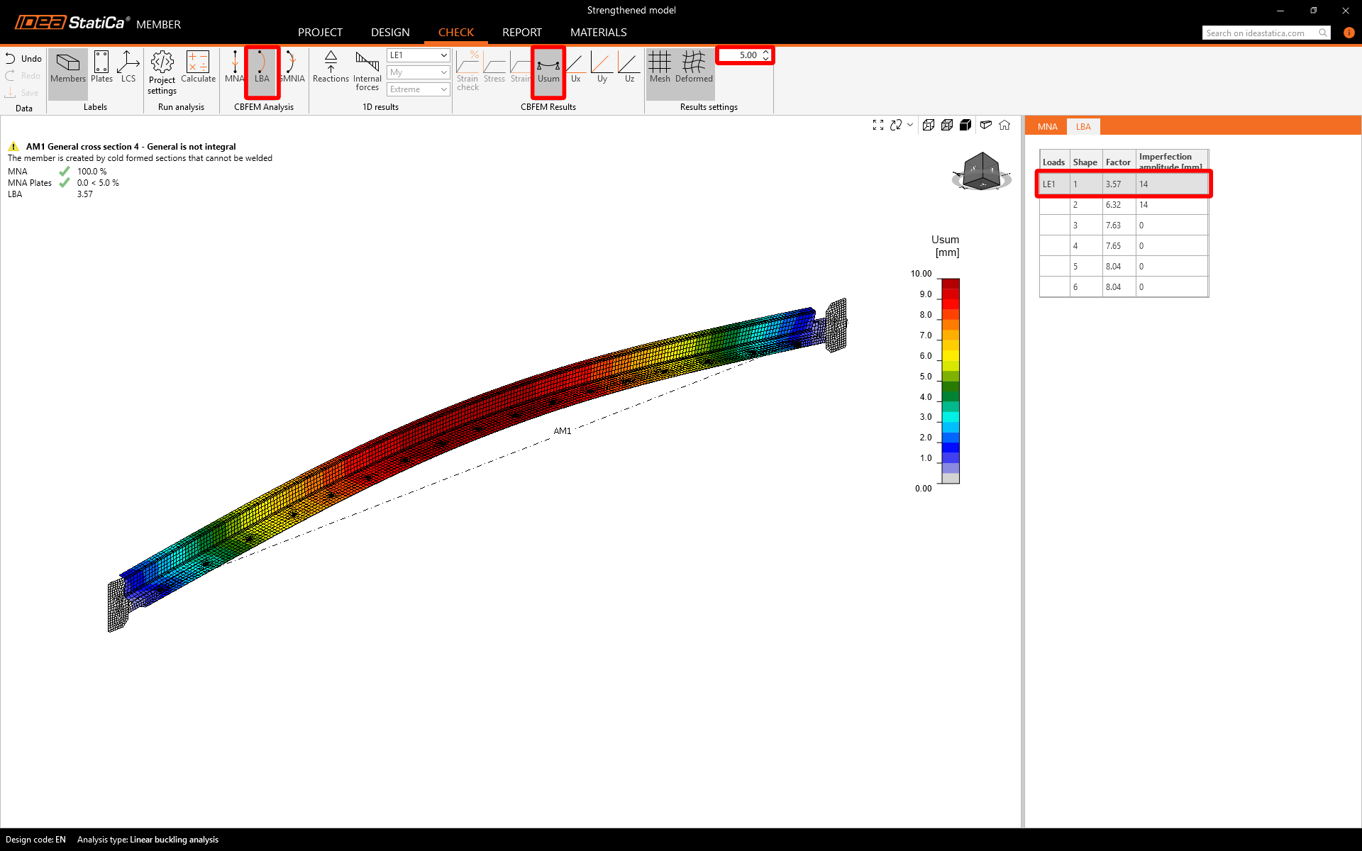
In the second mode shape, there is a simultaneous occurrence of lateral bending and section distortion at both ends of the beam.
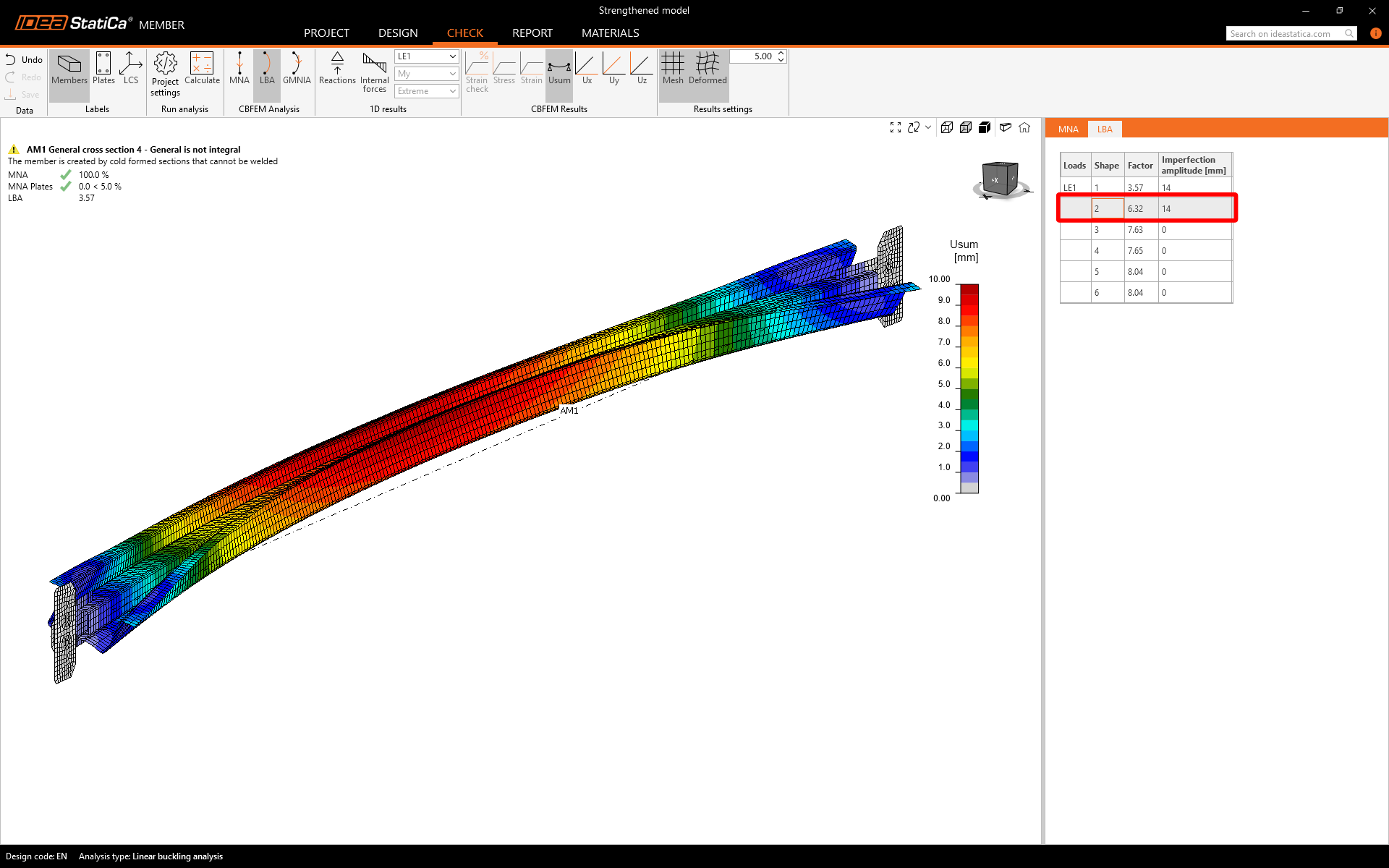
Since the buckling factors are close to each other, creating the interaction of modes guarantees the capture of all possible deformations under pressure. Four combinations of imperfections are needed to create the mutual interaction of two buckling modes.
The practical way to identify critical mode combinations is by overloading the model. This will reveal indications such as plastic strain, deformations, or unfinished GMNIA calculations (the approach for an unstrengthened model).
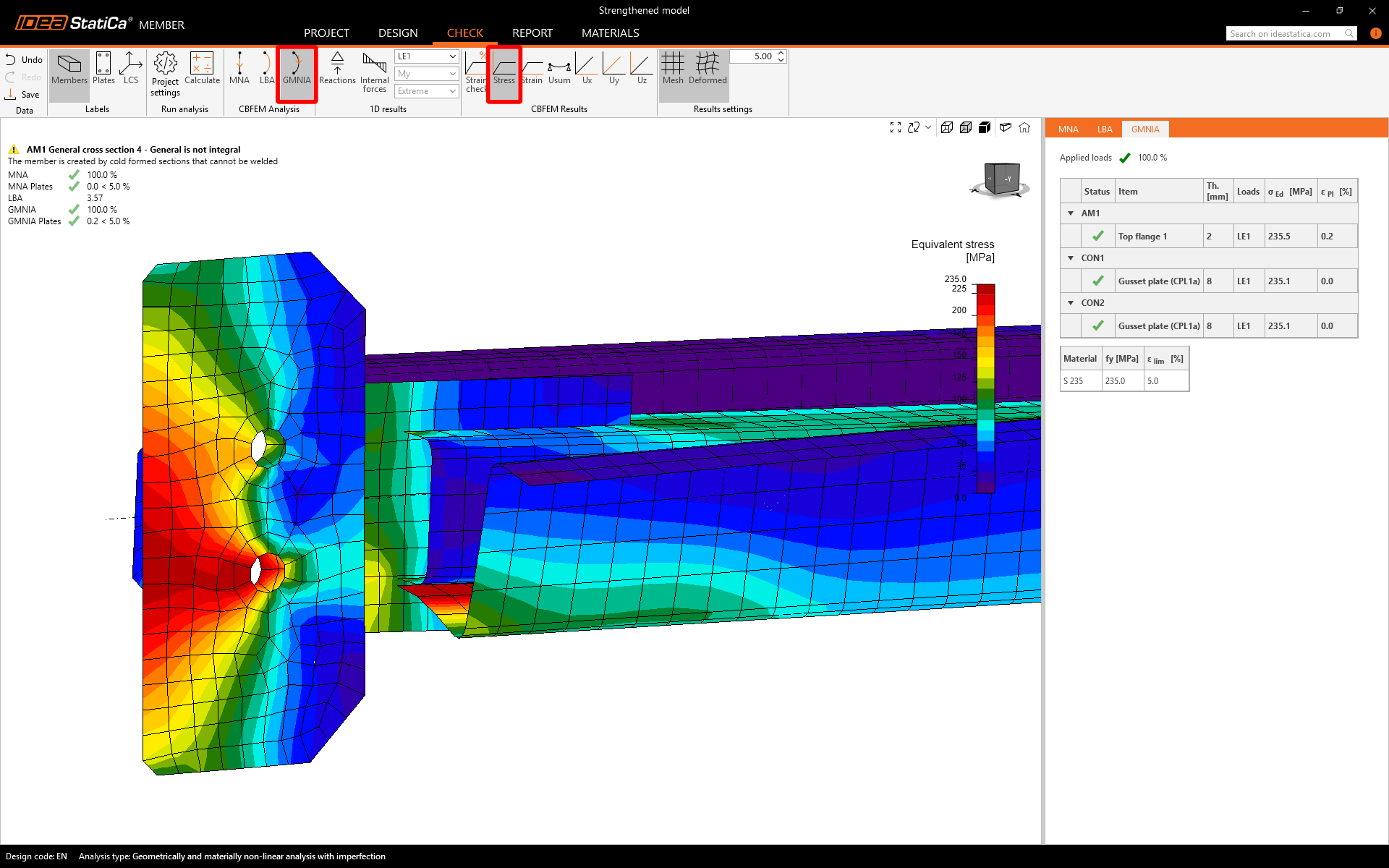
Geometrical and Nonlinear Analysis with Imperfection
After carefully selecting the imperfections and running the GMNIA, the critical spot on the connection has been identified through the equivalent stress. It is good proof of the design to report that the analysis has reached 100% completion without any stability issues, ensuring the safety of the member and all its components.
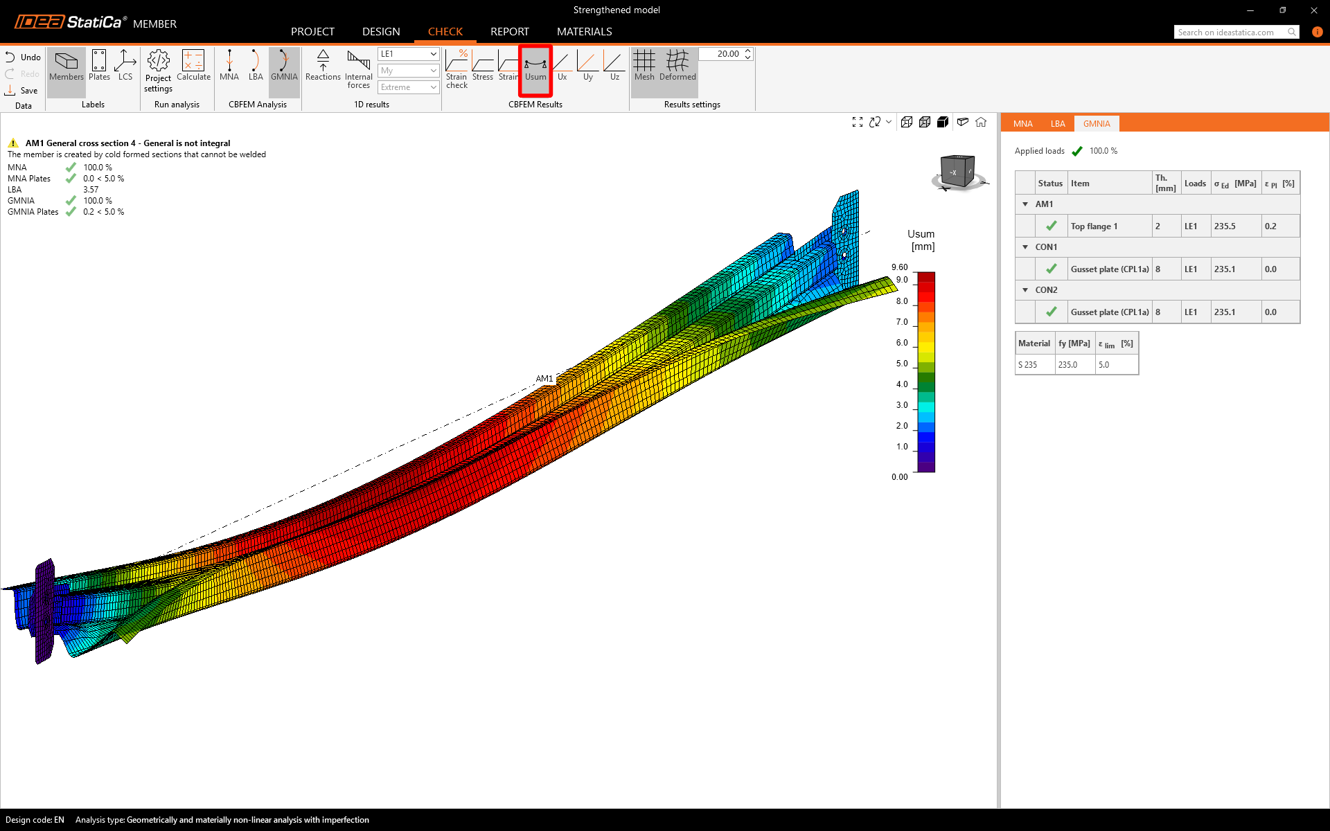
Based on the geometrical nonlinearity and imperfect shape from the previous analysis step, you can observe the evolution of second-order deflection.
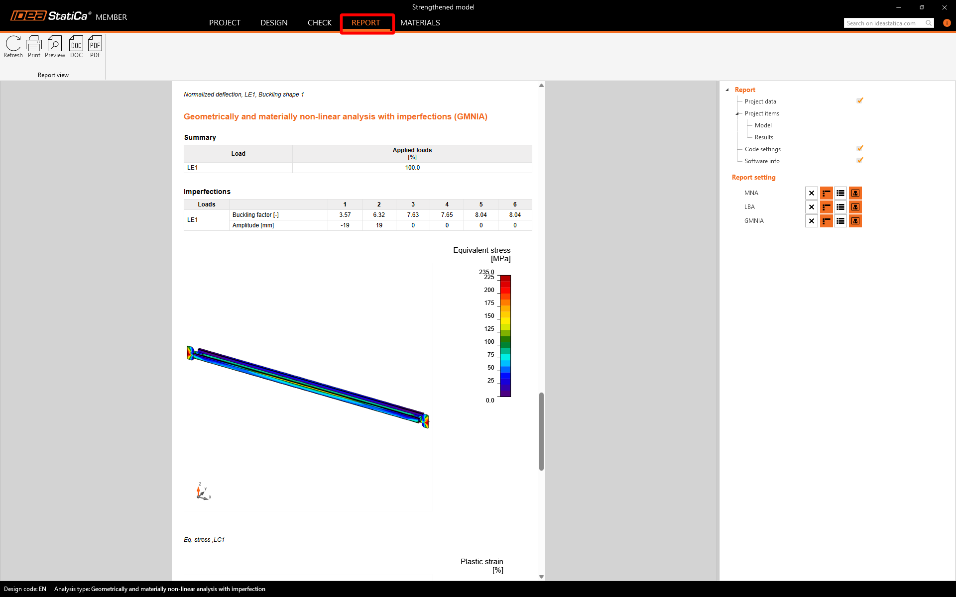
Report
Click the Report tab to automatically generate a summary of your analysis steps and code-checks that can be saved as a PDF or Word document.
Summary
This tutorial aims to provide readers with a comprehensive understanding of the process involved in evaluating structures, such as longitudinal bracing, using both hand calculations and FEA. The comparison between code-checking with hand calculations and FEA advanced analysis will enable readers to make informed decisions and gain valuable insights into the differences between the two approaches.
Takeaways:
- Hand calculations are a great tool for preliminary design.
- The critical length estimation is based on the appearance of connections, without considering the actual stiffness.
- Your initial assumptions have been confirmed through advanced FEA analysis, and the model's functionality is visually represented.
- The neglecting of joint stiffness, eccentricity, and demanding code derivation can lead to errors and misleading results.