Et si cela ne va pas dans la bonne direction ?
Tout dessinateur de structures métalliques connaît cette situation. Le modèle d'analyse structurelle global présente tous les axes des éléments convergeant proprement vers le nœud structurel. Le système structurel est ainsi clair et bien défini. Mais la structure réelle est une autre histoire.
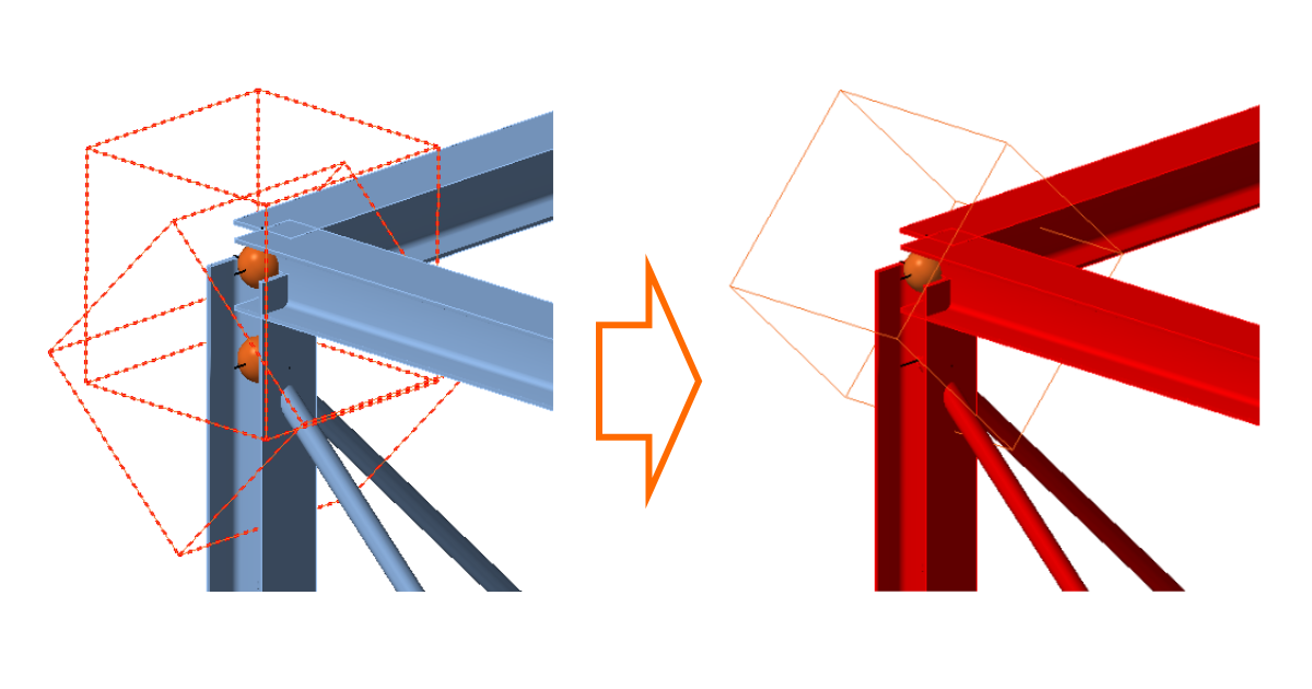
Un exemple typique est un assemblage poutre-poteau avec des éléments de contreventement à proximité. Dans cet assemblage, le poteau est le seul élément dont la position de l'axe est identique à celle du modèle structurel. Les poutres ont leurs semelles supérieures alignées, de sorte que si les hauteurs de poutre diffèrent, les axes se trouvent à des niveaux différents.
Et ce qui est encore plus courant, les axes des éléments de contreventement présentent des excentricités par rapport à la direction optimale dans le nœud. Les raisons en sont diverses – elles tiennent à la fabrication, à la constructibilité ou à des considérations esthétiques. Assez souvent, la direction idéale des éléments de contreventement entraînerait des goussets démesurément grands ou des collisions avec d'autres éléments. Parfois, d'autres contraintes technologiques ou d'équipement peuvent justifier le déplacement des éléments de contreventement hors du nœud.
Et alors surgit la question classique n° 1 :
Ce décalage aura-t-il un impact sur la structure porteuse ?
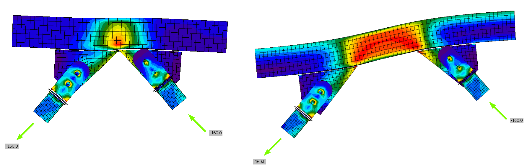
La réponse est simple : oui. Des efforts intérieurs secondaires supplémentaires sont induits dans les éléments structurels. Il s'agit d'efforts tranchants, de moments fléchissants et de moments de torsion. Ils réduisent parfois les contraintes dans les éléments, et les augmentent dans d'autres cas.
Puis vient la question n° 2 :
Cette influence justifie-t-elle l'introduction de ces excentricités dans le modèle structurel global d'origine ?
Voilà la question difficile !
Je suppose que dans la majorité des cas, ces excentricités dans les détails sont négligées dans le modèle d'ensemble. C'est compréhensible. La situation devrait être assez atypique pour causer des problèmes significatifs. Mais cela peut arriver. Et ce n'est souvent pas évident. Si ce n'est pas évident, c'est potentiellement dangereux. Et les ingénieurs structure aiment prendre des marges de sécurité.
Voici donc un exemple de scénario sécurisé :
- L'ingénieur structure calcule la structure porteuse principale et transmet le modèle de calcul par éléments finis au dessinateur.
- Le dessinateur importe le modèle (via l'export/import BIM ou manuellement) dans l'application CAO, où il conçoit tous les assemblages nécessaires à la fabrication et au montage.
- Il a ensuite besoin de la validation de l'ingénieur pour confirmer que les assemblages proposés sont conformes aux exigences du code de calcul applicable. Il retransmet donc le modèle CAO à l'ingénieur.
- L'ingénieur constate les différences entre la géométrie d'origine et la géométrie de construction fournie par le dessinateur. Et c'est là que se présente le carrefour.
a) Il ou elle effectue une revue rapide du projet et l'évalue sur la base de son expérience.
b) Il ou elle applique les efforts d'origine à la nouvelle géométrie du dessinateur et analyse les assemblages.
c) Il ou elle modifie le modèle éléments finis d'origine en fonction du modèle CAO, recalcule l'ensemble,
et analyse les assemblages.
Et où se situe IDEA StatiCa dans cette histoire ?
Les cas 4 b) et 4 c) sont précisément là où le Checkbot et l'application IDEA StatiCa Connection révèlent leurs plus grands atouts. Et cela grâce à la capacité du Checkbot à reconnaître et traiter les modèles structurels issus de divers logiciels des deux environnements – solutions éléments finis et solutions CAO.
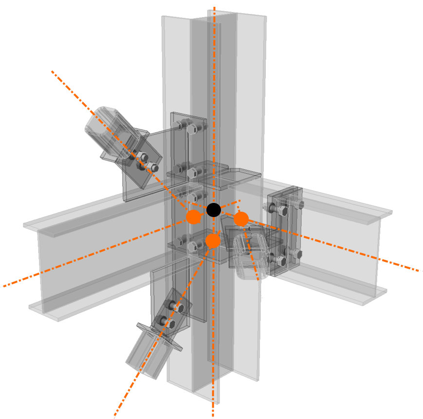
(exemple de modèle éléments finis avec excentricités)
Une fois le modèle importé, il est très facile de sélectionner un nœud structurel spécifique et de le vérifier dans l'application Connection.
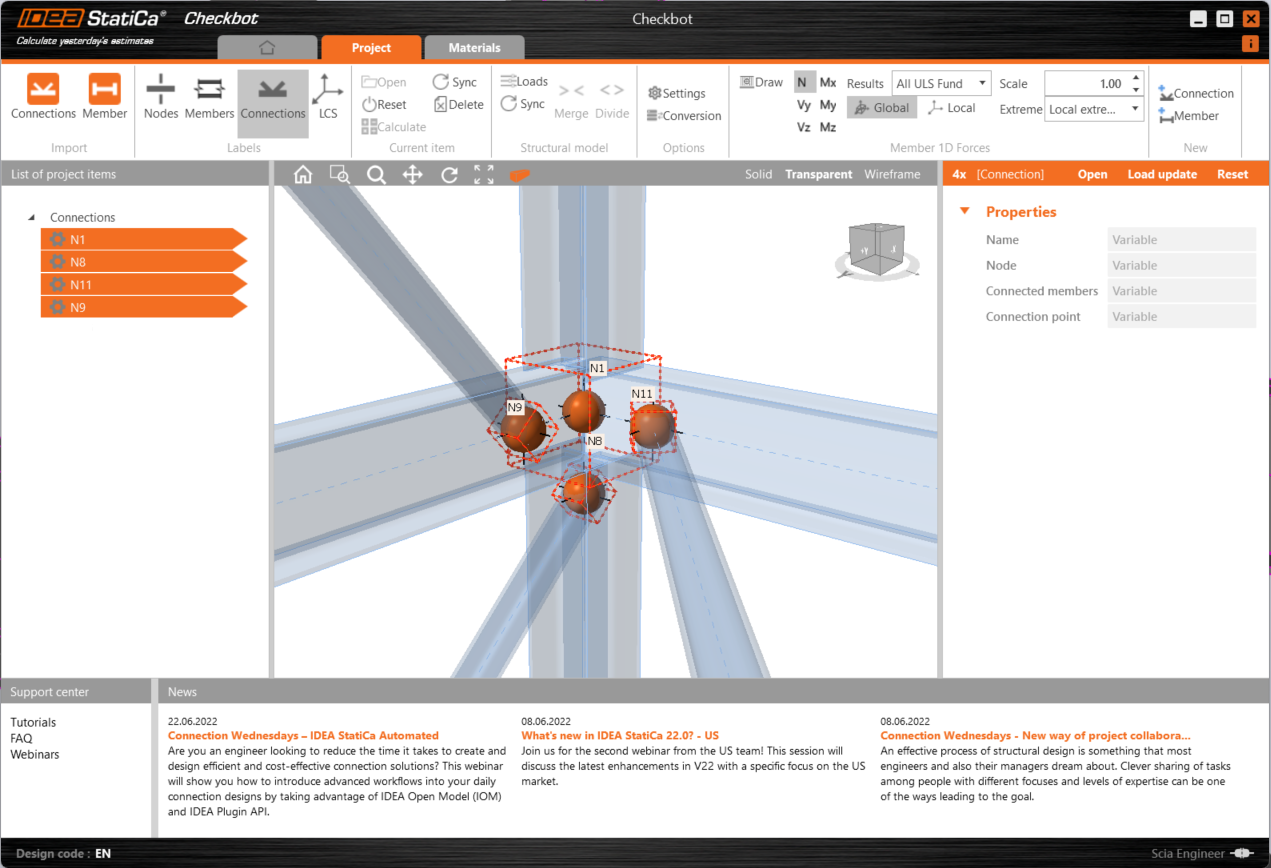
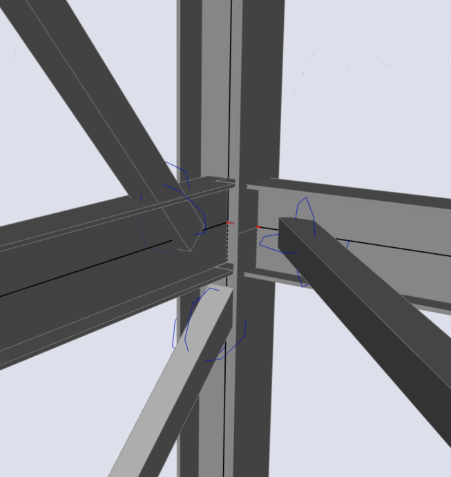
Les situations où des éléments convergent vers un même assemblage sans se rejoindre exactement au même nœud ne pouvaient pas être traitées facilement avant l'introduction de la version 22. Elles étaient évaluées comme des assemblages séparés, et l'utilisateur devait s'en sortir par une édition manuelle. Depuis IDEA StatiCa Connection v22, la situation est bien plus favorable pour l'utilisateur. Le Checkbot reconnaît automatiquement que des nœuds très proches appartiennent au même assemblage, ou l'utilisateur peut sélectionner manuellement les éléments à inclure.
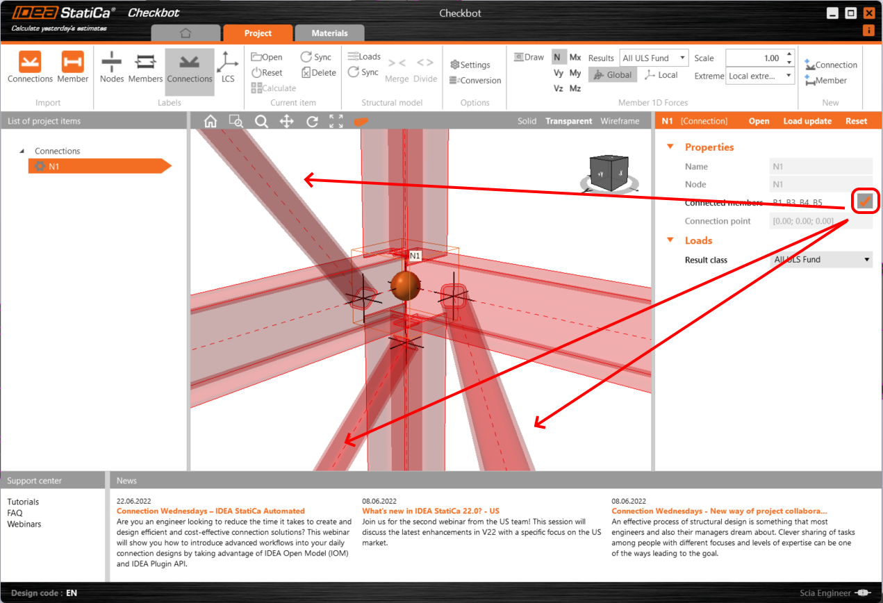
De cette façon, nous pouvons définir un ensemble spécifique d'éléments impliqués dans le modèle d'assemblage particulier.
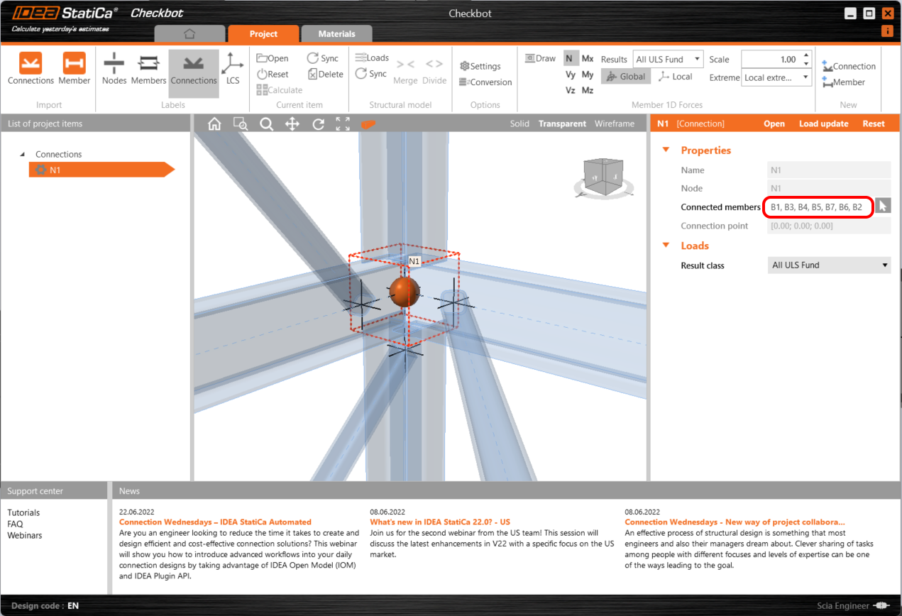
C'était peut-être une amélioration mineure de l'interface utilisateur, mais une étape importante vers l'objectif d'analyser les structures réelles et non seulement les structures théoriques.
Ainsi, quel que soit le choix de l'ingénieur entre les voies 4 b) ou 4 c), dans les deux cas, la vérification normative de l'assemblage peut être rapide, et la crainte d'une solution non sécurisée peut être écartée. Et c'est ce que nous apprécions.
Si vous êtes également intéressé par les autres améliorations apportées dans IDEA StatiCa 22, vous pouvez consulter notre article de mise à jour ici.
Essayez IDEA StatiCa gratuitement
CONTENU ASSOCIÉ
Checkbot - flux de travail BIM en lot