Highlights
Seit der ersten Veröffentlichung von IDEA StatiCa Connection im Mai 2014 haben wir eine enorme Menge an Rückmeldungen gesammelt, wie die Anwendung vereinfacht werden kann. Auf dieser Grundlage haben wir eine völlig neue grafische Benutzeroberfläche (GUI) mit vielen neuen Funktionen entwickelt, die Ihnen helfen, die Bemessung und den Normnachweis von Stahlanschlüssen zu beschleunigen – insbesondere bei einfachen Verbindungen. Das zweitwichtigste Thema im Kundenfeedback waren die BIM-Schnittstellen, weshalb wir ein leistungsstarkes Werkzeug für die Verwaltung der aus CAD- und FEA-Anwendungen exportierten Verbindungen entwickelt haben – wir können nun Verbindungsmodelle in IDEA StatiCa und anderen Anwendungen synchronisieren. Darüber hinaus gibt es mehrere neue Funktionen wie den direkten Berichtsexport, neue Modelle für die Verankerung oder den Stummel-Fertigungsvorgang.
Berechnen Sie die Schätzungen von gestern mit IDEA StatiCa!
GUI-Neugestaltung
Wir haben eine neue GUI entwickelt, um das „Gesicht" von IDEA StatiCa Connection zu vereinfachen, zu klären und zu aktualisieren. Wir haben jeden Befehl, jede Schaltfläche, jedes Menüband usw. eingehend untersucht. Wir haben deren Benutzerfreundlichkeit und den Kontext des Arbeitsablaufs diskutiert. Dies ermöglichte es uns, Platz für viele neue Funktionen zu schaffen, um die Produktivität und Genauigkeit zu steigern.
Assistent für die neue Verbindung
Der neue Verbindungsassistent hilft Ihnen, neue Verbindungen zu bemessen und den Normnachweis zu führen. Die Auswahl von Klasse, Topologie und Bemessung aus vorgefertigten Vorlagen ermöglicht es Ihnen, Hunderte von Verbindungstypen in Sekunden zu definieren. Alle Elemente sind in EC-, AISC- und CISC-Normen verfügbar.

Navigator durch Menübandregisterkarten ersetzt
Fünf Menübandregisterkarten haben das linke Navigatorfenster ersetzt.
- Projekt – Dateimenü zur Verwaltung des Projekts und der Anwendung in einem Menü.
- Registerkarte Bemessung – Bauteile, deren Geometrie, Lasteffekte und Fertigungsvorgänge ändern oder erstellen.
- Registerkarte Nachweis – Analyse kann durchgeführt und die Ergebnisse untersucht werden.
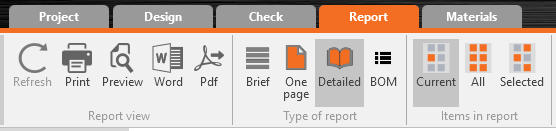
- Registerkarte Bericht – stellt das Protokoll und die Stückliste bereit.
- Registerkarte Material – Informationen über Materialien, Querschnitte, Schraubenklassen und Baugruppen sind zusammengefasst.

3D-Szene
- Aktualisierte Technologie für die Visualisierung der 3D-Szene
Wir haben die Rendering-Technologie der 3D-Szene auf die neueste Version aktualisiert. Dies führt zu einer besseren, schnelleren und flüssigeren Visualisierung (um die Visualisierung zu optimieren, aktivieren Sie die Hardwarebeschleunigung und das Antialiasing).
- Werkzeuge für den Visualisierungsstil der 3D-Szene
Die Standard-Ausgangsansicht, das Vergrößerungswerkzeug, die Perspektive und mehrere andere Werkzeuge befinden sich nun in dem grauen Streifen oberhalb der 3D-Szene. Leicht zugänglich direkt über dem Hauptarbeitsbereich.

- Baum aller Elemente in der 3D-Szene
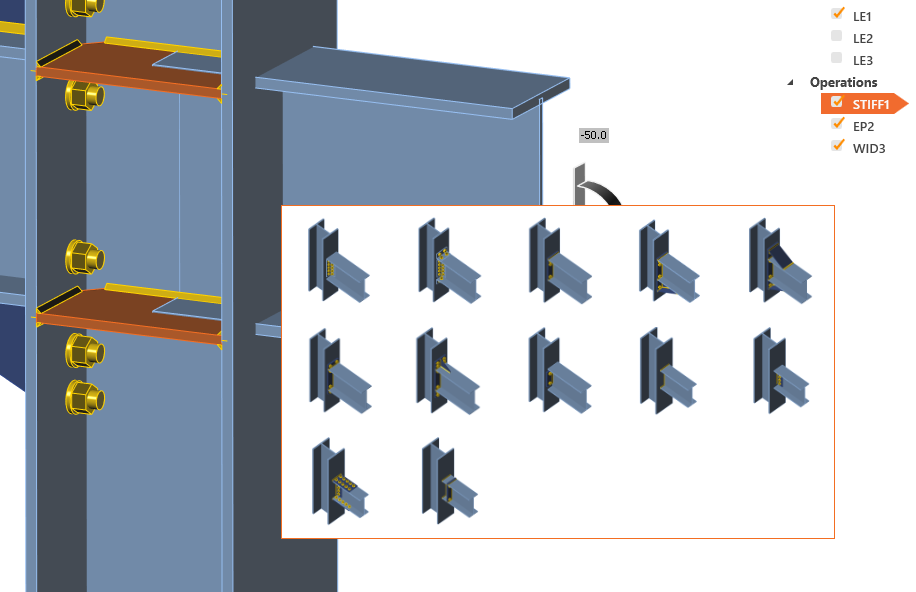
Eines der neuen Steuerelemente in der 3D-Szene ist der Baum aller Modellelemente. Im Baum sind alle Bauteile, Lasteffekte und Fertigungsvorgänge verfügbar. Dieses Steuerelement kann zur effektiven Orientierung im Modell, zum Ein- und Ausblenden von Elementen und zur Bearbeitung ihrer Eigenschaften verwendet werden. Vergessen Sie nicht, die rechte Maustaste zu verwenden, die das Menü weiterer Befehle öffnen kann.

- Eigenschaften aus der 3D-Szene auswählen
Eigenschaften, die Fertigungsvorgänge definieren, können ab sofort mit dem Werkzeug unter dem grauen Pfeilsymbol aus der 3D-Szene ausgewählt werden. Wählen Sie den Befehl und wählen Sie dann das gewünschte Bauteil in der 3D-Szene aus.

- Visualisierung von Lasteffekten
Eine bessere Lastvisualisierung zusammen mit der Eingabe über einen Elementbaum ermöglicht einen effizienten Bemessungsablauf.

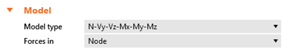
- Querkraftposition von Lasteffekt zur Bauteilbemessung verschoben
- Ergebniszusammenfassung in der 3D-Szene
Die Analyse kann auf der Registerkarte Bemessung durchgeführt werden, was eine effektive Möglichkeit zur Feinabstimmung des Modells bietet. Die Ergebniszusammenfassung wird in der 3D-Szene und auch als Ampelfunktion angezeigt.

- Befehle der rechten Maustaste
- Elementänderung
Befehle der rechten Maustaste können auch in der 3D-Szene nützlich sein. Sie können den Bauteilquerschnitt, die Schweißnaht, die Schraube und die Plattendicke ändern.
Bauteilelement:- Querschnittsänderung
- Bauteil als tragendes Bauteil festlegen
- Befehlssatz zur Definition einer Einzel-Bauteil-Verbindung. Zum Beispiel löscht der Befehl „Bereinigen" alle Fertigungsvorgänge, die dem gewählten Bauteil zugeordnet sind. Der Befehl „Ändern" bietet einen Satz möglicher Modifikationen wie Öffnungen.
- Elementänderung
Plattenelement:
- Dicke der Platte
Schweißnahtelement:
- Nahtdicke
- Material der Schweißnaht
- Schweißnahttyp
Schraubenelement:
- Durchmesser- und Güteänderung

Einzel-Bauteil-Vorlagen
Der Befehl „Verbinden" ist über einen Rechtsklick auf ein Bauteil verfügbar und erstellt eine Einzel-Bauteil-Verbindung. Im ersten Schritt muss die Fläche für die Verbindung ausgewählt werden, anschließend wird ein Satz von Einzel-Bauteil-Vorlagen angeboten.
Stückliste auf der Registerkarte Bericht
Zusammen mit den neuen Registerkarten wurde die Stückliste (BOM) zu einem Befehl im Menüband zusammengeführt. Sie ist in der Familie „Berichtstyp" zu finden.

Material- und Querschnittsbibliotheken zur Registerkarte Material zusammengeführt
Ähnlich wie bei den neuen Registerkarten wurden Querschnitte, Schraubenklassen, Schraubenbaugruppen und Materialeigenschaften zusammengeführt.

Dateimenü
Das Dateimenü wurde entwickelt, um Ihnen die Verwaltung des Projekts und der Anwendung in einem Menü zu erleichtern. Das Element „Information" ersetzt die Projektelemente aus früheren Versionen.

Automatische Modellkontrolle, Warnungen
- Singularitätswarnung
Die Singularitätsprüfung des Modells wurde implementiert. Ein neuer Status in der Ergebniszusammenfassung wird ausgegeben und in der 3D-Szene wird ein Modell mit hervorgehobenen Elementen angezeigt. Im folgenden Beispiel ist das nicht geschweißte Bauteil zu sehen.

- Bauteillänge
Die Standardlänge der Bauteile wird automatisch berechnet. Es ist nicht mehr notwendig, die Länge des Bauteils manuell zu ändern. Der Algorithmus erhöht die Länge des Bauteils nach der Definition eines Fertigungsvorgangs.
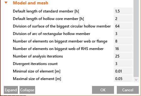
- Oberflächenunterteilung von Hohlprofilbauteilen
Für bessere Ergebnisse bei Hohlprofilbauteilen werden dedizierte Einstellungswerte für die Netz- und Unterteilungseigenschaften erstellt.
Ältere Modelle in Version 9 öffnen
Einer der Gründe für die neue GUI ist, dass viele Ingenieure uns sagten: „IDEA StatiCa Connection muss fehlertoleranter werden". Diese „Fehler" hängen in der Regel zusammen mit:
- Festlegen der korrekten Bauteillänge – bei extrem kurzen oder langen Bauteilen kann dies die Ergebnisse erheblich beeinflussen. In Version 9 legt IDEA StatiCa Connection automatisch eine geeignete Länge für alle Bauteile fest.
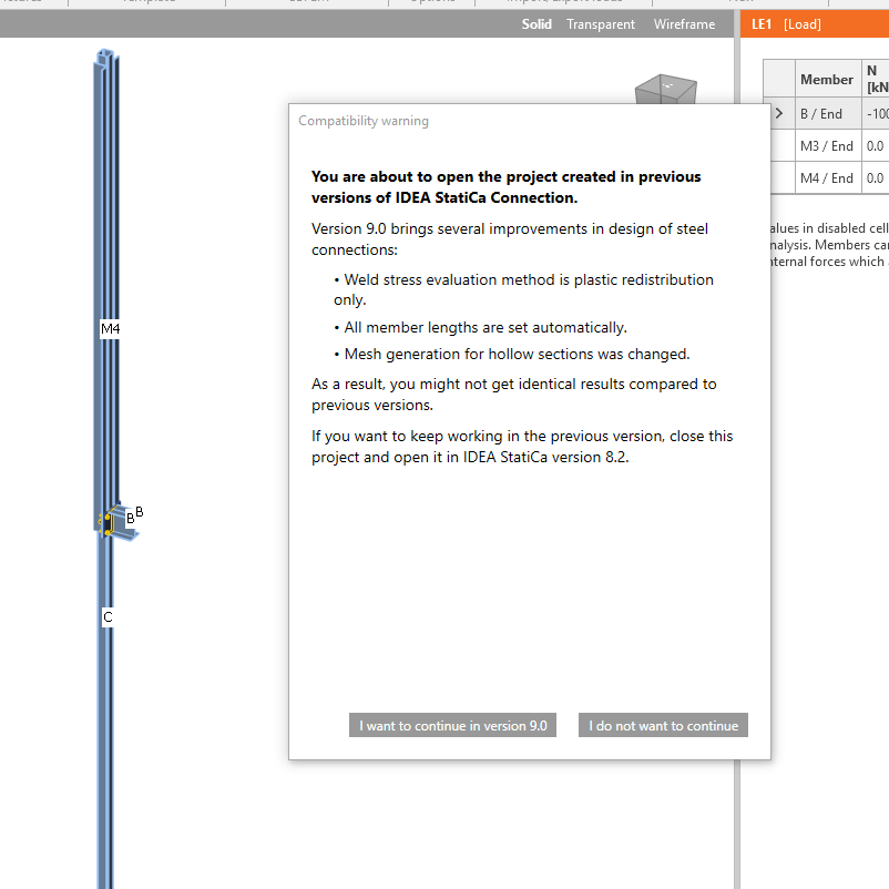
- Schweißnähte – die plastische Spannungsumlagerung ist bei weitem die genaueste Bemessungsmethode für Schweißnähte und wurde in Version 7.1 eingeführt. Während Version 8 – als Übergangsphase – war sie die Standardmethode und koexistierte mit den anderen Auswertungsmethoden. In Version 9 ist diese Methode die einzige verfügbare Option, und die anderen Auswertungsmethoden wurden entfernt, um Verwirrung bei den Benutzern zu vermeiden, wie wir über unseren Helpdesk festgestellt haben. Dies stellt sicher, dass alle Schweißnähte im Projekt sicher bemessen sind und der Norm entsprechen.
Wir haben mehrere Kontrollmechanismen für IDEA StatiCa Connection Version 9 implementiert – automatische Kontrolle, ob die Verbindung auf empfohlene Weise modelliert ist (Singularitätsprüfung, Bauteillängen, deren Versätze, …). Wenn die Verbindung nicht ordnungsgemäß modelliert ist, wird die Berechnung unterbrochen oder eine Fehlermeldung angezeigt. Bitte beachten Sie, dass aufgrund all dieser Verbesserungen das Öffnen von Projekten aus früheren Versionen zu einer anderen Modellgeometrie führen kann, die möglicherweise weitere Bearbeitung erfordert.
Wir haben auch die Vernetzung von Hohlprofilbauteilen verbessert – IDEA StatiCa Connection Version 9 erzeugt ein feineres Netz bei Hohlprofilbauteilen, was im Vergleich zu älteren Versionen zu leicht abweichenden Ergebnissen führen kann.
Beim Öffnen eines Projekts aus einer älteren Version wird ein Kompatibilitätshinweis angezeigt:
IDEA StatiCa Connection 9 ist ein Werkzeug, das Verbindungen jeder Topologie und Belastung bemessen und nachweisen kann. Darüber hinaus gibt es klare Empfehlungen/Grenzen dafür, „wie" dies zu tun ist und was bei der Verbindungsbemessung zu vermeiden ist. Dies gewährleistet Sicherheit und Konsistenz bei allen am Bemessungsprozess beteiligten Beteiligten.
BIM
Bis Version 8.2 haben wir 15 BIM-Schnittstellen mit verschiedenen FEA/CAD-Anwendungen entwickelt. Diese Schnittstellen sind einseitig, d. h. ein einfacher Export der Daten aus FEA/CAD-Anwendungen in IDEA StatiCa.
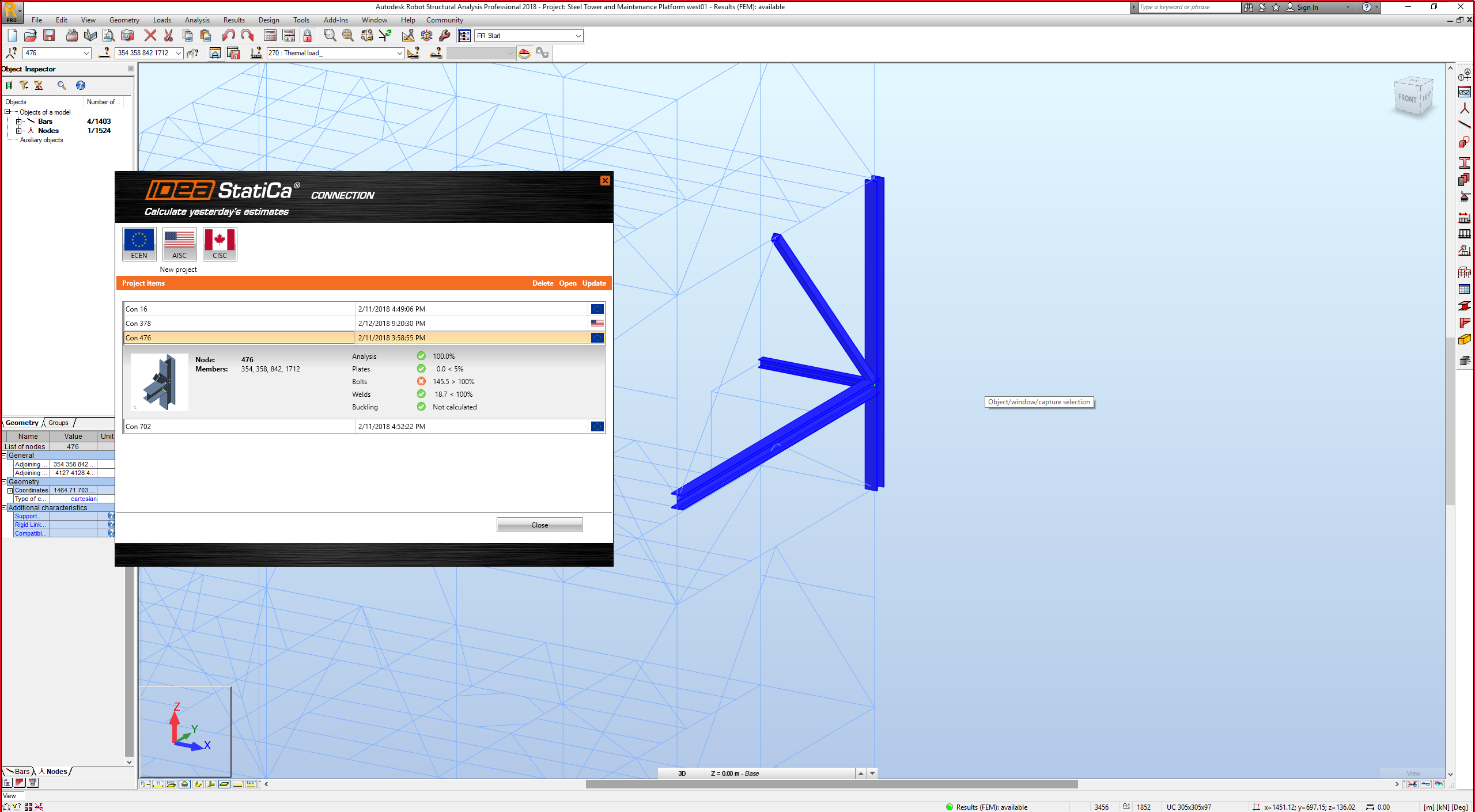
Version 9.0 bringt eine erhebliche Verbesserung dieses Arbeitsablaufs – wir sind nun in der Lage, das IDEA StatiCa-Modell automatisch entsprechend den Änderungen im ursprünglichen FEA/CAD-Modell zu aktualisieren. Wir haben auch eine übersichtliche Möglichkeit implementiert, alle aus einem bestimmten FEA/CAD-Modell exportierten IDEA-Verbindungen/Träger zu verwalten – sie werden in einem Fenster des Verbindungsmanagers mit Ergebnisübersicht (kleines Bild, Ergebniszusammenfassung, Norm usw.) angezeigt.
Um Ihre Bemessung zu visualisieren, haben wir auch eine automatische Hervorhebung der ausgewählten Verbindung in der FEA/CAD-Anwendung implementiert – Sie sehen sofort die grundlegende Übersicht dieser bestimmten Verbindung beispielsweise in SAP 2000.
CAD-Schnittstellen (Tekla Structures und Advance Steel)
Bisher mussten wir die Verbindung jedes Mal aus TS/AS in ein neues Projekt exportieren. Das bedeutete, die Lasteffekte erneut einzugeben.
Version 9.0 ändert dies grundlegend:
- Wir erstellen einen Stahlanschluss in TS/AS
- Wir exportieren ihn in IDEA StatiCa, geben Lasten ein und führen einen Normnachweis durch
- Angenommen, wir möchten die Verbindungsbemessung optimieren/ändern – wir kehren zu TS/AS zurück und nehmen die notwendigen Änderungen vor (Schraubenpositionen, Schweißnahtdicke, Steife hinzufügen usw.)
- Dann klicken wir auf die Schaltfläche „Aktualisieren" im in TS/AS eingebetteten IDEA-Plugin, und alle Änderungen werden automatisch in unserem IDEA StatiCa-Projekt übernommen – die Lasteffekte müssen nicht erneut manuell eingegeben werden
- Wir können dies mehrmals wiederholen, um die Bemessung zu optimieren und gleichzeitig sicherzustellen, dass alle Daten sowohl in TS/AS als auch in IDEA StatiCa korrekt eingegeben sind

FEA-Schnittstellen (SAP 2000, Robot, STAAD.Pro usw.)
Bisher mussten wir die Verbindung/den Träger jedes Mal aus FEA-Anwendungen in ein neues Projekt exportieren. Das bedeutete, die Verbindung erneut zu bemessen.
Version 9.0 ändert dies grundlegend:
- Wir wählen einen Knoten in der FEA-Anwendung aus
- Wir exportieren ihn in IDEA StatiCa (Geometrie, Querschnitte, Lasteffekte), bemessen die Verbindung und führen einen Normnachweis durch
- Angenommen, wir möchten die Verbindungsbemessung optimieren/ändern – wir kehren zur FEA-Anwendung zurück und nehmen die notwendigen Änderungen vor (Lasten, Querschnitte usw.)
- Dann klicken wir auf die Schaltfläche „Aktualisieren" im in der FEA-Anwendung eingebetteten IDEA-Plugin, und alle Änderungen werden automatisch in unserem IDEA StatiCa-Projekt übernommen – die Verbindung muss nicht erneut manuell bemessen werden
- Wir können dies mehrmals wiederholen, um die Bemessung zu optimieren und gleichzeitig sicherzustellen, dass alle Daten sowohl in der FEA-Anwendung als auch in IDEA StatiCa korrekt eingegeben sind
Sonstiges
Plastische Umlagerung in Schweißnähten als Standardmethode für die Schweißnahtspannungsauswertung
Wenn ein elastisches Materialmodell für Schweißnähte angenommen wird, liefert das Finite-Elemente-Modell Spannungsspitzen an bestimmten Stellen von Unregelmäßigkeiten (Enden, wo sich 2 Schweißnähte treffen ...). Die Schweißnahtkapazität würde an diesen kleinen Stellen mit Spannungsspitzen sehr schnell erreicht werden. Das würde bedeuten, dass die Schweißnaht im Vergleich zur traditionellen Handberechnung einen sehr geringen Lastwiderstand aufweist. Daher ist eine Art Mittelung notwendig. Früher haben wir den Mittelwert über die Schweißnahtlänge (geeignet für den Flansch im Beispiel des gebogenen Breitflanschträgers), lineare Interpolation (geeignet für den Steg) oder das Maximum (sehr sicher) bereitgestellt. Der Benutzer konnte seine Wahl treffen, dies erforderte jedoch ein Verständnis der traditionellen Schweißnahtbemessung und der Finite-Elemente-Bemessung. Darüber hinaus konnte die Verwendung des Mittelwerts in einigen Fällen zu einer unsicheren Bemessung führen.
Daher haben wir entschieden, dass die Software die Mittelung korrekt und automatisch durchführen muss, und nach vielen Versuchen und Tests haben wir die plastische Umlagerung in Schweißnähten entwickelt. Ein Volumenelement wird zwischen die Interpolationsverbindungen eingefügt. Die plastische Umlagerung dient dazu, den Widerstand der Schweißnahtkomponente korrekt zu bestimmen, indem Spannungsspitzen in weitere Schweißnahtelemente umgelagert werden. Die gefährlichsten Bereiche wurden als Schweißung an unversteiften Flanschen erkannt (EN 1993-1-8 - Abschn. 4.10). AISC und CISC verwenden einen anderen Ansatz für die Schweißnahtbemessung und erfordern eine Abminderung für mehrfach orientierte Schweißnähte. Wir haben uns auch mit diesem Problem befasst und ein spezielles Schweißnaht-Materialmodell für AISC und CISC entwickelt. Plastische Umlagerung bedeutet nicht, extreme Verformungen der Schweißnaht zuzulassen.
Die plastische Umlagerung in Schweißnähten ist seit Version 9.0 die Standardmethode und die einzige verfügbare Methode für die Schweißnahtspannungsauswertung.
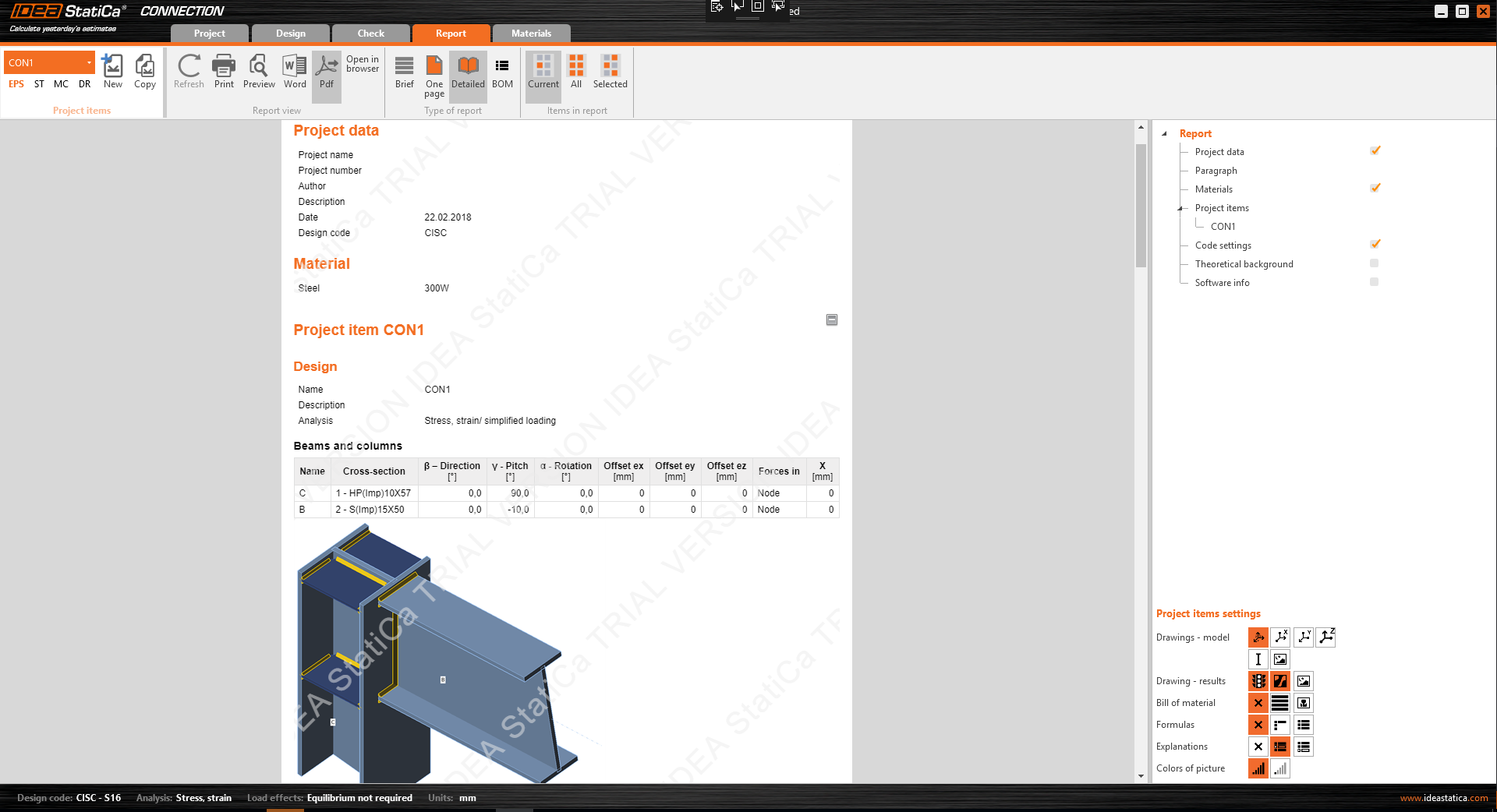
Export des Berichts direkt in .doc und .pdf
Wir haben den direkten Export in Microsoft Word (doc) und Adobe Reader (pdf) Dateiformate implementiert. Ab sofort kann der Export mit nur einem Befehl durchgeführt werden.
Aktualisierungen der AISC- und CISC-Normanforderungen
- Verbessertes Materialdiagramm für die plastische Umlagerung von Spannungen in Schweißnähten.
- Verbesserte Eigenschaften eines nichtlinearen Federelements für die Interaktion von Quer- und Zugkräften in der Schraube auf Lochleibung – Zug-/Querkraft-Interaktion.
- Aktualisierte Verankerungsbemessung.
- Anker, die einen gemeinsamen Betonausbruchkegel bilden, werden nun als Gruppe bewertet, was einen erhöhten Widerstand ermöglicht.
- Anker an einer Fußplatte werden als Gruppe auf Betonausbruch durch Querkraft geprüft. Es wird angenommen, dass nur die Anker in der Nähe der Kante in Richtung der Querkraft die gesamte auf die Fußplatte wirkende Querkraft übertragen.
- Wenn eine Betonausbruchprüfung vom Benutzer nicht gefordert wird, wird angenommen, dass die Zug- und Querkraft über die Betonbewehrung übertragen wird. Dem Benutzer wird eine aggregierte Kraft einschließlich der Abhebekräfte bereitgestellt, die über die Bewehrung übertragen werden müssen.
AISC-Formeln in den Ergebnissen
Eine wesentliche Verbesserung der bereitgestellten Normnachweis-Formeln wurde vorgenommen. Alle Formeln sind nun erläutert und die Werte werden ebenfalls angegeben.

Verankerung
- Ein neues Modell für die Schubknagge
Das Netz der Schubknagge wird nun auf die gleiche Weise erstellt wie das Netz der Bauteile. 2D-Finite-Elemente – Platten sind mit Schweißnahtelementen mit der Fußplatte verbunden. Die Schubknagge selbst kann ohne Einschränkungen in der Fußplattenebene positioniert und gedreht werden.
- Bewertung der Schweißnähte und des Betons auf Lochleibung
Nachweise des Betons auf Lochleibung und Nachweise der Schweißnähte auf die gleiche Weise wie Schweißnahtnachweise an beliebiger Stelle in der Verbindung wurden in die Ergebnistabellen implementiert.

- Ein neues Modell für Anker mit Abstand zur Unterlage
Stark belastete Anker mit Abstand zur Unterlage sind mit zwei plastischen Gelenken ausgestattet, um eine realistischere Kraftverteilung zu ermöglichen.
Stummel-Fertigungsvorgang
Eine wesentliche Verbesserung des Stummel-Fertigungsvorgangs wurde implementiert. Nun kann der Stummel selbst ordnungsgemäß geändert werden. Der Querschnitt des Stummels kann unabhängig vom Hauptbauteil festgelegt und mit Versätzen zum Hauptbauteil positioniert werden.

Standard-Netzeinstellungen für Hohlprofile (KHP und RHP)
Die Standard-Netzeinstellung für Hohlprofilbauteile wurde verbessert. Die Netzgröße des Bauteils mit dem größten Durchmesser verwendet die Standardeinstellungen aus dem Normsetup, und das Netz kleinerer Bauteile wird in Abhängigkeit vom Bauteildurchmesser angepasst. Ziel ist es, auf jedem der Bauteile die gleiche Netzgröße zu erzeugen, was die Genauigkeit der Ergebnisse erhöht.

Schaltfläche zum Teilen in sozialen Medien
Ein Rechtsklick in die 3D-Szene öffnet den Befehl „Auf LinkedIn oder Facebook teilen". Das aktuelle Bild aus der 3D-Szene wird auf Ihrem Social-Media-Konto veröffentlicht (Anmeldung erforderlich).

Rahmen für Test- und Bildungsversion
- Testversion
Ein neuer Ansatz für die Testversion wurde implementiert. 14-tägige Testcodes werden automatisch an jeden Interessenten nach dem Ausfüllen eines Formulars versandt. Eine Hardware-Signatur wird implementiert, sodass Interessenten nur eine Testversion auf einem bestimmten PC oder Laptop aktivieren können. Während der Aktivierung werden die Hardware-Informationen ausgelesen (so wie es AutoCAD und andere Software tun). Der Hintergrund des Berichts und verschiedene Szenen der Software werden mit einem Wasserzeichen versehen. Ein neuer Ablauf-Countdown wird oben im Hauptfenster angezeigt.

- Bildungsversion
Ein neuer Ansatz für die Bildungsversion wurde implementiert. 365-tägige Testcodes werden nach dem Ausfüllen eines Webformulars an jeden Interessenten versandt. Der Hintergrund des Berichts und verschiedene Szenen der Software werden mit einem Wasserzeichen versehen. Nur ein PDF-Ausdruck mit Wasserzeichen ist möglich.
Projekte aus der Bildungsversion können in der kommerziellen Version nicht geöffnet/verwendet werden (sie werden dauerhaft „markiert" und eingeschränkt).

