Descriere
Se studiază o îmbinare T uniplanară a unui element diagonal cu secțiune tubulară dreptunghiulară (RHS) cu o talpă cu secțiune deschisă, situată într-un grătar cu zăbrele. Elementul diagonal RHS este sudat direct pe talpa H sau I, secțiuni deschise, fără utilizarea plăcilor de ranforsare. Predicția prin metoda elementelor finite bazată pe componente (CBFEM) este verificată cu metoda modurilor de cedare (FM) implementată în EN 1993-1-8:2005.
Model analitic
În îmbinarea T uniplanară a secțiunilor tubulare dreptunghiulare sudate cu secțiunile deschise apar trei moduri de cedare: curgerea locală a elementului diagonal, numită cedarea elementului diagonal, cedarea inimii tălpii și forfecarea tălpii. Toate aceste moduri de cedare sunt examinate în acest studiu; a se vedea Fig. 7.4.1. Sudurile sunt proiectate astfel încât să nu fie componenta cea mai slabă a unui nod, conform EN 1993-1-8:2005. Elementele grătarelor cu zăbrele sunt solicitate de forțe normale și momente încovoietoare. Punctul de acțiune al forțelor interioare ale îmbinării T este descris după cum urmează:
Talpă H/I solicitată axial
Forțele normale din talpa din dreapta și din stânga unei îmbinări T acționează în direcția axei longitudinale a tălpii.
Talpă H/I solicitată la difracție
Momentele încovoietoare din dreapta și din stânga unei îmbinări T în planul îmbinării T sunt considerate în talpă, iar aceste momente încovoietoare se rotesc în jurul uneia dintre axele din planul secțiunii transversale a tălpii pentru rotația în planul îmbinării T.
Element diagonal RHS solicitat axial
Forța normală din elementul diagonal al unei îmbinări T acționează în direcția axei longitudinale a elementului diagonal.
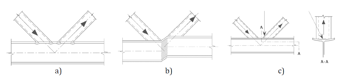
\[ \textsf{\textit{\footnotesize{Fig. 7.4.1 Moduri principale de cedare a) cedarea inimii tălpii, b) forfecarea tălpii (în cazul unui rost), c) cedarea elementului diagonal}}}\]
Rezistența inimii tălpii este determinată folosind metoda prezentată în secțiunea 7.6 din EN 1993-1-8:2005, descrisă în (Wardenier et al., 2010). Tensiunile din elementul diagonal sunt transferate prin talpa cornier a tălpii către o arie efectivă a inimii tălpii. Această arie este situată în inima tălpii în punctul în care pereții elementului diagonal intersectează inima tălpii. Rezistența axială de calcul a nodului este minimul rezistențelor de calcul:
Cedarea inimii tălpii
\[N_{\mathrm{i,Rd}} = \frac{f_{\mathrm{y0}} \cdot t_{\mathrm{w}} \cdot b_{\mathrm{w}}}{\sin(\theta_{\mathrm{i}}) \cdot \gamma_{\mathrm{M5}}}\]
Forfecarea tălpii
\[N_{i,\mathrm{Rd}}=\frac{f_\mathrm{y0}\,A_\mathrm{v}}{\sqrt{3}\,\sin\theta_\mathrm{i}\cdot \gamma_{\mathrm{M5}}}\]
Cedarea elementului diagonal
\[N_{i,\mathrm{Rd}}=2\,f_\mathrm{y1}\,t_\mathrm{1}\,p_{\mathrm{eff}}/\gamma_{\mathrm{M5}}\]
unde
\[p_{\mathrm{eff}}=t_\mathrm{w}+2r+7\,t_\mathrm{f}\,\frac{f_\mathrm{y0}}{f_\mathrm{y1}}\]
și \(A_\mathrm{v}\) este aria efectivă la forfecare.
Rezistența la încovoiere de calcul a nodului este minimul rezistențelor de calcul:
Cedarea inimii tălpii
\[M_{\mathrm{ip,Rd}} = \frac{0.5 \, f_{\mathrm{y0}} \, t_{\mathrm{w}} \, b_{\mathrm{w}} \, h_1}{\gamma_{\mathrm{M5}}}\]
Cedarea elementului diagonal
\[M_{\mathrm{ip,Rd}}=f_\mathrm{y1}\,t_\mathrm{1}\,b_{\mathrm{eff}}\,(h_\mathrm{1}-t_\mathrm{1})/\gamma_{\mathrm{M5}}\]
unde
\[b_{\mathrm{w}} = \frac{h_1}{\sin \theta_{\mathrm{i}}} + 5 \cdot t_{\mathrm{f,0}} + r \;\leq\; 2 \, t_{\mathrm{i}} + 10 \cdot (t_{\mathrm{f,0}} + r)\]
\[b_{\mathrm{eff}}=t_\mathrm{w}+2r+7\,t_\mathrm{f}\,\frac{f_\mathrm{y0}}{f_\mathrm{y1}}\]
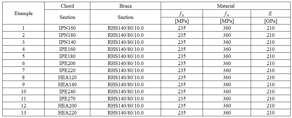
O prezentare generală a exemplelor considerate solicitate de forță axială este descrisă în Tab. 7.4.1. O prezentare generală a exemplelor considerate solicitate de moment încovoietor este descrisă în Tab. 7.4.2. Geometria unui nod cu dimensiuni este prezentată în Fig. 7.4.2.
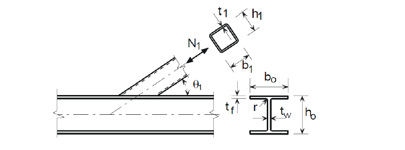

\[ \textsf{\textit{\footnotesize{Fig. 7.4.2 Geometria nodului cu dimensiuni}}}\]
Tab. 7.4.1 Exemple de noduri solicitate de forță axială
Tab. 7.4.2 Exemple de noduri solicitate de moment în plan
Verificarea rezistenței
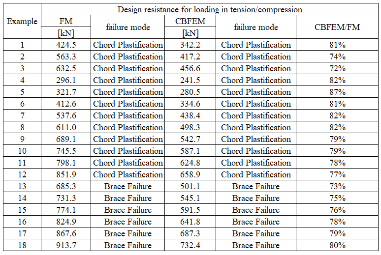
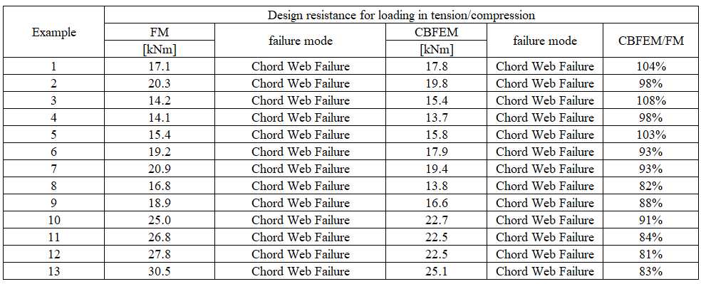
Studiul s-a concentrat pe compararea modurilor de cedare și predicția rezistenței de calcul. Rezultatele sunt prezentate în Tab. 7.4.3 și 7.4.4.
Tab. 7.4.3 Comparație între CBFEM și FM pentru forța axială în elementul diagonal
Tab. 7.4.4 Comparație între CBFEM și FM pentru momentul în plan în elementul diagonal
Studiul de sensibilitate arată o bună concordanță pentru toate cazurile de încărcare aplicate. În metoda CBFEM, rotunjirea peretelui secțiunii transversale deschise este simplificată, ceea ce conduce la o estimare conservatoare a tensiunii în elementul diagonal conectat și la ipoteza capacității portante până la 15%. Pentru a ilustra acuratețea modelului CBFEM, rezultatele studiilor parametrice sunt rezumate într-o diagramă care compară rezistențele de calcul prin CBFEM și FM; a se vedea Fig. 7.4.3.


\[ \textsf{\textit{\footnotesize{ Fig. 7.4.3 Verificarea CBFEM față de FM pentru forța axială și momentul încovoietor în elementul diagonal}}}\]
Domeniu de valabilitate
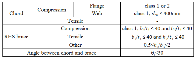
Domeniul de valabilitate pentru care CBFEM este verificat pentru îmbinările T între secțiuni tubulare dreptunghiulare și secțiuni deschise este definit în Tabelul 7.20 din EN 1993-1-8:2005, a se vedea Tab. 7.4.5. În cazul aplicării modelului CBFEM în afara domeniului de valabilitate al FM, trebuie pregătită validarea față de experimente sau verificarea față de un model de cercetare validat pentru a confirma calitatea predicției.
Tab. 7.4.5 Domeniu de valabilitate al îmbinărilor T
Exemplu de referință
Date de intrare
Talpă
• Oțel S235
• IPN280
Element diagonal
• Oțel S235
• RHS 140×80×10
Dimensiunea plasei
• 16 elemente pe cea mai mare inimă a elementului tubular dreptunghiular
Rezultate
• Rezistența de calcul la compresiune/întindere Fc,Rd = 457 kN (Se menționează că rezistența a fost calculată folosind funcția „Stop la deformația limită". În consecință, rezistența CBFEM reală poate fi marginal mai mare.)
• Modul de cedare este plastificarea tălpii
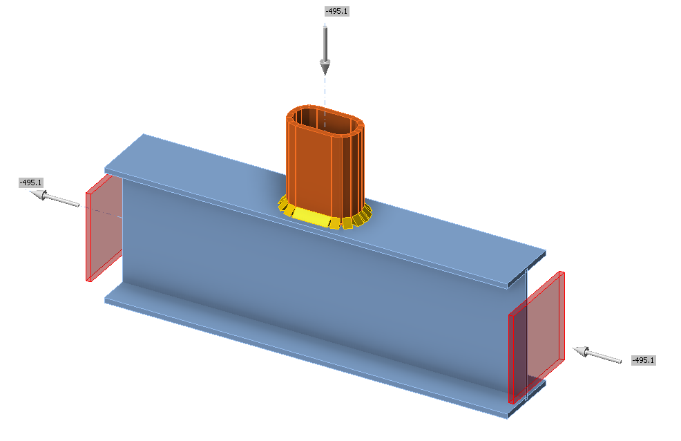
\[ \textsf{\textit{\footnotesize{Fig. 7.4.4 Exemplu de referință pentru talpa IPE270 și elementul diagonal RHS 140×80×10}}}\]