Proiectarea la capacitate a îmbinărilor metalice (AISC)
1 Proiect nou
Lansați IDEA StatiCa (descărcați cea mai nouă versiune) și deschideți fișierul proiectului sursă. Proiectarea nodului este finalizată și pregătită pentru analiza standard Tensiune/Deformație.
2 Calcul și verificare
Porniți analiza tensiune/deformație prin butonul Calculate din panglică. Modelul de analiză este generat automat, calculul este efectuat și puteți vedea rezultatele generale ale verificării în colțul din stânga sus al scenei.
Puteți observa că, pe baza analizei tensiune/deformație, nodul este bine proiectat și trece toate verificările.
Pentru a păstra aceste rezultate, copiați acest element de proiect în colțul din stânga sus, sub Elemente de proiect.
3 Verificarea la capacitate
În noul element de proiect (CON2), modificați următoarele date de intrare pentru a activa verificările limitelor de precalificare conform AISC 358:
- Tip de analiză: Proiectare la capacitate
- Îmbinare precalificată: Activă
- Sistem: Cadru special cu moment încovoietor
- Tip de îmbinare: Secțiune de grindă redusă (RBS)
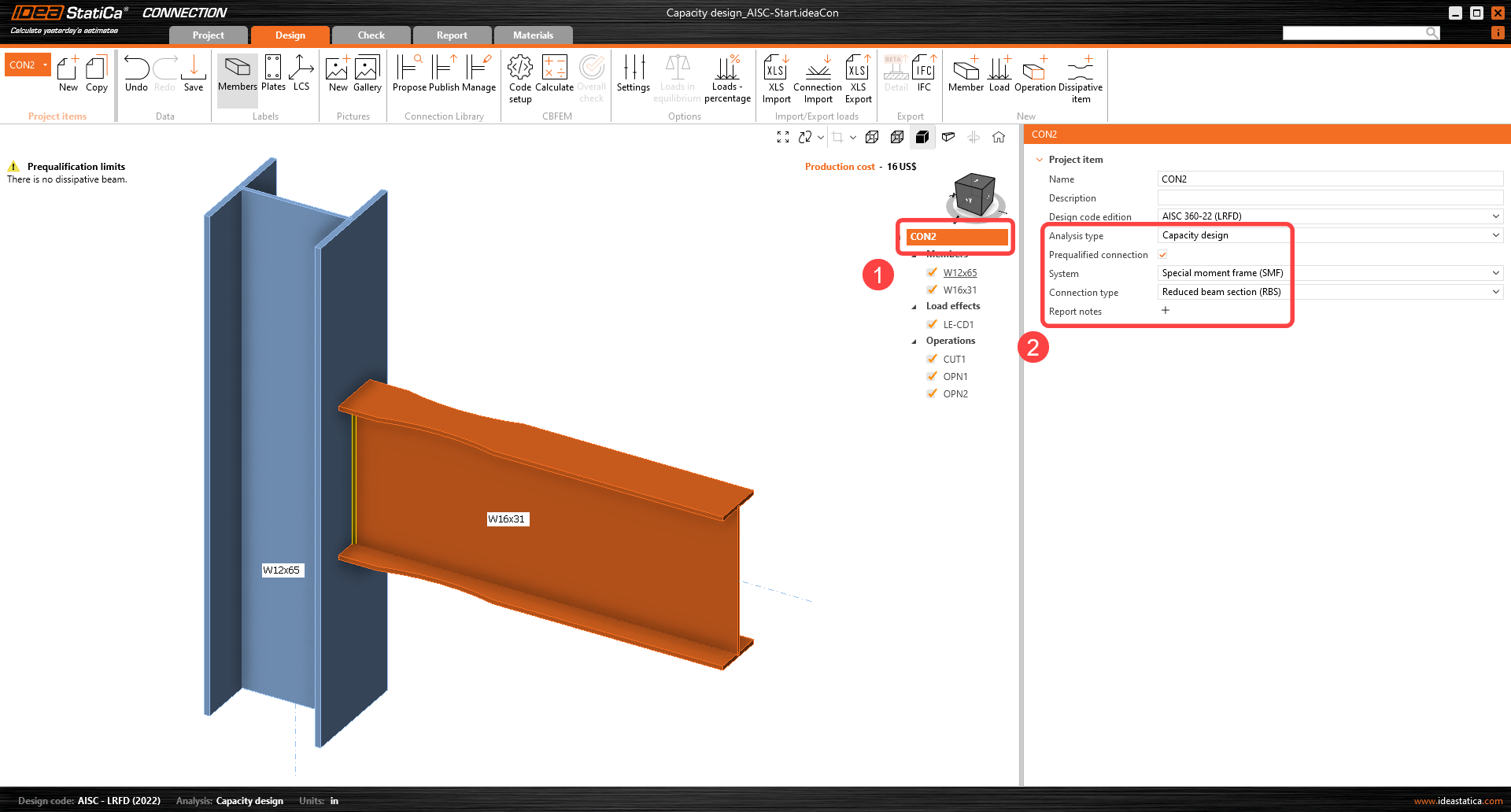
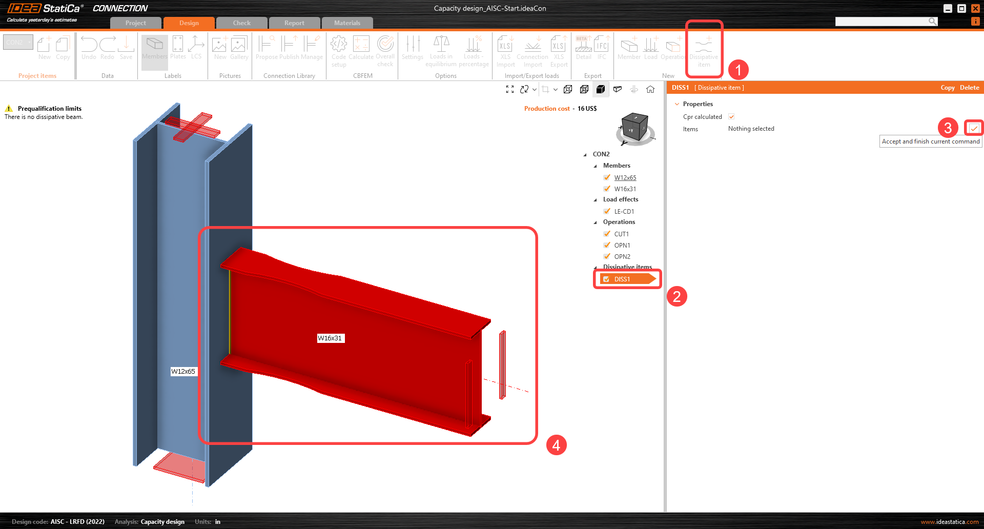
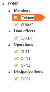
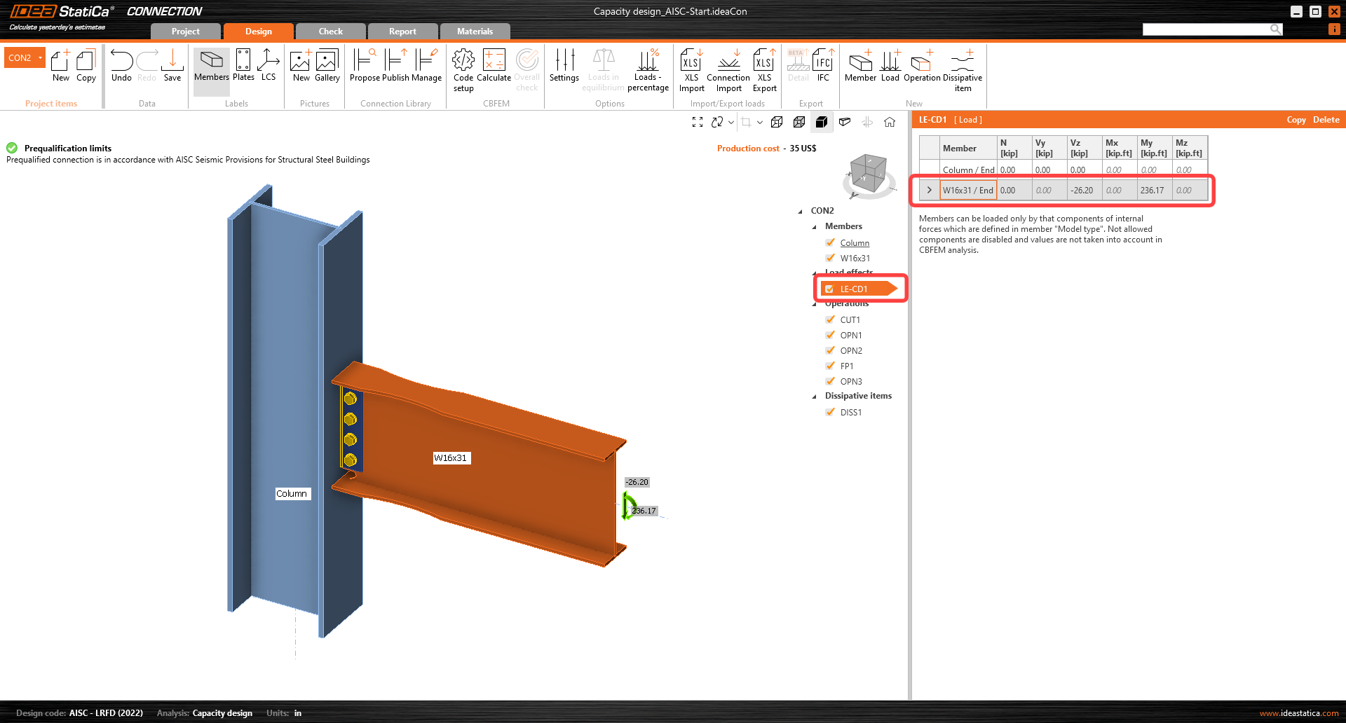
Elementul disipativ trebuie selectat. Un element sau o placă unde se preconizează formarea unei articulații plastice trebuie ales ca element disipativ. Factorul de suprarezistență a materialului și factorul de ecruisare sunt aplicați elementului ales. În acest exemplu, selectați elementul W16x31 ca element disipativ. Acesta poate fi adăugat prin comanda din panglica superioară și confirmați selecția cu bara de spațiu/tasta Enter/clic dreapta.
În proprietățile Elemente, parametrii pentru W16x31 trebuie ajustați: Setați Tipul de model la N-Vz-My, deoarece îmbinarea rezistă momentului încovoietor doar în planul vertical, iar încovoierea în jurul axei minore a grinzii trebuie blocată.
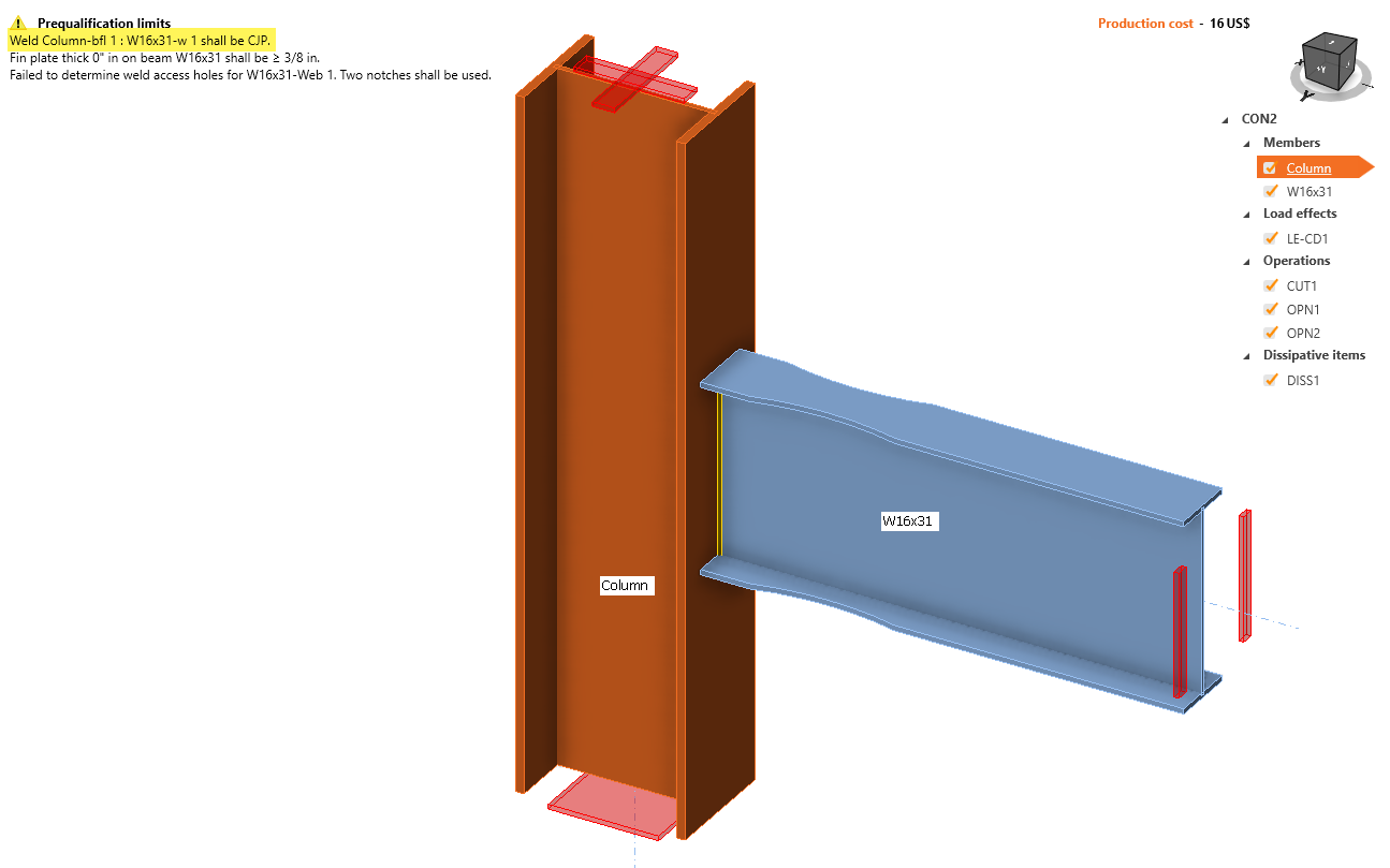
Acum că elementul disipativ este selectat, limitele de precalificare sunt afișate în partea stângă sus a ecranului, în zona modelului:
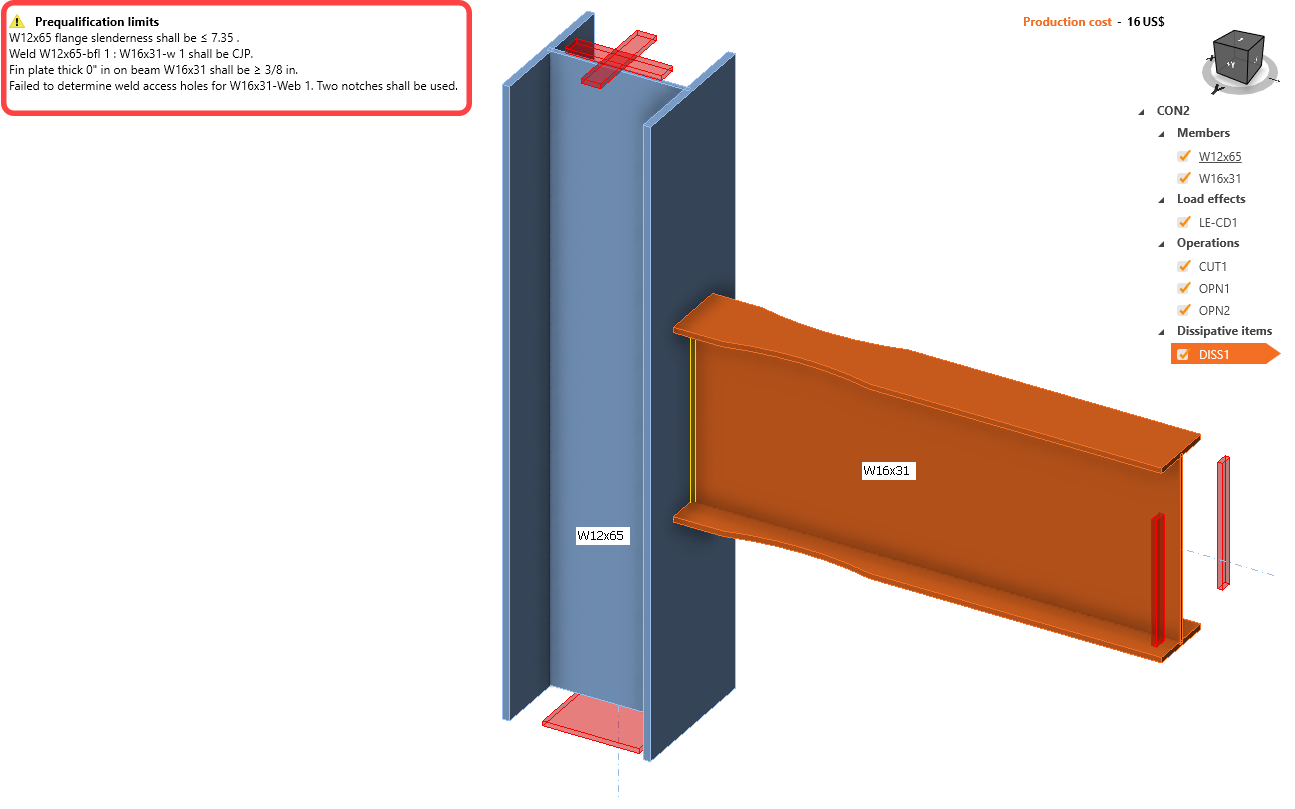
Prima avertizare este legată de AISC 341-16: Capitolul D.1.1b și Tabelul D1.1. Rapoarte limită lățime-grosime. Pentru a remedia prima avertizare, schimbați secțiunea profilului stâlpului la W14X68 făcând clic dreapta pe stâlp și apoi clic pe pictograma plus:
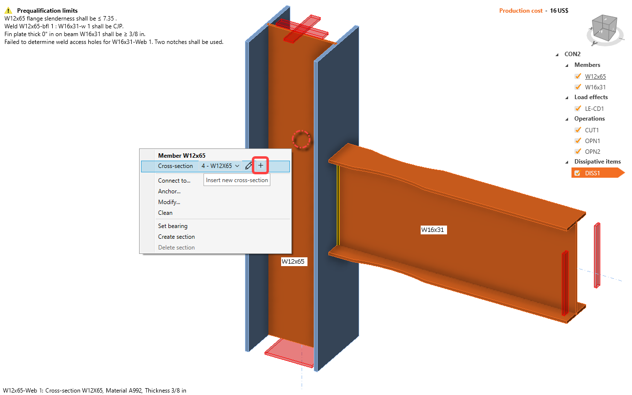
Selectați secțiunea cu tălpi late, derulați în jos până găsiți W (AISC 15.0), utilizați caseta de căutare, faceți clic pe W14X68 și faceți clic pe OK.
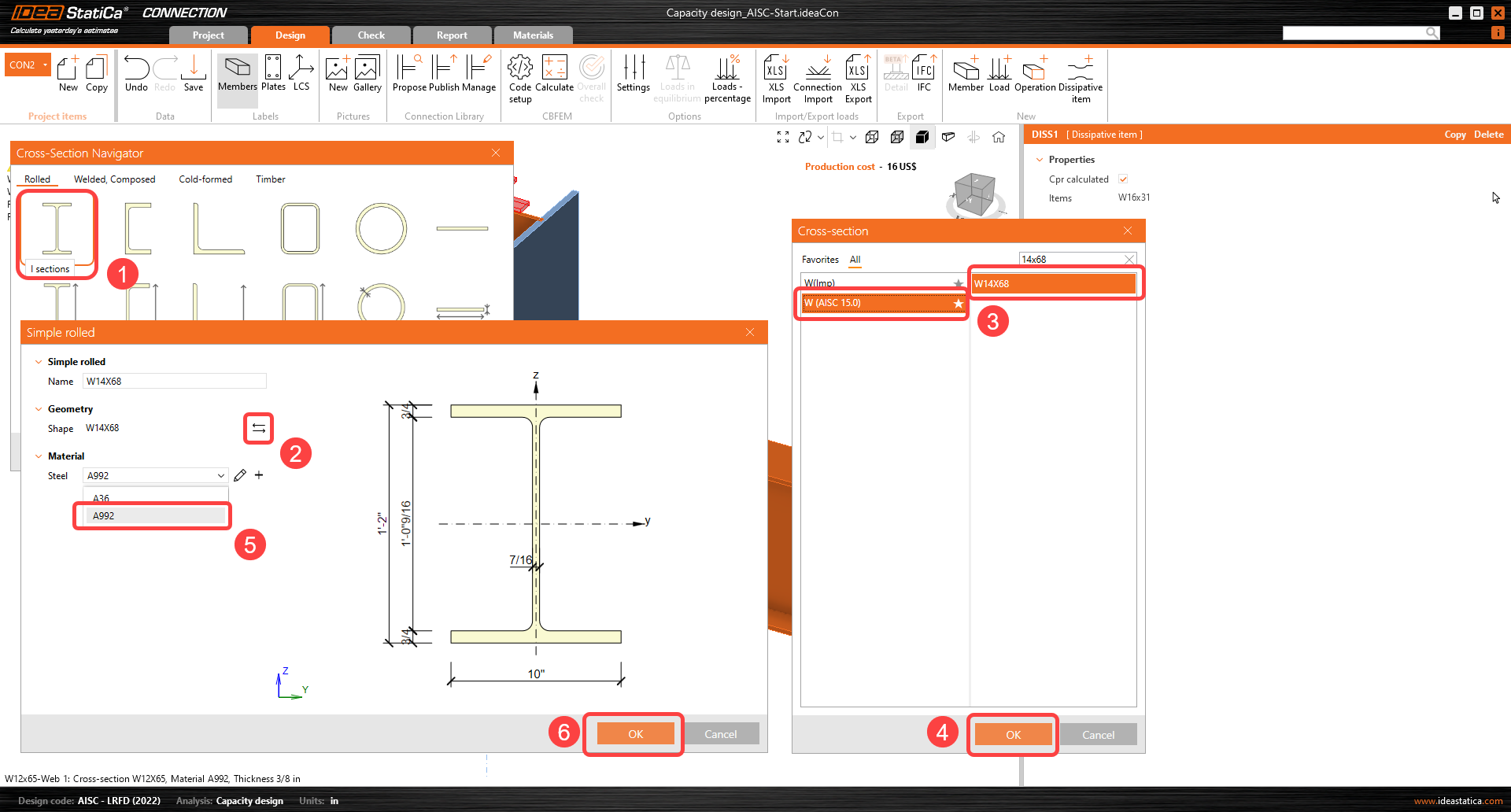
Schimbați numele elementului în Stâlp făcând clic pe numele W12X65 și apăsând tasta F2 sau clic dreapta și selectați Redenumire:
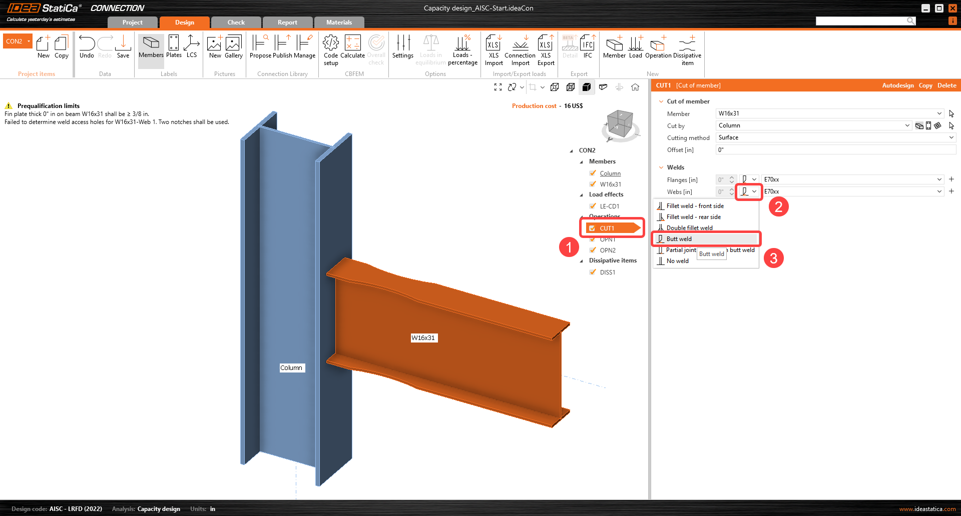
Următoarea avertizare de remediat este legată de sudura inimii grinzii la talpa stâlpului:
Sudura poate fi modificată în operația CUT1; schimbați sudura din sudură de colț dublă în opțiunea sudură cap la cap:
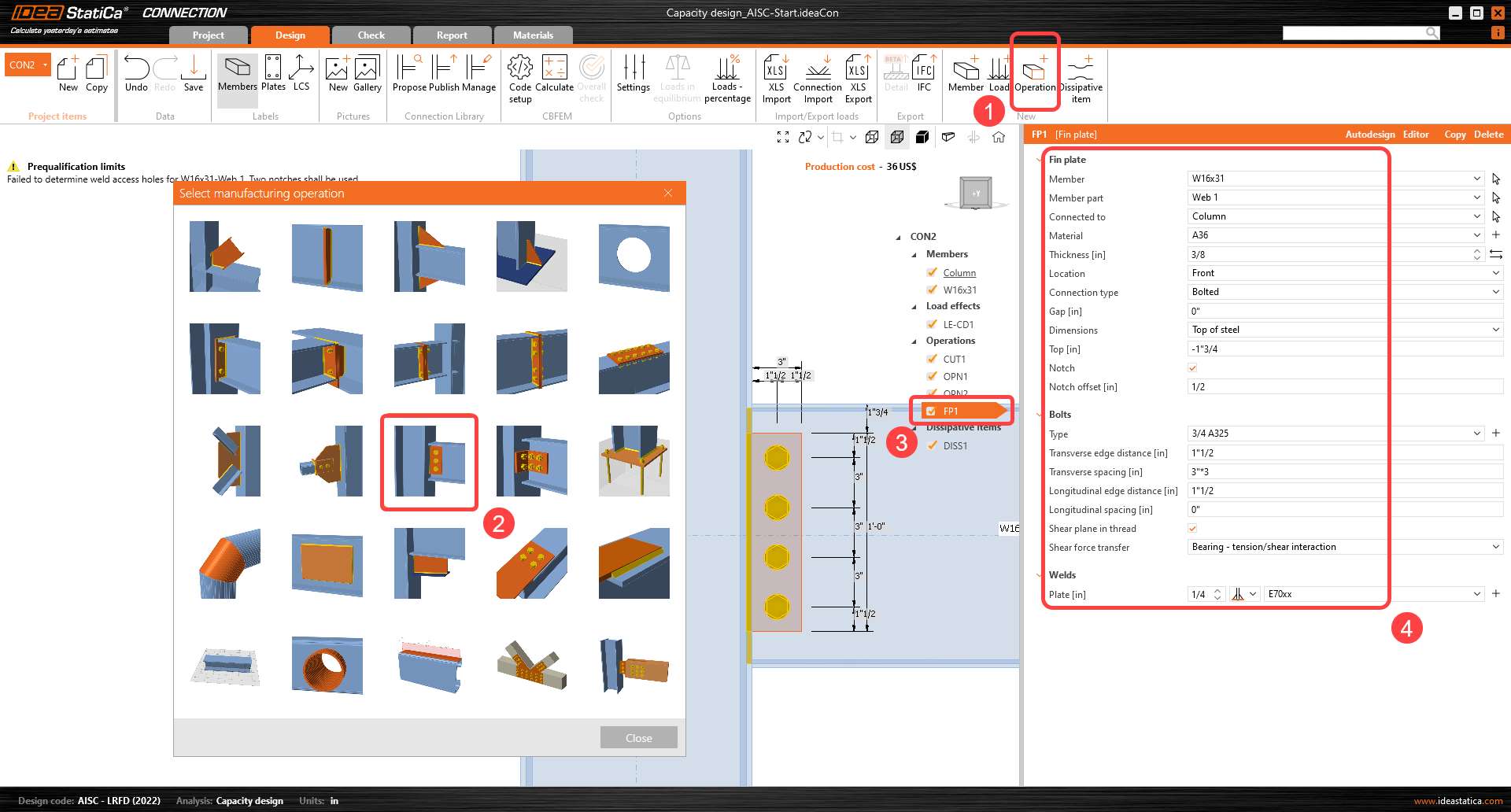
Următoarea avertizare privește cerința pentru placa de forfecare prevăzută în AISC 358 Capitolul 5.6 (2) pentru cadrele speciale cu moment încovoietor.
Faceți clic pe Operație nouă și selectați Operație placă de inimă și introduceți detaliile conform celor prezentate:
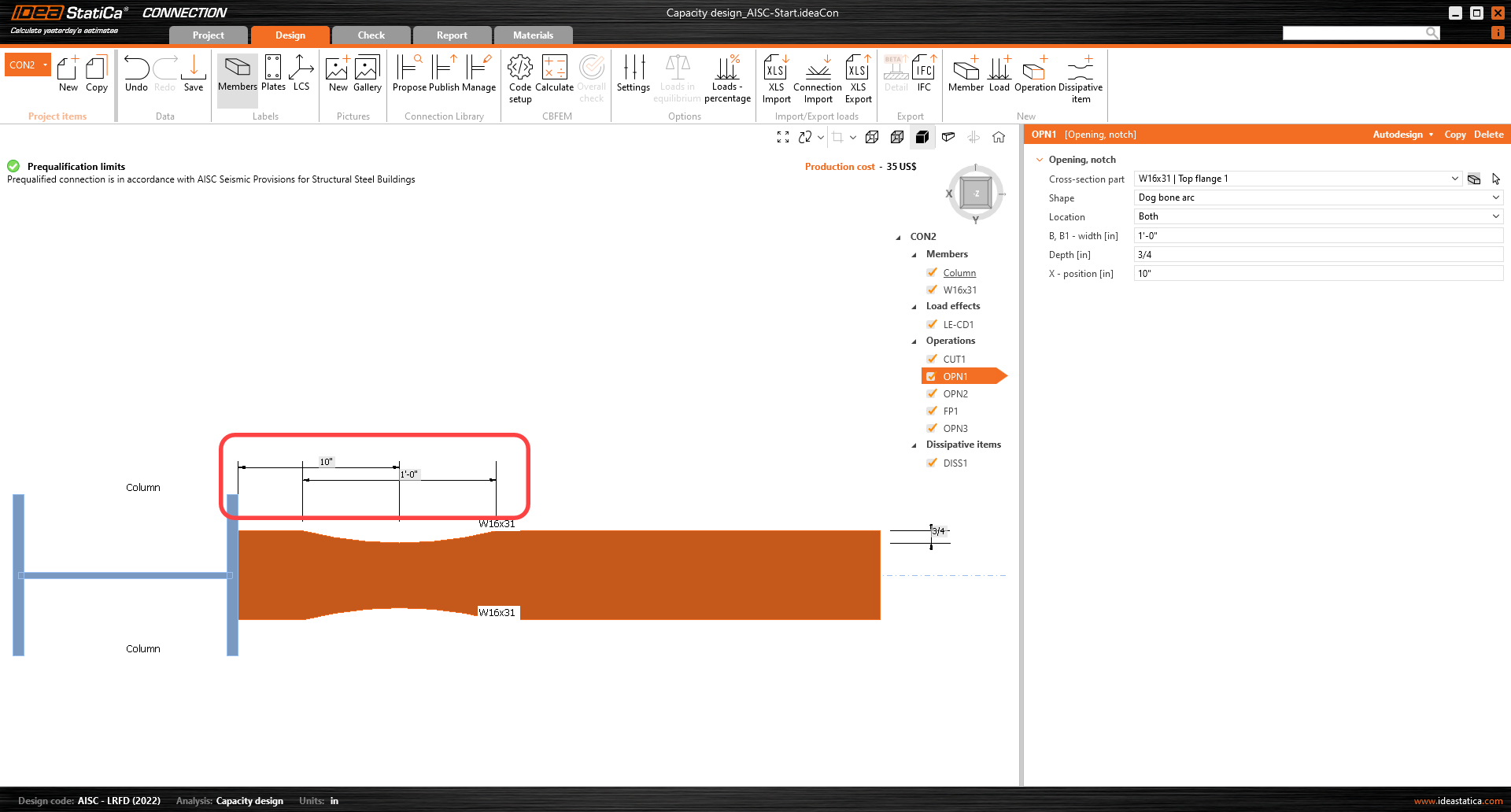
Ultima avertizare se referă la cerința privind găurile de acces la sudură din AISC 358 5.5 (2). Pentru a respecta această verificare de detaliere, adăugați o operație de Deschidere, selectați datele de intrare corespunzătoare și utilizați opțiunea Pre-proiectare pentru decupaje:
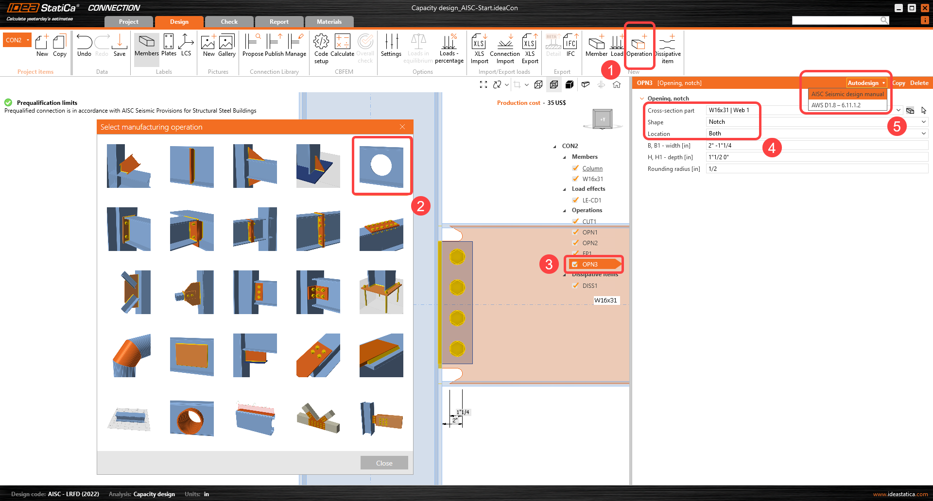
După această operație, îmbinarea îndeplinește limitele de precalificare din standardele AISC 358 și 341.

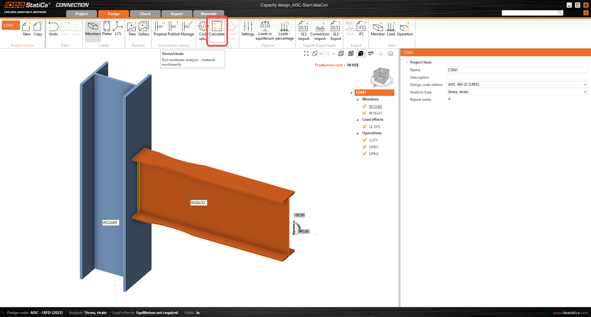
Comutați parametrul Forțe în la Poziție, deoarece astfel poate fi definită poziția exactă a forței aplicate. Poziția articulației plastice este similară cu poziția forței aplicate: X = 17 inch.
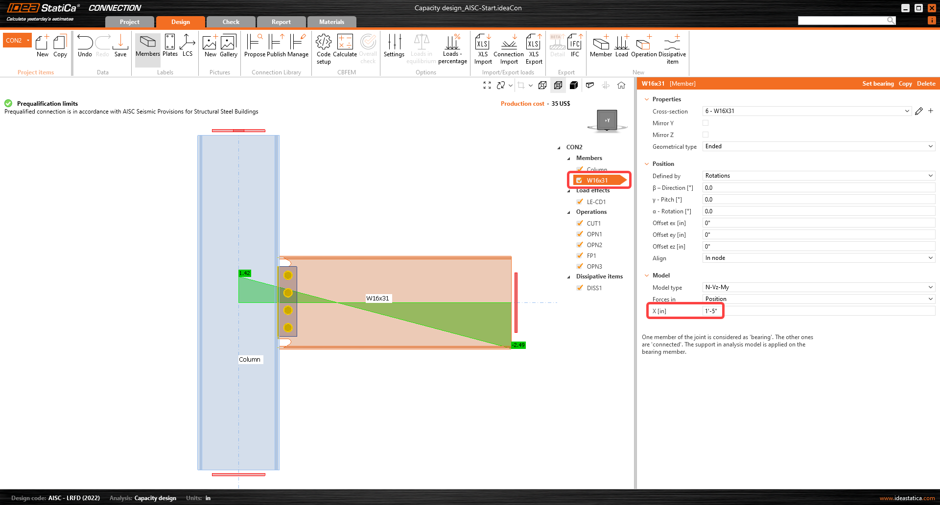
Cum se determină poziția corectă a articulației plastice? Inginerul trebuie să decidă unde va apărea aceasta. De obicei, articulația plastică este determinată în grindă. În acest exemplu, va apărea în mijlocul operației de tip dog bone. Este util să citiți poziția din aplicație (vedere wireframe).
În pasul următor, efectele încărcărilor trebuie definite. Încărcările pentru analiza seismică depind de cod (factorul de suprarezistență a materialului, factorul de ecruisare) și sunt influențate și de rezistența la curgere, caracteristicile geometrice ale secțiunii transversale etc.
Încărcările pentru acest exemplu au fost calculate prin următoarea procedură:
My = Cpr .Ry .Fy .Zpl,y(RBS) și forța tăietoare corespunzătoare Vz = –2 My / Lh, unde:
- Ry – raportul dintre rezistența probabilă și rezistența minimă la curgere – AISC 341-16 – Tabelul A3.1; pentru A992 – Ry = 1,1
- \( C_{pr}=\frac{F_y+F_u}{2\cdot F_y} \le 1.2 \) – factorul de ecruisare; pentru A992 – Cpr = 1,15
- Fy – rezistența caracteristică la curgere; pentru A992 – Fy = 50,0 ksi
- Fu – rezistența caracteristică ultimă; pentru A992 – Fu = 65,0 ksi
- Zpl,y(RBS) – modulul de rezistență plastic; valoarea pentru secțiunea de grindă redusă – Zpl,y,(RBS) = 44,80 in3
- Lh – distanța dintre articulațiile plastice pe grindă; Lh = 250 - (2 . 17) = 216 in
My = 1,15 x 1,1 x 50 x 44,80 = 2834 kip.in = 236,17 kip-ft

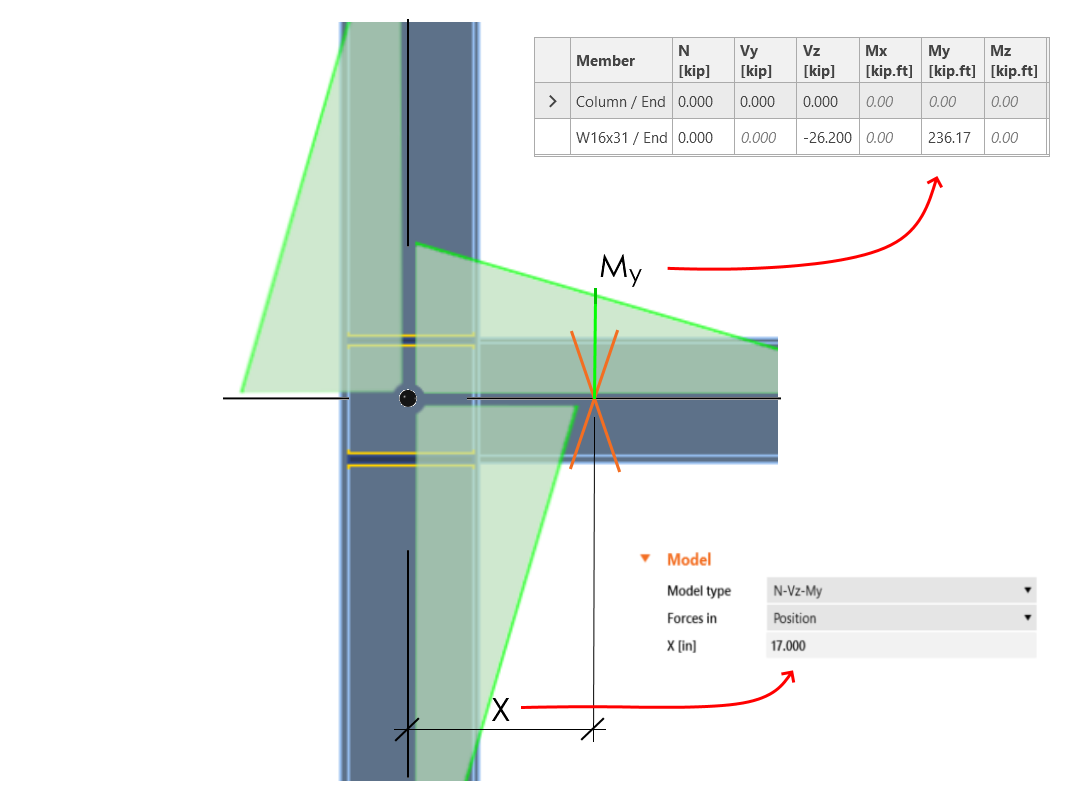
\[ V_{\textrm{Ed}} = \frac{2 \cdot M_{\textrm{y}}}{L_{h}} = 2 \cdot \frac{2834}{216} = 26,2 \, \textrm{kip} \]
Adăugați forța tăietoare și momentul încovoietor calculate ca un nou efect al încărcării (LE).
Forța tăietoare și momentul încovoietor trebuie introduse cu semnele corespunzătoare, astfel încât momentul încovoietor să scadă pe grindă în direcția depărtării de nod.
Acum analiza la capacitate poate fi pornită prin comanda Calculate.
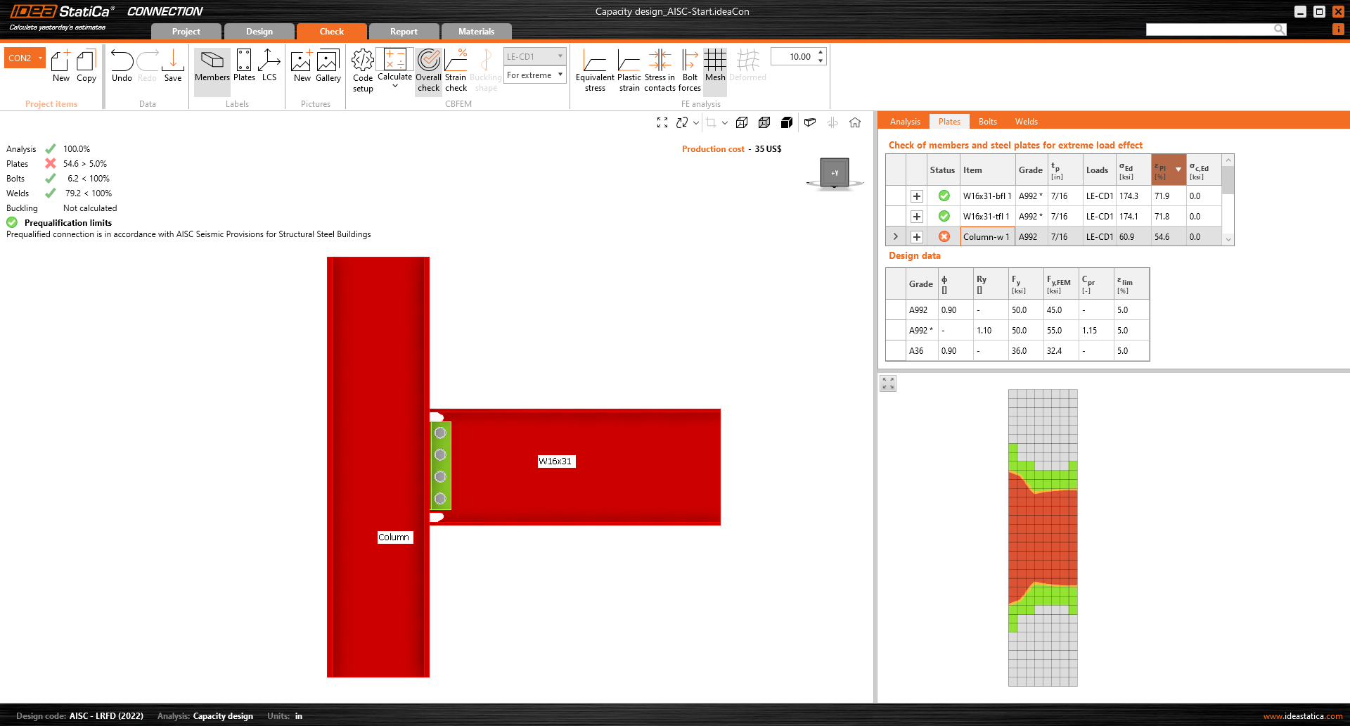
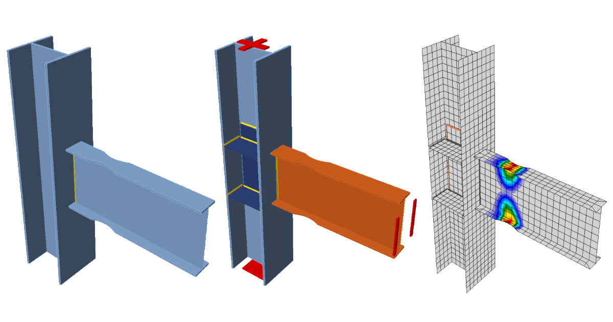
După cum se observă în rezultate și în vederea deformațiilor plastice, stâlpul prezintă o deformație plastică extremă, iar obiectivul principal al proiectării la capacitate împreună cu îmbinările precalificate din procesul de proiectare AISC 358 este de a proiecta un sistem stâlp puternic-grindă slabă. Prin urmare, curgerea și formarea articulației plastice sunt prevăzute să apară în elementul disipativ (grinda selectată), iar în cazul tipului de îmbinare cu secțiune de grindă redusă, intenția este de a avea deformația plastică maximă în partea centrală a secțiunii reduse a grinzii.
Abordarea de proiectare constă în a direcționa cedarea spre grindă. Pașii următori sunt destinați creșterii rezistenței zonei de nod a stâlpului.
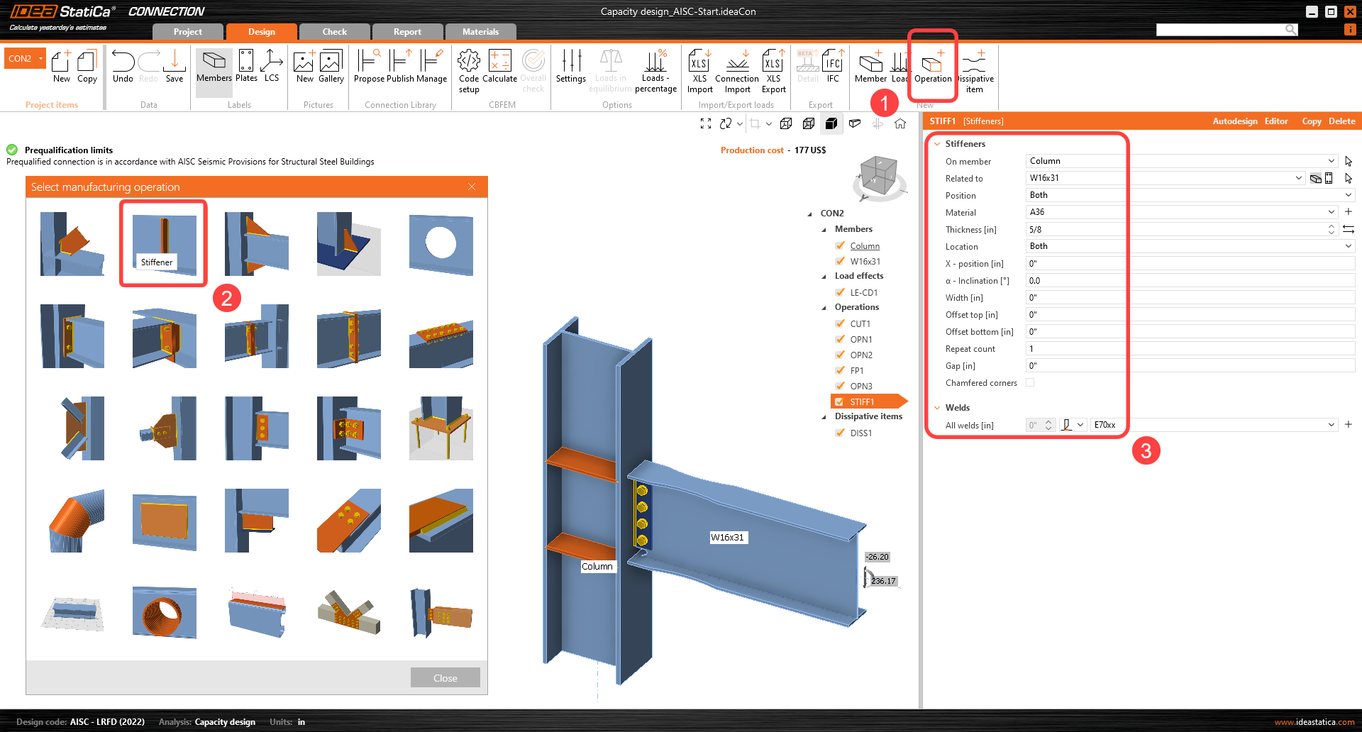
Putem începe prin adăugarea a patru elemente de rigidizare în stâlp, aliniate cu tălpile grinzii. Setați grosimea elementelor de rigidizare la 5/8".
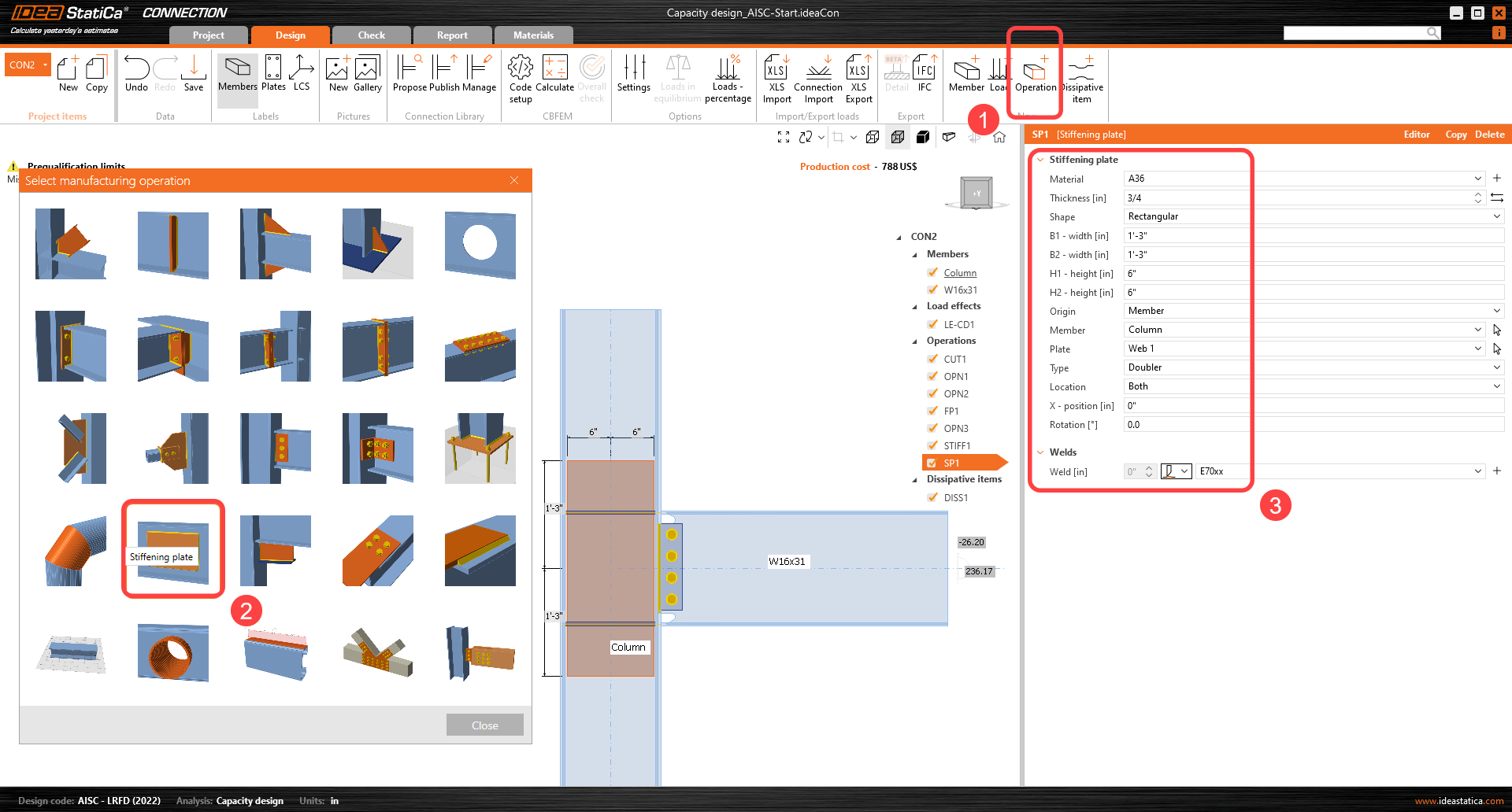
Pentru a crește capacitatea portantă a stâlpului, adăugați o placă de dublare pe ambele fețe ale inimii (adăugați operația de fabricație Placă de rigidizare).
Elementele de rigidizare de la inima stâlpului trebuie tăiate și sudate la plăcile de dublare prin operația de fabricație Tăierea plăcii.
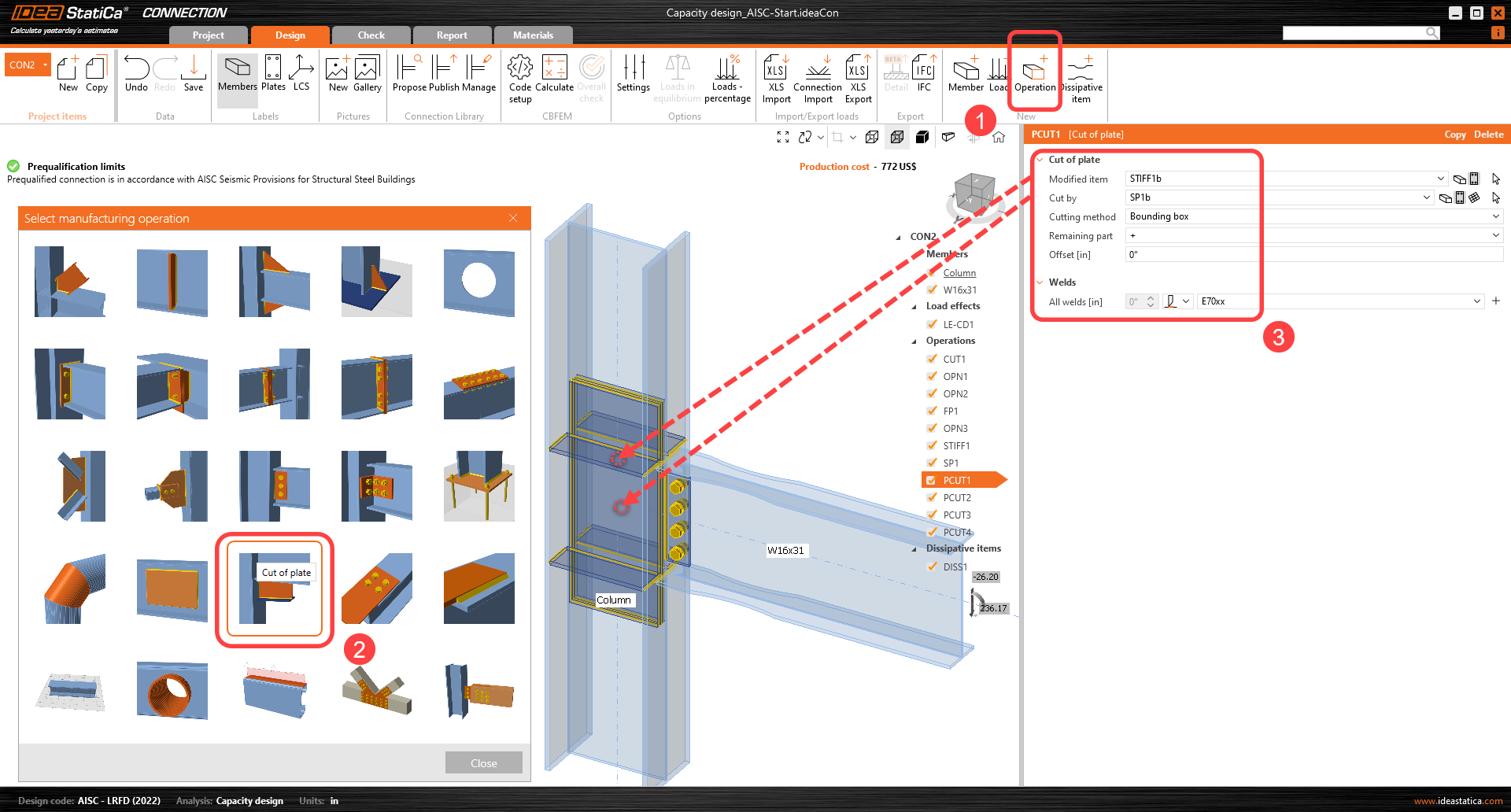
Repetați operația de tăiere a plăcii de patru ori pentru a conecta celelalte elemente de rigidizare față/spate la plăcile de dublare.
*Sfat: Faceți clic dreapta pe prima operație de tăiere, copiați-o după necesitate și treceți cu mouse-ul peste plăci pentru a vedea numele plăcilor de tăiat.
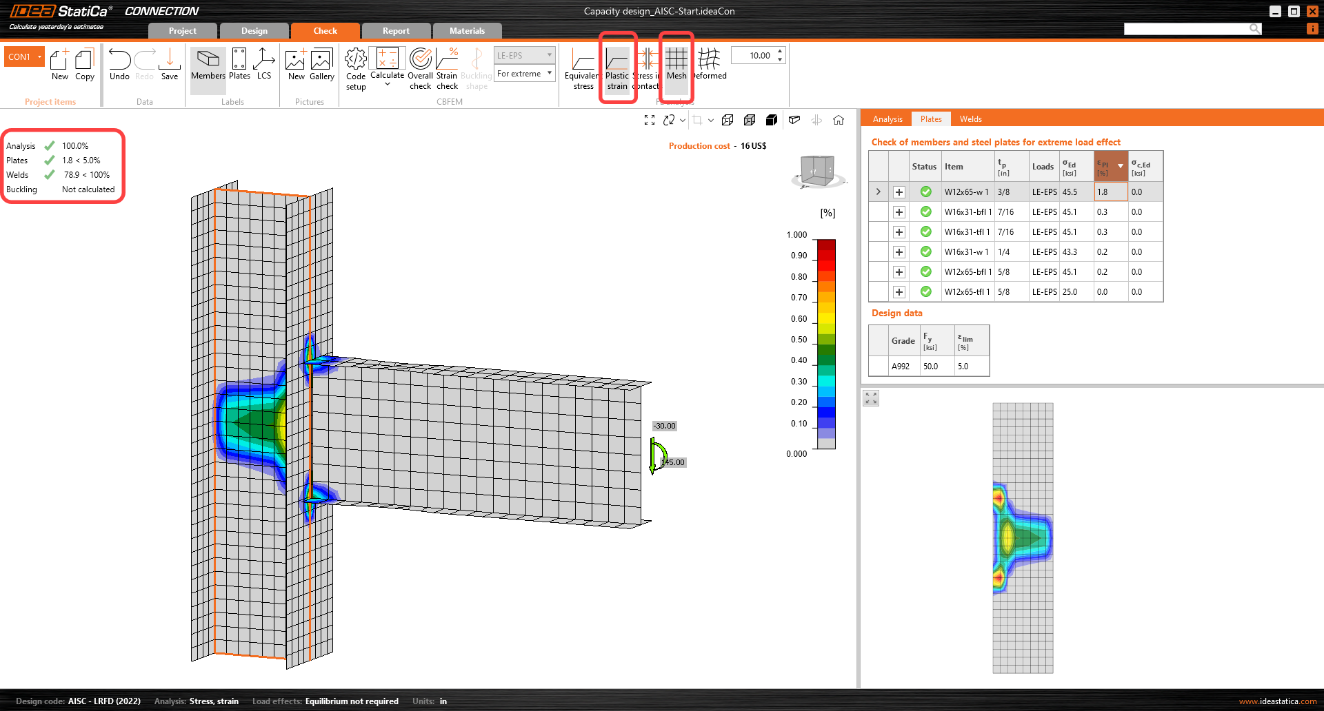
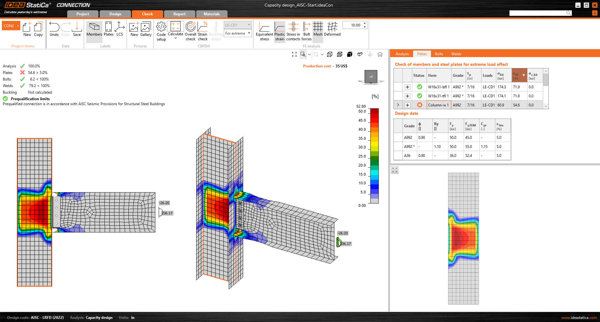
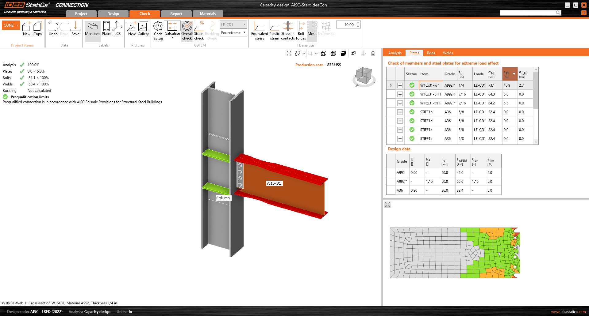
Toate modificările de proiectare sunt acum complete; rulați Calculate în fila Check. Puteți observa că toate componentele (cum ar fi sudurile și șuruburile) au trecut verificarea conform codului. Deformația plastică a plăcilor elementului disipativ nu influențează rezultatele generale.
Apariția articulației plastice poate fi explorată în fereastra de analiză Deformație plastică.
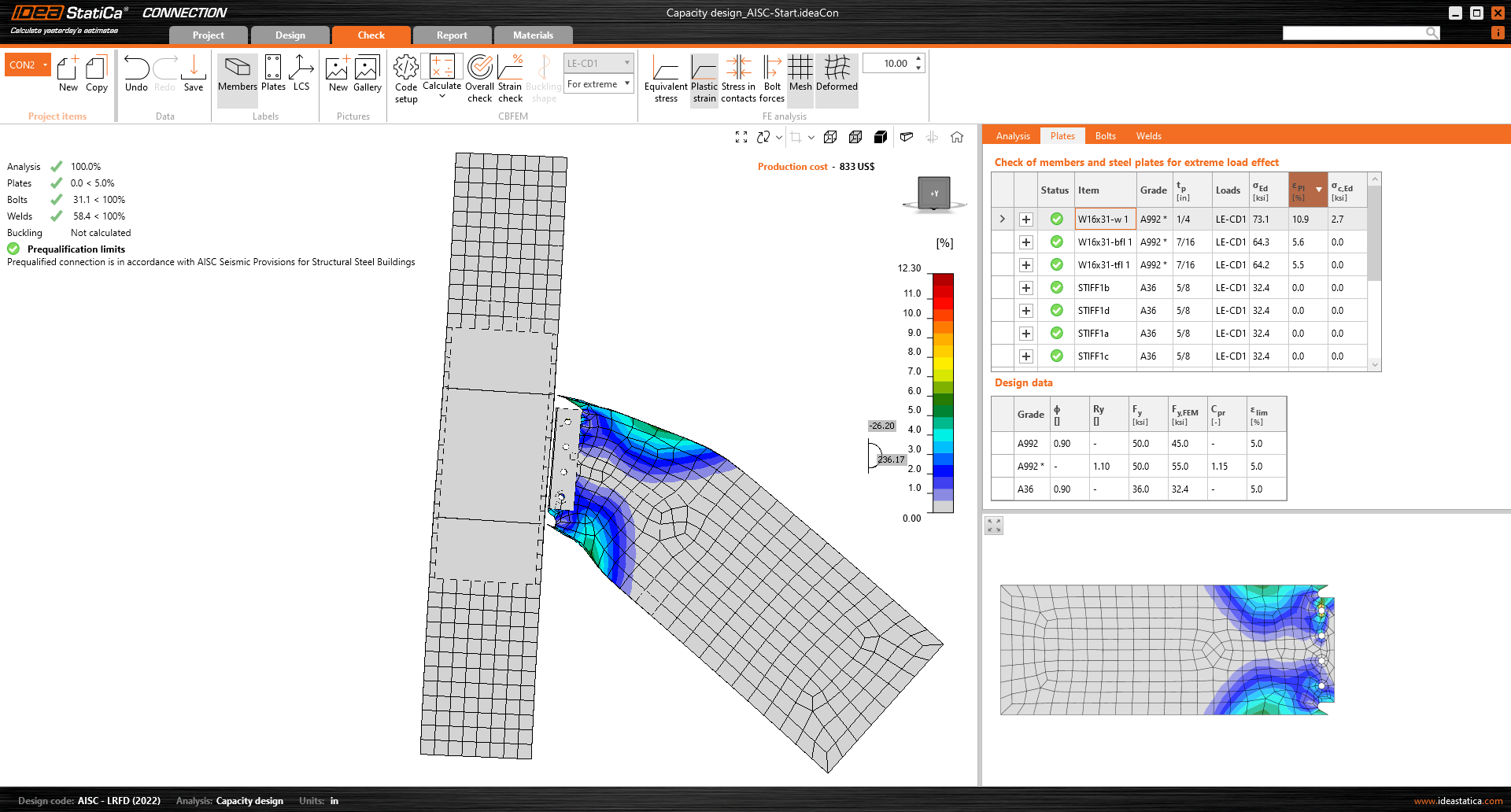
Articulația plastică a apărut la locația prevăzută, iar acest nod a trecut verificările impuse de proiectarea la capacitate.
Pentru o mai bună înțelegere a rezultatelor, consultați Fundamentele teoretice.
4 Raport
În final, puteți revizui Raportul. IDEA StatiCa oferă un raport complet personalizabil pentru tipărire sau salvare într-un format editabil.
La sfârșitul raportului detaliat, există o listă a verificărilor de detaliere a îmbinărilor precalificate cu referința și statusul acestora:
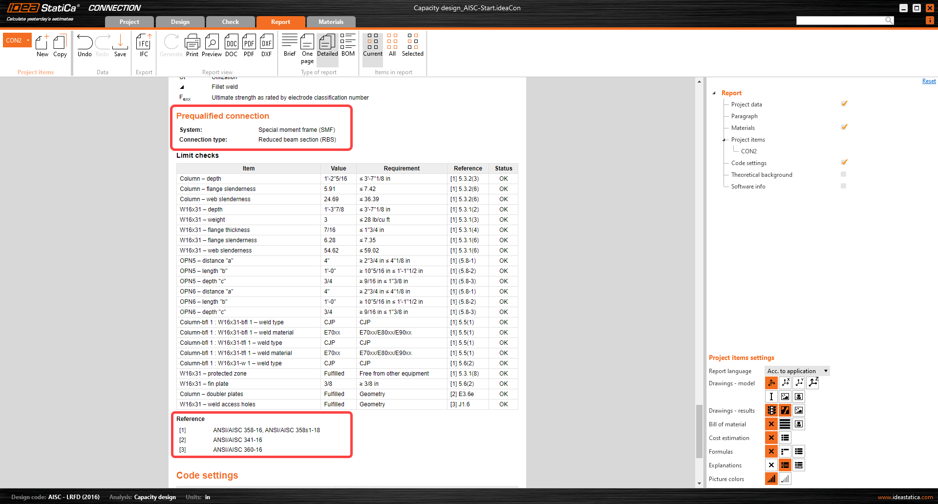
Ați efectuat o verificare a proiectării la capacitate a unei îmbinări structurale precalificate conform AISC 358 și AISC 341.
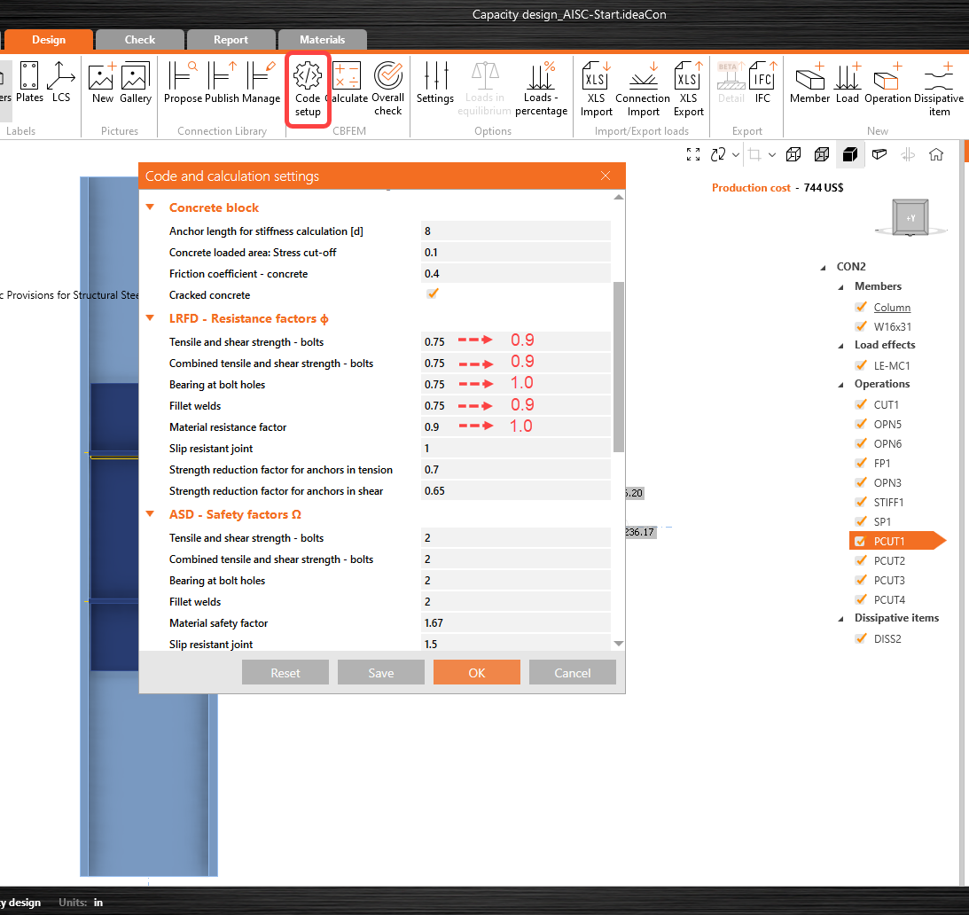
Factori de rezistență
Deoarece cerințele de proiectare pentru îmbinările „precalificate" sunt îndeplinite, iar rezistențele disponibile sunt calculate în conformitate cu AISC 358-16, factorii de rezistență ϕ se iau după cum urmează:
Pentru stările limită ductile ϕd = 1,00
Pentru stările limită neductile ϕn = 0,90
Acești factori pot fi editați în IDEA StatiCa Connection „Configurare cod":